VXJ980902WIRELESS TEMPERATURE PROBE
Integrated Control Corporation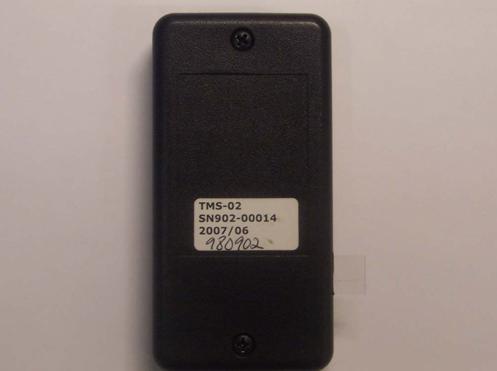
Click to zoom
Application Details
- Equipment Class
- DSC - Part 15 Security/Remote Control Transmitter
- Date of Grant
- Apr 01, 2008
- Application Purpose
- Original Equipment
- Date of Application
- Apr 01, 2008
- Equipment Note
- WIRELESS TEMPERATURE PROBE
- Frequency Range
- 433.92000000 - 433.92000000
- Country
- United States
Documents & Files
Document Text
Text extracted from the exhibit documents filed with the FCC. Open a document above to read the original.
Users Manual
Temperature Minder Site Planning and Installation Manual Temperature Minder Installation Manual – Revision A1 2 Temp Minder™ Site Planning Instructions The Temp Minder™ system is easy to install and only takes about 1 hour. The standard temperature probes are designed to measure temperatures inside refrigerators and freezers. Follow the survey steps below to insure that your wireless Temp Minder will operate reliably for years to come. Survey – A quick survey of the facility allows you to plan where the temperature probes will be located. List all the coolers and freezers that you plan to monitor along with the alarm values. For example: Site plan – Create a sketch of the facility to monitor and mark the placement of the probes. The receiver monitor display is usually located in or around the main office so when an alarm sounds the staff can hear it. Using the Site Sketch and the Probe Survey Chart, measure the farthest probe distance from the receiver and locate one or more repeaters using the rules above. For questions regarding placement of probes and repeaters, please fax the site survey and chart to Integrated Control 631-673-6756 with your company name and contact number or call Temp Minder™ support at 631-673-5100 for assistance. Probe Survey Chart Probe # Probe Name High Alarm, ºF Low Alarm, ºF Time to Alarm On Time Off Time 1 Walk In Refrigerator. 45 33 0:10 12:00 AM 12:00 AM 2 Walk In Freezer 35 -40 0:20 12:00 AM 12:00 AM 3 Salad Bar 45 33 0:10 6:00 AM 10:00 PM 4 Pasta Bar 45 33 0:10 6:00 AM 10:00 PM 5 Ice Cream Freezer 32 -40 0:15 12:00 AM 12:00 AM Temperature Minder Installation Manual – Revision A1 3 Customer Survey Chart Probe # Probe Name High Alarm, ºF Low Alarm, ºF Time to Alarm On Time Off Time 1 2 3 4 5 6 7 8 9 10 11 12 Kitchen Layout Temperature Minder Installation Manual – Revision A1 4 INSTALLATION INSTRUCTIONS 1 – What’s in the box? The standard Temperature Minder box consists of the following parts: 1 – Temp Minder Display 1 – Minder Modem 5 – Temperature Probes 1 – 25’ Cat5 Cable 1 – 8’ Telephone cable 1 – AC-DC Power Supply Prior to starting the install, verify that all parts are in the box 2 – Mounting the Display The Temp Minder display should be mounted in a location that is accessible by the staff and can also be heard if there is a temperature alert - On the back of the display unit, notice two mounting holes. - Using the appropriate drill bit, drill two holes into the wall that the display will be mounted to. - Screw the ICC provided wall screws into the wall. - Mount the display unit accordingly. Temperature Minder Installation Manual – Revision A1 5 3 – Mounting the Minder Modem The minder modem should be mounted within 7’ of the Display unit, within 6’ of an AC power outlet (an extension cord can be used if the outlet is more than 6’ away) and within 25’ of an internet connection. - On the back of the minder modem unit, notice two mounting holes. - Using the appropriate drill bit, drill two holes into the wall that the minder modem will be mounted to. - Screw the ICC provided wall screws into the wall. - Mount the minder modem accordingly. 4 – Running the cables 1. Run the cables using the wiring diagram below. 8’ Telephone Cable To Internet Connection To 25’ Cat5 Cable AC Power AC-DC Outlet Power Supply Temperature Minder Installation Manual – Revision A1 6 5 – Adding the probes If ICC is provided with the Site plan prior to shipping, the temp minder will be shipped with probes already added. Skip to Section 6. Prior to mounting the probes, they should be added to the temp minder first. - Determine where each probe will be placed and label each probe accordingly. - Check the system settings and verify that “Probe Search” is set to Auto. - Pull the tab away from the probe to turn on the probe. - When the tab is pulled away a “New Probe Found” screen will display on the temp minder. - Press “Select” to add that probe. - After adding the probe the temp minder will display the “Limit Settings” Screen. - Edit the limits accordingly. (Refer to operation manual). 6 – Mounting the probes - Find the best location to mount the probe in the area that you will be monitoring. - Drill a hole. - Mount the probe using the ICC provided mounting bracket and screw. - If there is an available screw to use in the location you are monitoring use that screw. Temperature Minder Installation Manual – Revision A1 7 7 – Determining Placement of Repeaters - After mounting the probes go to the signal period screen located in the menu. - Start with the probe closest to the receiver/display. - Notice on the screen the time in seconds counting up to the right of the probe name and temperature. - If the seconds reset to 1 within 40 to 50 seconds no repeater is needed for that location. - If the seconds do not reset to 1, install a repeater near the probe location. - After installing the first repeater view the signal period for the next closest probe and repeat steps. Changes Or Modifications Not Expressly Approved By The Party Responsible For Compliance Could Void The User’s Authority To Operate The Equipment.
Users Manual
Temperature Minder Operation Manual Temperature Minder Operation Manual Rev D1 2 INTRODUCTION Food service requires the monitoring of temperatures of refrigeration systems, heated holding units and food products. Currently these temperatures are being recorded manually by the operator or not at all. The Temp Minder system continuously monitors temperature using wireless probes and transmits the temperature to a receiver-display. A Minder Modem reads the temperature data from the receiver unit and sends the data to an FTP server. Internet Wireless Temp Probes Minder Modem Receiver Display Unit Temp Minder Temperature Minder Operation Manual Rev D1 3 1- THE TEMPERATURE LIST SCREEN When turning on the temp minder system, you will see a boot up screen with the ICC logo. After the boot up screen the Temperature List screen will display. Pressing the list key will display the temperature list screen. This screen displays each probe, the current temperature, and the status of the probe. The probe can display OK, Hi, Lo, or LOS. - OK – indicates that the temperature in the area the Probe is monitoring is within the High and Low ranges that have been defined. - Hi – The temperature in the area the probe is monitoring is above the assigned range. - Lo – The temperature in the area the probe is monitoring is below the assigned range. - LOS – The Temp Minder has missed the signal that the assigned probe is transmitting. If the probe is at Hi, Lo or LOS the probe will be highlighted and blinking on/off indicating that there is an error. Temperature Minder Operation Manual Rev D1 4 2- THE MENU SCREEN NAVIGATING THE MENU SCREEN - To enter the menu screen press the menu key on the temp minder display. - The up/down arrow keys move the cursor from one menu item to the next. - The select key enters the highlighted menu item. - The list key returns you to the Temperature List screen. MENU 1 LAST ALARM Displays the time the last alarm occurred and whether it was a hi/lo temp or a loss of signal. Pressing the up or down arrow key will switch you from probe to probe. If no alarm occurred “No Alarms Logged” will be displayed. Temperature Minder Operation Manual Rev D1 5 MENU 2 SET LIMITS View and edit the settings for each probe: - When entering the Limit Settings screen, - the probe # (P01) will be highlighted. - Press the up/down arrow key to change the probe # that you want to edit. - Press the select key to begin editing. EDIT PROBE NAME - To edit the name of the probe press the select key until the probe name is highlighted. - Press the up/down arrow key to change the highlighted character. - Press the list key to advance to the next character. - Press the menu key to advance to the - previous character. High – The High Temperature is the maximum temperature the location of the probe can be before an alarm on the Temp Minder turns on. To Edit: - Press the select key until the high temperature is highlighted. - Press the up arrow key to increase the temperature. - Press the down arrow key to decrease the temperature. Low – The Low Temperature is the minimum temperature the location of the probe can be before an alarm on the Temp Minder turns on. To Edit: - Press the select key until the low temperature is highlighted. - Press the up arrow key to increase the temperature. - Press the down arrow key to decrease the temperature. On – The “On” setting is the time of day to turn on temperature monitoring. To Edit: - Press the select key until the On hour is highlighted. - Press the up/down arrow key to change the hour. - Press the Select key to advance to minutes. - Press the up/down arrow key to change the minutes. Temperature Minder Operation Manual Rev D1 6 Off – The “Off” setting is the time of day to turn off temperature monitoring. (Temperature will still be monitored but there will be no alarm if the temperature falls out of range). To Edit: - Press the select key until the Off hour is highlighted. - Press the up/down arrow key to change the hour. - Press the Select key to advance to minutes. - Press the up/down arrow key to change the minutes. Delay Alarm – The “Delay Alarm” is the amount of time a probe can be above the temperature of the High setting, or below the temperature of the low setting before an alert alarm turns on. To Edit: - Press the select key until the delay alarm is highlighted. - Press the up/down arrow key to change the time. # missed signals – The “# Missed Signal” is how many missed signals the temp minder can receive before a loss of signal occurs. To Edit: - Press the select key until the # of missed signals is highlighted. - Press the up/down arrow key to change the value. To save changes press the soft left arrow key. MENU 3 – Set Time View and edit the time and date. When entering “Set Time” the hour will be highlighted - Press the up/down arrow key to edit the highlighted value. - Press the select key to advance to the next value. Temperature Minder Operation Manual Rev D1 7 MENU 4 – System Settings Press the up/down arrow key to advance to next setting. Press the select key to edit the highlighted setting. Probe Search – Allows you to turn the search of new probes on, off or auto. (Set to auto when finding new probes). Delete Probe – Allows you to turn the Delete Probe feature on or off Stay on List – Allows you to prevent the All Temps OK screen from automatically displaying Degrees In – Allows the temperature to be displayed in degrees F or degrees C MENU 5 – Signal Period Displays the probe name, the temperature, and the time in seconds, since the last signal was received. MENU 6 – Control Stats Displays the software version and serial number of the Temp Minder, the serial number of the minder modem and the serial number of each probe. Temperature Minder Operation Manual Rev D1 8 3- ADDING AND DELETING PROBE ADDING A PROBE - Check the system settings and ensure that “Probe Search” is set to AUTO. - - When the tab is pulled away a “New Probe Found” screen will display on t…
Text truncated - open the document above for the full version.
External Photos
Retlif Testing Laboratories, Test Report R-12110-1, Integrated Control Corporation FCC ID: VXJ980902 Page 1 of 2 Retlif Testing Laboratories, Test Report R-12110-1, Integrated Control Corporation FCC ID: VXJ980902 Page 2 of 2
ID Label/Location Info
980902 Temperature Probe 17 March 2008 Label Placement 3.5” 1.75” Note: Labels and background are white.
ID Label/Location Info
980902 Temperature Probe 17 March 2008 FCC ID Label FCC ID Label Dimensions: .75” H x 1.25” W Material:Polyester Color: White Text Font: Arial Text Size: FCC ID- 8 point, other text 4.5 point Text Color: Black Adhesive Backed FCC ID: VXJ980902 This device complies with Part 15 of the FCC Rules. Operation is subject to the following two conditions (1) this device may not cause harmful interference, and (2) this device must accept any inter- ference received, including interference that may cause undesired operation.
Internal Photos
Retlif Testing Laboratories, Test Report R-12110-1, Integrated Control Corporation FCC ID: VXJ980902 Page 1 of 2 Retlif Testing Laboratories, Test Report R-12110-1, Integrated Control Corporation FCC ID: VXJ980902 Page 2 of 2
Test Report
Retlif Testing Laboratories, Test Report R-12110-1, Integrated Control Corporation FCC ID: VXJ980902 Page 1 of 21 Technical Information Applicant Manufacturer Name: Integrated Control Corporation Name: Integrated Control Corporation Address: 748 Park Avenue Address: 748 Park Avenue City, State, Zip: Huntington, NY 11743 City, State, Zip: Huntington, NY 11743 Test Specification: FCC Rules and Regulations Part 15, Subpart C, Para. 15.231 Test Procedure: ANSI C63.4:2003 Test Sample Description Test Sample: 433.92 MHz Pulsed Transmitter ( Temperature Probe) Brandname(s): Integrated Control Corporation Part Number: 980902 FCC ID: VXJ980902 Type: Pulsed Transmitter Power Requirements: 3 VDC derived from Panasonic CR2477 Battery Frequency of Operation: 433.92 MHz Applicable Rule Section: Part 15, Subpart C, Section 15.231 Tests Performed Para. 15.231(e), Radiated Emissions, Fundamental and Harmonics Para. 15.231(e), 15.109(a) Radiated Emissions, Spurious Case Para. 15.231(b), Duty Cycle Determination Para. 15.231(c), Occupied Bandwidth Retlif Testing Laboratories, Test Report R-12110-1, Integrated Control Corporation FCC ID: VXJ980902 Page 2 of 21 Test Results 15.231 (a): This device transmits a control signal and is used as an: a remote control transmitter. 15.231 (a) (2) The transmitter is automatically operated. Transmission ends 5 seconds after activation 15.231 (e): The transmitter performs periodic transmissions at predetermined intervals greater than 10 seconds apart and are shorter than 1 second in duration. 15.231 (b): The fundamental field strength did not exceed 4398.7 μV/M (Average) at a test distance of 3 meters. In addition, the requirements of section 15.35 for averaging pulsed emissions and for limiting peak emissions were met. The field strength of harmonic and spurious emissions did not exceed 439.8 μV/M (AVERAGE). 15.231 (c) The Bandwidth of the emission was no wider than 0.25% of the center frequency (54.3 kHz)as measured 20 db down from the modulated carrier. Modifications S/W change that transmits the data at a faster rate, thus reducing the transmit time. Hardware changes to the transmitter PCB: • Added an 18 pf capacitor in series between the XTL and ground. • Added a 10 ohm resistor in series between C6 and C7 (two antenna terminating capacitors). Retlif Testing Laboratories, Test Report R-12110-1, Integrated Control Corporation FCC ID: VXJ980902 Page 3 of 21 Determination of Field Strength Limits The field strength limits shown below are found in Section 15.231: Frequency Limit F1 = 260 1500 = L1 Fo = 433.92 Lo F2 = 470 5000 = L2 The formula below was utilized to determine the limits: Limit = L1 + [(Fo-F1)(L2-L1)/(F2-F1)] Solving Yields Fundamental Limit = 4398.7 μV/m (AVERAGE) @ 3 Meters Harmonic Limit = 439.8 μV/m (AVERAGE) @ 3 Meters Duty Cycle Determination The unit’s RF output was directly coupled to the input of the spectrum analyzer. The analyzer was set for a frequency span of 0 Hz. The sweep time was then adjusted in order to display one full pulse train. The transmitter on time was then summed and compared to the time for one full cycle in order to obtain the duty cycle. (See plots for additional information.) Transmitter On Time = 9.0 milliseconds (maximum per cycle) Transmitter Cycle Time = 100 milliseconds (100 ms maximum) Transmitter Duty Cycle = 9.0 % Calculation 56 x 141 μs (large pulse)= 7.8 milliseconds 16 x 72 μs (small pulse) =1.1 milliseconds 7.8 + 1.1 =9.0 milliseconds Duty Cycle (9ms/100ms) =0.09 Correction Factor =20 log (0.09)=-20.9 dB Retlif Testing Laboratories, Test Report R-12110-1, Integrated Control Corporation FCC ID: VXJ980902 Page 4 of 21 Spectrum Analyzer Desensitization Considerations Due to the nature of the emissions being measured, care was taken to ensure that the resolution bandwidth of the spectrum analyzer was adequate to provide accurate measurements. The following formula was utilized: minimum bandwidth = 1/{minimum pulse width (in seconds) x 1.5} = Hz Setting pulse desensitization equal to zero and utilizing the minimum observed pulse width of 72.0 μs yields a minimum required bandwidth of 9259.3 Hz. FCC specified bandwidths of 100 kHz and 1 MHz were utilized below and above 1 GHz, respectively. General Notes 1. All readings were taken utilizing a peak detector function at a test distance of 3 meters. 2. The duty cycle was applied to the peak readings in order to determine the average value of the emissions. 3. The frequency range was scanned from 30 MHz to 4.34 GHz. All emissions not reported were more than 20 dB below the specified limit. Retlif Testing Laboratories, Test Report R-12110-1, Integrated Control Corporation FCC ID: VXJ980902 Page 6 of 21 Equipment List FCC Part 15.231(b)(1), Duty Cycle Determination EN Type Manufacturer Description Model No. Cal Date Due Date 1086 10X Probe Tektronix 500MHz P6139A 3/7/2007 3/7/2008 887 Oscilloscope Tektronix 200 MHz TDS 2022 12/11/2007 12/11/2008 EQUIPMENT LIST (c), Occupied Bandwidth EN Type Manufacturer Description Model No. Cal Date Due Date 067 Open Area Test Site Retlif 3/10 Meter RNY 9/12/2006 9/12/2009 1086 Oscilloscope Tektronix DC - 500MHz TDS3052B 3/7/2007 3/7/2008 141 Spectrum Analyzer Hewlett Packard 100 Hz - 40 GHz 8566B 4/27/2007 4/27/2008 141B Quasi-Peak Adaptor Hewlett Packard 100 Hz - 1 GHz 85650A 4/27/2007 4/27/2008 512 Graphics Plotter Hewlett Packard N/A 7470A 10/19/2007 10/19/2008 FCC Part 15, Subpart C, Radiated Emissions, Fundamental and Harmonics EN Type Manufacturer Description Model No. Cal Date Due Date 067 Open Area Test Site Retlif 3/10 Meter RNY 9/12/2006 9/12/2009 128 Double Ridged Guide Electro-Mechanics 1 GHz - 18 GHz 3105 3/27/2007 3/27/2008 133 Broadband Pre-Amplifier Electro-Metrics 10 kHz - 1 GHz, 26dB BPA-1000 6/27/2007 6/27/2008 141 Spectrum Analyzer Hewlett Packard 100 Hz - 40 GHz 8566B 4/27/2007 4/27/2008 141B Quasi-Peak Adaptor Hewlett Packard 100 Hz - 1 GHz 85650A 4/27/2007 4/27/2008 206B 6.0 dB Attenuator Texscan 0 - 1.0 GHz FP-50 -…
Text truncated - open the document above for the full version.
Test Setup Photos
Retlif Testing Laboratories, Test Report R-12110-1, Integrated Control Corporation FCC ID: VXJ980902 Page 1 of 4 Duty Cycle Determination, Test Setup Occupied Bandwidth, Test Setup Retlif Testing Laboratories, Test Report R-12110-1, Integrated Control Corporation FCC ID: VXJ980902 Page 2 of 4 Radiated Emissions, Fundamental and Harmonics, X-Axis Setup Radiated Emissions, Fundamental and Harmonics, Y-Axis Setup Retlif Testing Laboratories, Test Report R-12110-1, Integrated Control Corporation FCC ID: VXJ980902 Page 3 of 4 Radiated Emissions, Fundamental and Harmonics, Z-Axis Setup Radiated Emissions, Spurious Case, X-Axis Setup Retlif Testing Laboratories, Test Report R-12110-1, Integrated Control Corporation FCC ID: VXJ980902 Page 4 of 4 Radiated Emissions, Spurious Case, Y-Axis Setup Radiated Emissions, Spurious Case, Z-Axis Setup
Contact Information
Applicant
Dennis A. Gallagher(Manager, New Product Development)
Test Firm
Retlif Testing LaboratoriesScott Wentworth
Technical Specifications
| # | Rule Parts | Frequency Range | Power Output | Emission |
|---|---|---|---|---|
| 1 | 15.231(e) | 433.92 MHz - 433.92 MHz | - | P2D |
Other Applications from Integrated Control Corporation
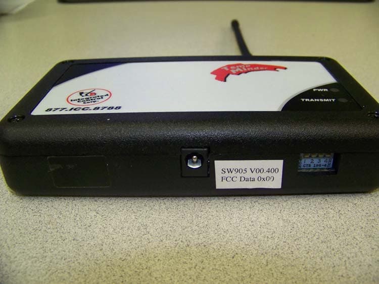
VXJ980905
Apr 07, 2008WIRELESS REPEATER
Equipment Class
DSR - Part 15 Remote Control/Security Device Transceiver