VXTSD30TRACKERCDMA 1X GPSONE Module
Sky Detective, Inc.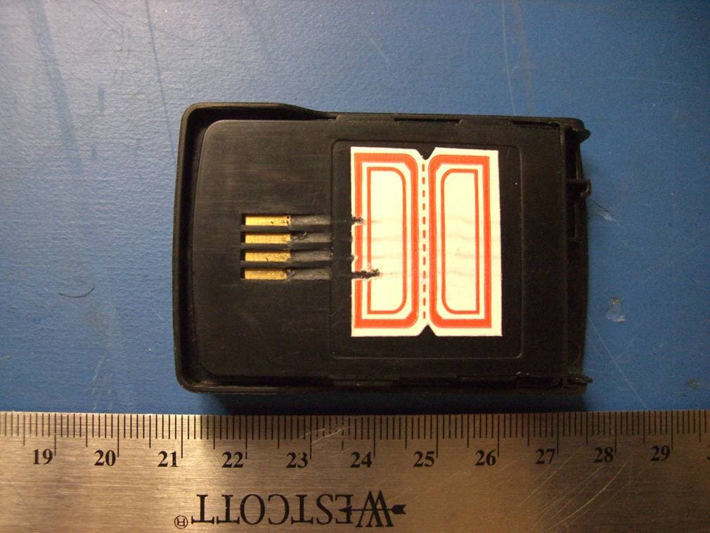
Click to zoom
Application Details
- Equipment Class
- PCB - PCS Licensed Transmitter
- Date of Grant
- Feb 03, 2008
- Application Purpose
- Original Equipment
- Date of Application
- Feb 03, 2008
- Equipment Note
- CDMA 1X GPSONE Module
- Frequency Range
- 1851.25000000 - 1908.75000000
- Company
- Sky Detective, Inc.
- Country
- United States
Documents & Files
Document Text
Text extracted from the exhibit documents filed with the FCC. Open a document above to read the original.
Users Manual
1 SD30 user manual 2 Introduction Sky Detective’s SD30 Tracker uses Qualcomm’s CDMA gpsOne technology. The SD30 provides tracking, security and recovery of high-value packages/assets in real time or on demand. Sky Detective’s SD30 provides accurate location capability, even in impaired environments such as inside trailers and closed packages without the use of external antennas. The device can set to follow up the enwrap, baggage or cars, custody the special crowd. Install the Battery You must install and charge the battery to use your device. Insert the ridge at the side of the battery into the base of the device, then push the battery down and snap it into place. Remove the battery Shove the button as the direction of the arrowhead, slide the battery down as the other arrowhead. 3 SD30 Software Application Features 1 Power key Turn on or off the device,and do some different function according to the pressing time. 2 Accessory Connector Port Insert charger, data cable and other accessories. 3 Indicate light Indicate the currently state. The SD30 has a single programmable button located on the bottom left hand corner of the device. z Turn the SD30 ON or OFF. The SD30 can be programmed to have the button turn the device ON or OFF. The device could accidentally be turned off while being used. This would fundamentally render the device inoperable. Extreme caution should be used. z Check the Status of the Battery. The SD30 can be programmed to have the button provide the status of the battery. A low battery notification could be displayed on the LED or sent over the air. Battery usage would increase and drain the battery at a potentially much faster rate until the battery is fully discharged. This would fundamentally render the device inoperable. Extreme caution should be used. z Request a location fix. The SD30 can be programmed to have the button request a location. A valid location fix request could be displayed on the 4 LED or sent over the air. Battery usage would increase and drain the battery at a potentially much faster rate until the battery is fully discharged. This would fundamentally render the device inoperable. Extreme caution should be used. z Check the Status of CDMA coverage. The SD30 can be programmed to have the button check the status of CDMA coverage. A status of the CDMA coverage could be displayed on the LED. Battery usage would increase and drain the battery at a potentially much faster rate until the battery is fully discharged. This would fundamentally render the device inoperable. Extreme caution should be used. The connector port can use to test GPS net. It has two faction: Test the GPS electric capability connecting the cable; The other, connecting the outside GPS antenna in the poor net can boost up the take over much more GPS signal. Tri-Colour LED The SD30 has a tri-colour LED located on the bottom right hand corner of the device. The Red and Green colours will be very clear. The third colour will be a blend of Red and Green (both lights on). Pressing the power key 1second can tests the currently net, the Green indicate in the CDMA coverage, the Red means out of the service. 5 Pressing 3 seconds can tests the currently battery level, the Green indicate the full charge, the twinkling red light indicates the low charge, the constant red light indicate the extremely low charge. Pressing 5 seconds make once orientation. Pressing 7seconds turns off the device. In the off state, pressing more 0.5 seconds turn on the device, When charging the device, the Red indicates charging the battery, the Green indicates the full battery. SD30 Location Determining Mode MS-Assisted: The SD30 will support MS-Assisted location fixes. In this mode, the device’s location is calculated by the PDE. MS-Based: The SD30 will support MS-Based location fixes. In this mode, the device’s location is calculated by the SD30 using assistance data provided by the PDE. The assistance data is provided by the PDE to the device on request and the assistance data will remain valid for approximately one half hour. Autonomous The SD30 does not support autonomous GPS fixes. SD30 Network Features Control Plane: The SD30 will support control plane. User Plane: The SD30 will support user plane. You can choose to use on control plane or user plane. 6 Human Explosure to RF: 1. This equipment complies with FCC RF radiation exposure limits set forth for an uncontrolled environment. To maintain compliance with FCC RF exposure compliance requirements, please avoid direct contact to the transmitting antenna during transmitting, the minimum distance should be at least 20 cm from the antenna 2. Modification not approved & performed by manufacturer may void the user’s authority to operate the device
Cover Letter(s)
Sky Detective, Inc. Federal Communications Commission Authorization and Evaluation Division Confidentiality Request regarding application for certification of FCC ID: VXTSD30TRACKER Pursuant to Sections 0.457 and 0.459 of the Commission’s Rules, we hereby request confidential treatment of information accompanying this application as outlined below: 1) pcb layout /schematics 2) block diagram 3) user manual 4) BOM part list 5) circuit description The above materials contain trade secrets and proprietary information not customarily released to the public. The public disclosure of these materials may be harmful to the applicant and provide unjustified benefits to its competitors. The applicant understands that pursuant to Section 0.457 of the Rules, disclosure of this application and all accompanying documentation will not be made before the date of the Grant for this application. Sincerely Shichun Tao project manager Date: February 1, 2008
External Photos
Sky Detective, Inc. FCC ID: VXTSD30TRACKER Report No.: R0801107-22 Page 36 of 42 FCC Part 22, 24 Type Approvals Report EXHIBIT C - EUT PHOTOGRAPHS EUT – Front View EUT – Side View 1 Sky Detective, Inc. FCC ID: VXTSD30TRACKER Report No.: R0801107-22 Page 37 of 42 FCC Part 22, 24 Type Approvals Report EUT – Side View 2 EUT – Back View Sky Detective, Inc. FCC ID: VXTSD30TRACKER Report No.: R0801107-22 Page 38 of 42 FCC Part 22, 24 Type Approvals Report EUT with Battery Remove – Front View Battery View
ID Label/Location Info
Sky Detective, Inc. FCC ID: VXTSD30TRACKER Report No.: R0801107-22 Page 34 of 42 FCC Part 22, 24 Type Approvals Report EXHIBIT A - FCC ID LABELING AND WARNING STATEMENT FCC ID Label The FCC labels should contain FCC statement in FCC 2.925 paragraph (a). A sample of the statement is presented hereinafter as reference. Proposed Label Location on EUT The label on these products shall be permanently affixed to the product and shall be readily visible to the purchaser at the time of purchase, as described in Section 2.925(d) of this chapter. "Permanently affixed" means that the label is etched, engraved, stamped, silk-screened, indelibly printed, or otherwise permanently marked on a permanently attached part of the equipment or on a nameplate of metal, plastic, or other material fastened to the equipment by welding, riveting, or a permanent adhesive. The label must be designed to last the expected lifetime of the equipment in the environment in which the equipment may be operated and must not be readily detachable. FCC ID: VXTSD30TRACKER
Internal Photos
Sky Detective, Inc. FCC ID: VXTSD30TRACKER Report No.: R0801107-22 Page 39 of 42 FCC Part 22, 24 Type Approvals Report EUT with Cover off EUT with Shield on – Front View Sky Detective, Inc. FCC ID: VXTSD30TRACKER Report No.: R0801107-22 Page 40 of 42 FCC Part 22, 24 Type Approvals Report EUT with Shield off – Front View EUT with Shield on – Back View Sky Detective, Inc. FCC ID: VXTSD30TRACKER Report No.: R0801107-22 Page 41 of 42 FCC Part 22, 24 Type Approvals Report EUT with Shield off – Back View Power Supply Charger – Front View 1 Sky Detective, Inc. FCC ID: VXTSD30TRACKER Report No.: R0801107-22 Page 42 of 42 FCC Part 22, 24 Type Approvals Report Power Supply Charger – Front View 1 ***** END OF REPORT *****
RF Exposure Info
Sky Detective, Inc. FCC ID: VXTSD30TRACKER Report No.: R0801107-22 Page 10 of 42 FCC Part 22, 24 Type Approvals Report 5 - §1.1307(b) (1) & §2.1091 - RF EXPOSURE 5.1 Applicable Standard According to §1.1310 and §2.1091 RF exposure is calculated. Limits for General Population/Uncontrolled Exposure Frequency Range (MHz) Electric Field Strength (V/m) Magnetic Field Strength (A/m) Power Density (mW/cm 2 ) Averaging Time (minute) Limits for General Population/Uncontrolled Exposure 0.3-1.34 614 1.63 *(100) 30 1.34-30 824/f 2.19/f *(180/f 2 ) 30 30-300 27.5 0.073 0.2 30 300-1500 / / f/1500 30 1500-100,000 / / 1.0 30 f = frequency in MHz * = Plane-wave equivalent power density 5.2 MPE Prediction Predication of MPE limit at a given distance Equation from page 18 of OET Bulletin 65, Edition 97-01 S = PG/4πR² Where: S = power density P = power input to antenna G = power gain of the antenna in the direction of interest relative to an isotropic radiator R = distance to the center of radiation of the antenna Cellular band Maximum peak output power at antenna input terminal: 24.78 (dBm ) Maximum peak output power at antenna input terminal: 300.61 (mW) Prediction distance: 20 (cm) Predication frequency: 836.52(MHz) Antenna Gain (typical): 2.15 (dBi) Antenna gain: 1.64 (numeric) Power density at predication frequency at 20 cm: 0.098 (mW/cm 2 ) MPE limit for uncontrolled exposure at prediction frequency: 0.56 (mW/cm 2 ) Sky Detective, Inc. FCC ID: VXTSD30TRACKER Report No.: R0801107-22 Page 11 of 42 FCC Part 22, 24 Type Approvals Report PCS band Maximum peak output power at antenna input terminal: 21.61 (dBm ) Maximum peak output power at antenna input terminal: 144.88 (mW) Prediction distance: 20 (cm) Predication frequency: 1880 (MHz) Antenna Gain (typical): 2.15 (dBi) Antenna gain: 1.64 (numeric) Power density at predication frequency at 20 cm: 0.047 (mW/cm 2 ) MPE limit for uncontrolled exposure at prediction frequency: 1 (mW/cm 2 ) 5.3 Test Result The EUT is a mobile device. The power density level at 20 cm is 0.098 mW/cm², which is below the uncontrolled exposure limit of 0.550 mW/cm² at 836.4 MHz for Cellular band. The power density level at 20 cm is 0.047 mW/cm², which is below the uncontrolled exposure limit of 1mW/cm² at 1880 MHz for PCS band.
Test Report
Note: This test report is for the customer shown above and their specific product only. It may not be duplicated or used in part without prior written consent from Bay Area Compliance Laboratories Corp. This report must not be used by the customer to claim product certification, approval, or endorsement by NVLAP, NIST, or any agency of the Federal Government FCC PART 22, 24 TYPE APPROVALS EMI MEASUREMENT AND TEST REPORT For Sky Detective, Inc. 2976 E. State Street #120 Eagle, Idaho 83616 ,USA FCC ID: VXTSD30TRACKER This Report Concerns: Original Report Product Type: CDMA 1X GPS ONE Module Test Engineer: James Ma Report No.: R0801107-22 Report Date: 2008-01-29 Reviewed By: Boni Banique Prepared By: Bay Area Compliance Laboratories Corp. 1274 Anvilwood Ave. Sunnyvale, CA 94089, USA Tel: (408) 732-9162 Fax: (408) 732 9164 Sky Detective, Inc. FCC ID: VXTSD30TRACKER Report No.: R0801107-22 Page 2 of 42 FCC Part 22, 24 Type Approvals Report TABLE OF CONTENTS 1 - GENERAL INFORMATION .................................................................................................................................4 1.1 PRODUCT DESCRIPTION FOR EQUIPMENT UNDER TEST (EUT) ...............................................................................4 1.2 MECHANICAL DESCRIPTION...................................................................................................................................4 1.3 EUT PHOTO...........................................................................................................................................................4 1.4 OBJECTIVE.............................................................................................................................................................5 1.5 RELATED SUBMITTAL(S)/GRANT(S) .......................................................................................................................5 1.6 TEST METHODOLOGY.............................................................................................................................................5 1.7 MEASUREMENT UNCERTAINTY..............................................................................................................................5 1.8 TEST FACILITY.......................................................................................................................................................5 2 - SYSTEM TEST CONFIGURATION ....................................................................................................................7 2.1 JUSTIFICATION.......................................................................................................................................................7 2.2 EQUIPMENT MODIFICATIONS.................................................................................................................................7 2.3 POWER SUPPLY AND LINE FILTERS........................................................................................................................7 2.4 LOCAL SUPPORT EQUIPMENT LIST AND DETAILS...................................................................................................7 2.5 INTERFACE PORTS AND CABLING...........................................................................................................................7 3 - SUMMARY OF TEST RESULTS .........................................................................................................................8 4 - §2.1047 - MODULATION CHARACTERISTIC .................................................................................................9 4.1 APPLICABLE STANDARD.........................................................................................................................................9 5 - §1.1307(B) (1) & §2.1091 - RF EXPOSURE ........................................................................................................10 5.1 APPLICABLE STANDARD.......................................................................................................................................10 5.2 MPE PREDICTION.................................................................................................................................................10 5.3 TEST RESULT.......................................................................................................................................................11 6 - §2.1053 - SPURIOUS RADIATED EMISSIONS................................................................................................12 6.1 APPLICABLE STANDARD.......................................................................................................................................12 6.2 TEST PROCEDURE.................................................................................................................................................12 6.3 TEST EQUIPMENT LIST AND DETAILS...................................................................................................................12 6.4 TEST RESULT.......................................................................................................................................................13 7 - §2.1046, §22.913(A), & §24.232(B) – RF OUTPUT POWER.............................................................................14 7.1 APPLICABLE STANDARD.......................................................................................................................................14 7.2 TEST PROCEDURE.................................................................................................................................................14 7.3 TEST EQUIPMENT LIST AND DETAILS...................................................................................................................14 7.4 TEST RESULTS....................................................................................................................................................…
Text truncated - open the document above for the full version.
Test Setup Photos
Sky Detective, Inc. FCC ID: VXTSD30TRACKER Report No.: R0801107-22 Page 35 of 42 FCC Part 22, 24 Type Approvals Report EXHIBIT B - TEST SETUP PHOTOGRAPHS Radiated Emissions - Front View Radiated Emissions - Rear View
Contact Information
Applicant
Jerry Thompson(CEO)
Test Firm
Bay Area Compliance LaboratoryJohn Chan
Technical Specifications
| # | Rule Parts | Frequency Range | Power Output | Emission | Tolerance |
|---|---|---|---|---|---|
| 2 | 24E | 1.85 GHz - 1.91 GHz | 145.00 mW | 1M25F9W | 2.5 ppm |