VY72502007001GUITAR WIRELESS SYSTEM-RECEIVER
ICON INTERNATIONAL DIGITAL LIMITED
Click to zoom
Application Details
- Equipment Class
- CYY - Communications Receiver used w/Pt 15 Transmitter
- Date of Grant
- Jan 30, 2008
- Application Purpose
- Original Equipment
- Date of Application
- Jan 30, 2008
- Equipment Note
- GUITAR WIRELESS SYSTEM-RECEIVER
- Frequency Range
- 902.12500000 - 926.50000000
- Country
- Hong Kong
Documents & Files
Document Text
Text extracted from the exhibit documents filed with the FCC. Open a document above to read the original.
Users Manual
BEETLES series UHFGuitarWirelesssystem BASSWIRELESSSYSTEM ACOUSTICGUITARWIRELESSSYSTEM ELECTRICGUITARWIRELESSSYSTEM ImportantSafetyInstructions 1.Pleasereadallinstructionsbeforeoperatingtheunit. 2.Keeptheseinstructionsforfuturereference. 3.Pleasereadallsafetywarnings. 4.Followmanufacturer'sinstructions. 5.Donotusethisunitnearwaterormoisture. 6.Cleanonlywithadrycloth. 7.Installinaccordancewiththemanufacturer'sinstructions. 8.Donotinstallorusenearanyheatsourcessuchasradiators,heatregisters,stoves,orotherapparatus (includingamplifiers)thatproduceheat. 9.Donotbypassoralterthepolarizedgroundedplug.Seriousdamagemayresultandwillvoidyourwarranty. Apolarizedplughastwobladeswithonewiderthantheother. Agroundingtypeplughastwobladesandathirdgroundingprong. Thewidebladeorthirdprongisprovidedforyoursafety.Iftheprovidedplugdoesnotfitintoyouroutlet, consultanelectrician. 10.ProtectthepowercordfrombeingwalkedonorpinchedChecktheentirewireperiodicallyaswellasallplugs, receptaclesandthepointwherethecordconnectstotheunit. 11.Unplugthisunitduringlightningstormsorwhenunusedforlongperiodsoftime. 12.Referallservicingtoqualifiedpersonnel.Servicingisrequiredwhentheunithasbeendamagedinanyway. User'sManual Introduction WelcomeNote ApersonalwelcometoyoufromthemanagementandemployeesofICON. Guide AllofushereatICONarededicatedtoprovideexcellentproductswithinherentlygoodvalue,andwearedelightedyou havepurchasedoneofourproducts. Wesincerelytrustthisproductwillprovideyearsofsatisfactoryservice,butifanythingisnottoyourcompletesatisfaction, wewillendeavortomakethingsright. WelcometoICON,andthankyouforbecomingpartofourworldwideextendedfamily! Inthesepages,youwillfindadetailedfeaturesdescriptionoftheBeetlesseriesWirelesssystem,aswellasaguidedtour throughitscontrolpanel,step-by-stepinstructionsforitssetup,usage,andfullspecifications. Youwillalsofindawarrantycardenclosed.Pleasefillitoutandmailitinsothatyoucanreceiveonlinetechnicalsupport andupdatewithICONproductsinformationinthefuture. Withpropercare,yourBeetlesWirelessSystemwilloperatetroublefreeformanyyears.Werecommendyourecordyour serialnumberinthespaceprovidedbelowforfuturereference. Pleasewriteyourserialnumberhereforfuturereference: Purchasedat: Dataofpurchase: User'sManual User'sManual Content PackageContents ProductFeatures BeetlesReceiver BeetlesTransmitter QuickSettingupandUsingYourBeetlesSystem ICONFrequencyChart Specifications Services 1 2 3 5 6 9 10 11 PackageContents: Makesurethebelowitemsareprovidedinthepackage: BeetlesWirelessReceiverUnit BeetlesWirelessTransmitterUnit PowerAdapterforReceiver "AngleAdapter"forTransmitterPlug 9VAlkalineBattery 1.5VAlkalineBattery Instructionsmanual User'sManual 1 ProductFeatures PLLsynthesizedtechnology TruediversitytechnologypermitsminimumdropoutsintheRFlink EquippedwithS.A.W.filterforinterference-resistant Built-innoisemuteandsquelchpermitinterference-free UniqueICONEQdesigncircuitfordifferencesinstruments BeetleElectricforElectricGuitar BeetleBassforBass BeetleAcousticforAcousticGuitar TunedantennasforthemoststableRFreception Availablein10differencesChannelswithwideintervaltoensurefree RFinterferencefromeachotherwhenusinginthesamelocation. UniqueDesignandcompactforportable BeetlesReceiver ransmitterBeetlesT RF ON User'sManual2 Pushtoturnonthereceiverpower.(Note:OutputJack(9)mustbeinsertedforthe receivertopowerup) AdjusttheoutputleveloftheReceivertoyourGuitarAmpetc. ThisLEDlightswhenreceivingsignalfromTransmitter. ThisLEDlightswhenoutputsignalfromTransmitterisattheonsetclipping (i.e.Distortionoccurred). ThisLEDlightswhenreceiverbatteryisrunninglow. ThisLEDlightswhenthereceiverisswitchedon. Pushthelatchinthedirectionasindicatedarrowshownbelowandpulltoopenthe latch. 1.PowerSwitch: 2.VolumeSwitch: 3.RFLED: 4.PEAKLED: 5.BATT.LOWLED: 6.ONLED: 7.BatteryCompartmentLatch: Insertstandard9Valkalinebatteryintothecompartment(packageprovided).Please insertthebatteryintherightdirectionasthe+&-polaritymarkingsshown,wrong InsertdirectionwillcauseseveredamagetoyourBeetlesreceiverandwillvoidyour warranty.Also,youmaypoweryourreceiverbytheICONpoweradapterprovided. BeetlesReceiver RF ON 1 2 3 4 5 6 7 Fig1 User'sManual 3 Photo Pulltoliftupthedualantennas.ForoptimumRFreception,pullbothantennasto theirupmostverticalposition. Usethisstandardunbalancedhighimpedance(5-10KOhm)1/4jacktoconnect thereceivertoyouramplifieroraudiomixer.Wiringisasfollows:tiphot,sleeve ground. 8.Antennas: 9.OutputJack: " BeetlesReceiver Fig3 11 10 10.SquelchControl: 11.DCInput: Thiscontroldeterminesthemaximumrangeofthereceiverbeforeaudiosignal dropout.Usually,youshouldleavethisasthefactorydefaultsetting.Also,you mayadjustitbyasmallscrewdriver. ConnecttheprovidedICON'sDCpoweradapterhere. Fig2 9 8 User'sManual 4 1.PowerSwitch: 2.15dBPad: 3.TransmitterPlug: SwitchthepoweroftheBeetlesTransmitterinthedirectionofthearrowshown. Switchtoreducetheoutputofthetransmitterby15dBwhenyourinstrumentis outputtingtoohotasignal. InsertthisstandardplugintoyourGuitaroutputconnector. BeetlesAcousticforElectricAcousticGuitar BeetlesElectricforElectricGuitar BeetlesBassforElectricBass 1/4 DesignedforGibsontypeorallotherinstrumentsthathaveendmount-jacks. (Note:PleaseinsertICON's"AngleAdapter"tosecuretheplugposition) DesignedforFenderStratocastertyperecessedjacks. " Youmayadjusttheangleoftheplugfordifferenttypeofguitarasfollowings: 90degree: 120degree: TM TM BeetlesTransmitter 1 2 4 5 6 4.BatteryCompartment: 5.Antenna: 6.PowerLED: Slidetoopenthelatch.Insertastandard1.5Valkalinebattery(packageprovided) intothecompartment.Pleaseinsertthebatteryintherightdirectionasthe+&- polaritymarkingsshown,wronginsertdirectionwillcauseseveredamagetoyour BeetlesTransmitterandwillvoidyourwarranty. FlexibleantennaforoptimumRFreception. ThisLEDwilllightonceyouturnyourtransmitteron.Itwillstayonwhenthebattery isrunninglow. Fig4 Fig5 User'sManual 5 3
Users Manual
SettingupyourBeetlesWirelesssystemiseasyanditwon'ttakeyoumorethanfewminutestofinish. Followthebelowsteps:- 1.UnpackyourBeetlesWirelessSystem.Youmaysaveallthepackingmaterialsforpackingpurposeinthefuture. 2.CheckifyourBeetlesReceiverarehavingthesameRFChannels(U1-U10,pleaseseeP.9forICONFrequencyChart) labelsasyourBeetlesTransmitter.TheyneededtobesameforyourBeetleswirelesssystemworking. QuickSettingupandUsingYourBeetlesSystem 3.Insertastandard9ValkalinebatteryintotheReceiver'sBatteryCompartmentorpluginthe providedpoweradapterintotheDC9Vjack. 4.PlacetheReceiveronthefloorandliftupitsdualantennastotheverticalposition. 5.MakesurethepowersareoffforyourBeetlesReceiverandTransmitter. 6.PlugthecablejacktotheoutputconnectorofyourReceiverandconnectittoyourAmplifier orMixer(makesurethepowerisoffforyourAmplifierorMixer). 7.TurntheReceiver'sVolumeControlknobtothemostanti-clockwiseposition(i.e.Min.Level) andpushthePowerknobtoturniton.TheONLEDshouldlightred. 8.Insertastandard1.5VbatteryintoyourBeetlesTransmitterBatterycompartment.Then,turn thepoweron.TheONLEDshouldlightonce. 9.ChecktheRFLEDonyourReceiver,itlights(green)indicatingtheReceiverreceivesgood thereforesignalfromyourTransmitter. "" "" "" User'sManual 6 Notice Pleasefollowthebelowproceduretochangetheangleofthejackofyourtransmitter. PresstheknobdownbyyourfingerasshownonDiagram1 Thenrotatethejack,whileyoupressingtheknobdown, toyourdesireangle. YoushouldfeeltheClickPositionwhenthejackturned to90or120. oo "" 7 User'sManual QuickSettingupandUsingYourBeetlesSystem 10.Now,it'stimetosetyouraudiolevels.Turnonyouramplifierormixerandkeepitsleveltominimum. 11.Turntheoutputlevelofyourelectric/acousticguitarorbasstothemaximumandstartplayingatanormalperformance levelandkeepobservingtheBeetlesReceiverRFandPEAKLED.IfPEAKLEDstayonevenReceiver'svolume controlissettoitsminimum,switchonyourBeetlesTransmitter's5dBPadswitch.Otherwise,turnthevolumecontrol anti-clockwiseuntilPEAKLEDoccasionallyblinksredduringtheveryloudestpassages,thenbackitoffjustslightly; thiswillensuremaximumsignaltonoiseratio. 12.Finally,raisethelevelofyourampormixeruntilthedesiredvolumeisreached. 13.IfyouheardistortionorBeetlesReceiverPEAKLEDlightsredevenwiththe15dBPadengagedandreceiverlevel controlissettominimum,pleasereducetheoutputlevelofyourinstrumentuntilthePEAKLEDnolongerstayonall thetime.Conversely,ifyouhearweakandnoisesignalatthedesiredvolumelevel,makesureyourinstrumentissetto maximumoutputlevel;the15dBPadisnotengagedandtheReceivervolumecontrolisturnedup. """" "1" "" """" "" "" QuickSettingupandUsingYourBeetlesSystem 8 User'sManual 902.125MHz 903.500MHz 905.375MHz 907.875MHz 908.500MHz 910.375MHz 912.750MHz 915.500MHz 916.250MHz 918.375MHz 920.125MHz 921.500MHz 922.375MHz 923.500MHz 925.800MHz 926.500MHz U1 U2 U3 U4 U5 U6 U7 U8 U9 U10 U11 U12 U13 U14 U15 U16 IfyourBeetlesWirelessSystemneedstheservicing,followtheseinstructions. U.S.OFFICE: ASIAOFFICE: 1.Ensuretheproblemisnotrelatedtooperationerrororexternalsystemdevices. 2.Keepthisowner'smanual.Don'tsendtheowner'smanualtotheservicecentre. 3.Packtheunitinitsoriginalpackagingincludingendcardandbox.Thisisveryimportant.Ifyouhavelostthepackaging, pleasemakesureyouhavepackedtheunitproperly.ICONisnotresponsibleforanydamagethatoccursduetonon- factorypacking. 4.ShiptotheICONtechnicalsupportcentreorthelocalreturnauthorization. ICONDigitalCorp. 2222PleasantViewRoadSuite#1 Middleton,WI53562USA [email protected] ICON(Asia) SuiteNos.807-810,8/F.,SunleyCentre, No.9WingYinStreet,KwaiChung, NT.,HongKong. [email protected] Foradditionalupdateinformationpleasevisitourwebsiteat: www.icon-global.com Services 11 User'sManual [email protected] www.icon-global.com FCC NOTE: THE MANUFACTURER IS NOT RESPONSIBLE FOR ANY RADIO OR TV INTERFERENCE CAUSED BY UNAUTHORIZED MODIFICATIONS TO THIS EQUIPMENT. SUCH MODIFICATIONS COULD VOID THE USER’S AUTHORITY TO OPERATE THE EQUIPMENT. This device complies with Part 15 of the FCC Rules. Operation is subject to the following two conditions: 1. This device may not cause harmful interference, and 2. This device must accept any interference received, including interference that may cause undesired operation.
Block Diagram
Filer Mixing Frequency Audio Frequency Extend Audio Magnify Output ANT Block diagram of Receiver (crystal frequency 4Mhz)
External Photos
Page 1 o f 1 FCC ID: VY72502007001 Anbotek Compliance Laboratory Limited Report No. 200710664R Figure 1 Receiver of the EUT-Top View Figure 2 Receiver of the EUT-Bottom View
ID Label/Location Info
FCC ID Label Sample for FCC ID: VY72502007001 FCC ID: VY72502007001 This device complies with Part 15 of the FCC Rules. Operation is subject to the following two conditions: 1. This device may not cause harmful interference, and 2. This device must accept any interference received, including interference that may cause undesired operation.
ID Label/Location Info
The proposed Label Location on EUT Proposed FCC ID Label Location
Internal Photos
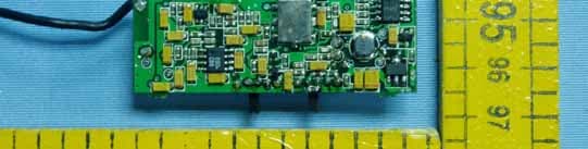
Page 1 o f 1 FCC ID: VY72502007001 Anbotek Compliance Laboratory Limited Report No. 200710664R Figure 1 Receiver of the EUT-Inside View Figure 2 Receiver of the EUT-Inside View
Operational Description
Operational description (Rx) Receiver’s principle: Receive and transmit a high-frequency radio wave into an audio signal to play. A high-frequency radio wave through receiver’s antenna into high-frequency amplifier to selected the working signals. This signal was produce a 10.7MHz signal by a Mixer circuit and the 10.7MHz signal after modulate and amplify into Expansion Circuit. After the Expansion Circuit’s get back, the signal through a 6.35 pin export to play. Power Source is supplied by 9VDC power adaptor.
Operational Description
Operational description (Rx) Receiver’s principle: Receive and transmit a high-frequency radio wave into an audio signal to play. A high-frequency radio wave through receiver’s antenna into high-frequency amplifier to selected the working signals. This signal was produce a 10.7MHz signal by a Mixer circuit and the 10.7MHz signal after modulate and amplify into Expansion Circuit. After the Expansion Circuit’s get back, the signal through a 6.35 pin export to play. Power Source is supplied by 9VDC power adaptor.
Test Report
Page 1 o f 33 FCC ID: VY72502007001 Anbotek Compliance Laboratory Limited Report No. 200710664R FCC TEST REPORT On Behalf of ICON International Digital Limited Guitar Wireless System / Receiver Model No.: Beetle Electric-R, Beetle Bass-R, Beetle Acoustic-R, Air.U-R, Air.U Electric-R, Air.U Bass-R, Air.U Acoustic-R Prepared for : ICON International Digital Limited Address : Unit 808, 8/F., Sunley Centre, 9 Wing Yin Street, Kwai Chung, N.T. Hong Kong Tel: (852) 23982286 Fax: (852) 23982286 Prepared By : Anbotek Compliance Laboratory Limited Address : 2/F, Langfeng Building, Kefa Road North, Hi-tech Industrial Park, Nanshan District, Shenzhen 518057, China Tel: (86) 755-26014771 Fax: (86) 755-26014720 Report Number : 200710664R Date of Test : Dec.03~26, 2007 Date of Report : Dec.27, 2007 TABLE OF CONTENTS Page 2 o f 33 FCC ID: VY72502007001 Anbotek Compliance Laboratory Limited Report No. 200710664R Description Page Test Report Verification 1. GENERAL INFORMATION ............................................................................................................... 4 1.1. Description of Device (EUT) ..........................................................................................................................4 1.2. Description of Test Facility.............................................................................................................................4 1.3. Measurement Uncertainty ...............................................................................................................................5 2. POWER LINE CONDUCTED MEASUREMENT ............................................................................ 6 2.1. Test Equipment ...............................................................................................................................................6 2.2. Block Diagram of Test Setup ..........................................................................................................................6 2.3. Power Line Conducted Emission Measurement Limits (FCC Part 15Class B) ..............................................6 2.4. Configuration of EUT on Measurement..........................................................................................................7 2.5. Operating Condition of EUT...........................................................................................................................7 2.6. Test Procedure.................................................................................................................................................7 2.7. Power Line Conducted Emission Measurement Results.................................................................................7 3. RADIATED EMISSION MEASUREMENT....................................................................................... 8 3.1. Test Equipment ...............................................................................................................................................8 3.2. Block Diagram of Test Setup ..........................................................................................................................8 3.3. Radiated Emission Limit (Class B) .................................................................................................................9 3.4. EUT Configuration on Measurement ..............................................................................................................9 3.5. Operating Condition of EUT...........................................................................................................................9 3.6. Test Procedure...............................................................................................................................................10 3.7. Radiated Emission Measurement Results .....................................................................................................10 4. PHOTOGRAPH ................................................................................................................................... 11 4.1. Photo of Power Line Conducted Emission Measurement .............................................................................11 4.2. Photo of Radiated Emission Measurement ...................................................................................................11 APPENDIX I (Conducted Emission Test Curves) (2 pages) APPENDIX II (Radiated Emission Test Curves) (12 pages) APPENDIX III (Photos of EUT) (5 Pages) TEST REPORT Page 4 o f 33 FCC ID: VY72502007001 Anbotek Compliance Laboratory Limited Report No. 200710664R 1. GENERAL INFORMATION 1.1. Description of Device (EUT) Description : Guitar Wireless System / Receiver Model Number : Beetle Electric-R, Beetle Bass-R, Beetle Acoustic-R, Air.U-R, Air.U Electric-R, Air.U Bass-R, Air.U, Acoustic-R (Note: The above samples are same except the model number & shape of appliances, so we prepare “Beetle Acoustic-R” for test only.) Test Power Supply : DC 9.0V Frequency : 902.125MHz, 903.500MHz, 905.375MHz, 907.875MHz, 908.500MHz, 910.375MHz, 912.750MHz, 915.500MHz, 916.250MHz, 918.375MHz, 920.125MHz, 921.500MHz, 922.375MHz, 923.500MHz, 925.800MHz, 926.500MHz Applicant : ICON International Digital Limited Address : Unit 808, 8/F., Sunley Centre, 9 Wing Yin Street, Kwai Chung, N.T. Hong Kong Manufacturer : Utech Digital corporation Address : No. 1-2, 3 rd Avenue, Dongsheng Industrial Area, Chadong Village, Shiji Town, Panyu District, Guangzhou, Guangdong, China Date of Sample received : Nov.28, 2007 Date of Test : Dec.03~26, 2007 1.2. Description of Test Facility The test facility is recognized, certified, or accredited by the following organizations: Page 5 o f 33 FCC ID: VY72502007001 Anbotek Compliance Laboratory Limited Report No. 200710664R VCCI-Registration No.: R-2197 and C-2383 SGS-CSTC Standards Technical Services Co., Ltd., EMC Laboratory has been registed and fully described in a report filed with the (VCCI)…
Text truncated - open the document above for the full version.
Test Setup Photos
Page 1 o f 1 FCC ID: VY72502007001 Anbotek Compliance Laboratory Limited Report No. 200710664R 4. PHOTOGRAPH 4.1 . Photo of Power Line Conducted Emission Measurement 4.2 . Photo of Radiated Emission Measurement
Contact Information
Applicant
CHRIS WANG(GENERAL MANAGER)
Test Firm
SGS-CSTC Standards Technical Services Co.,Ltd.June Zhang
Technical Specifications
| # | Rule Parts | Frequency Range | Power Output |
|---|---|---|---|
| 1 | 15B | 902.125 MHz - 926.5 MHz | - |
Other Applications from ICON INTERNATIONAL DIGITAL LIMITED
VY72502007002
Jan 29, 2008GUITAR WIRELESS SYSTEM-TRANSMITTER
Equipment Class
DXX - Part 15 Low Power Communication Device Transmitter