VYYDM45EAFSV0Electronic Tubular Motor
NINGBO DOOYA MECHANIC & ELECTRONIC TECHNOLOGY CO., LTD.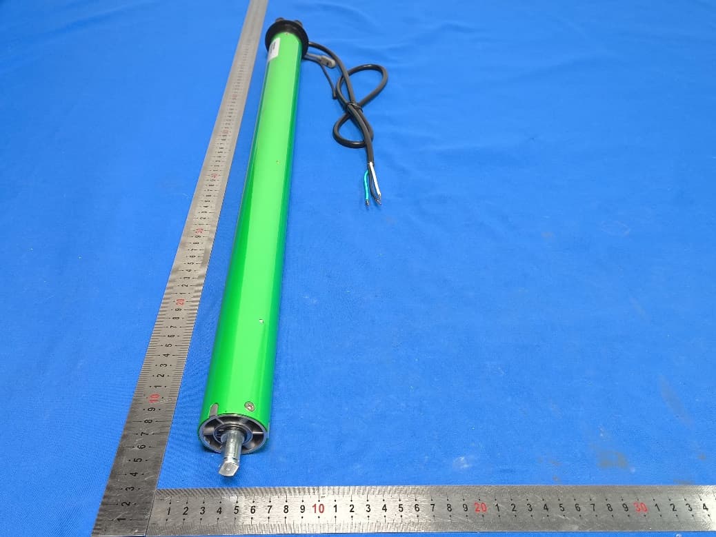
Click to zoom
Application Details
- Equipment Class
- DSC - Part 15 Security/Remote Control Transmitter
- Date of Grant
- Sep 29, 2025
- Application Purpose
- Original Equipment
- Equipment Note
- Electronic Tubular Motor
- Frequency Range
- 433.92000000 - 433.92000000
- Country
- China
Documents & Files
Document Text
Text extracted from the exhibit documents filed with the FCC. Open a document above to read the original.
Users Manual
* For more motor models and specific torque, please refer to the nameplate. DM45EAF/S(120V) InstructionA-03 Button Instructions Attention Never drop, knock, drill or submerge the motor. Keep the power cable in right position as following. Important safety instructions to be read before installation. Incorrect installation can lead to serious injury and will void manufacturer’s liability and warranty. Important Safety Instructions To Be Read Prior To Operation. Essential Settings Step 1 to 3 must be completed to ensure proper operation. DD1602H 15-channel LCD emitter DD1602H Back UP Display STOP DOWN CH+CH- P2 P2 Please read following points of attention carefully before setting. Setting Notice -3- 1. Pls take the wire connnector to protect the extra free wires. 2. Operation ①The valid interval time of the buttons is within 6S, if there is no operation within 6S, the emitter will exit the present setting. ②The motor will jog or beep for hint, please do the next step after the hint. 3. Set limit position: ①After the upper/lower limit setting, and the upper/lower limit position can’t at the same position. ②After limit setting, with power off and memory function. ③Limit delete will clear all limit memory. ④It will exit limit setting when program there is no operation for 2 minutes. 4. If the emitter lost, please setting up again with new emitter. 5. One motor can store maximum 10 channels; after fully stored, if pair new channels, only the last one will be covered circularly. 2 Switch Rotating Direction (Optional) + UP DOWN Press UP and motor runs downwards, try below to switch direction. * The motor needs to be in the reversing operation without limit. * If the code is not aligned, motor jog once and long beep once, jog once for the code; If no limits, this operation will be pairing; if with limits, this operation will be pairing additional emitter. Press and hold UP and DOWN buttons simultaneously for 2S, motor jog once, the direction has been switched successfully. 1 Pairing Power on motor (1 jog and long beep once), within 7S, press STOP for 2S ( 2 jogs and 3 beeps), the motor has been paired successfully. STOP SAFETY NOTE 1. This appliance can be used by children aged from 8 years and above and persons with reduced physical, sensory or mental capabilities or lack of experience and knowledge if they have been given supervision or instruction concerning use of the appliance in a safe way and understand the hazards involved. 2. Children shall not play with the appliance. 3. Cleaning and user maintenance shall not be made by children without supervision. 4. If the supply cord is damaged, it must be replaced by the manufacturer, its service agent or similarly qualified persons in order to avoid a hazard. 5. WARNING: the drive shall be disconnected from its power source during cleaning, maintenance and when replacing parts. 6. The instructions shall state that the A-weighted emis sion sound pressure level of the drive is equal to or less than 70 dB(A), e.g. by writing LpA ≤ 70 dB(A). 7. The mass and the dimension of the driven part shall be compatible with the rated torque and rated operating time. 8. The type of driven part the drive is intended for. 9. WARNING: Important safety instructions. It is important for the safety of persons to follow these instructions. Save these instructions. 10. Do not allow children to play with fixed controls. Keep remote controls away from children. 11. Frequently examine the installation for imbalance and signs of wear or damage to cables and springs. Do not use if repair or adjustment is necessary. 12. Watch the moving shutter and keep people away until the shutter is completely closed. 13. WARNING: Important safety instructions. Follow all instructions, since incorrect installation can lead to severe injury. 14. Before installing the drive, remove any unnecessary cords and disable any equipment not needed for powered operation. Fields of Application Features -1- Specifications Working Temperature: -20°C ~ +65°C Input: AC 120V,60Hz Radio Frequency: 433.92MHz Thermal Protection time: > 4 minutes The motor is suitable for motorization of zip screen. Switch Direction Stall Protection Reset to Factory Mode Signal Repeater Function Electronic Limit Preferred Stop Position Auto Limit Setting Sensitive Stall Detection Built-in Receiver Precise Limit Setting Jog & Tilt Limit Fine Adjustment Motor Mode Switching -2- Wiring Three wires: AC 120V,60Hz 1 2 3 Neutral line = White Live line = Black Earth line = Green Motor Caution 1. Do not expose motor to humid or extreme temperature conditions. 2. Do not drill into motor. 3. Do not cut the antenna and keep it clear from metal objects. 4. Do not allow children to play with this device. 5. If power cable or connector is damaged, do not use. 6. Ensure correct crown and drive adaptor are used. 7. Ensure power cable and aerial are clear and protected from moving parts. 8. Cable routed through walls shall be properly isolated. 9. Motor is to be mounted in horizontal position only. 10. Before installation, remove unnecessary cords and disable equipment not needed for powered operation. 11. Installation and programming to be performed by a qualified professional, use or modification outside the scope of this instruction may void warranty. Motor Installation Drive tube Drive tube Step 1 Cut drive tube to required length. Step 3 Mount correct crown & drive adapter on the motor. Make sure drive adapter fits firmly and crown rotates freely. Step 4 Align the notches on the crown and drive adapter with the drive tube, slide and fit the motor into drive tube. Mount idler and bracket on both ends. Step 2 Ensure tube edge is clean and burr-free. Drive Adapter Crown Circlip Bracket Bracket If there is a limit, the motor is in the upward direction, it will be repelled and protected. After rebounding for a certain distance, it will continue to run upwards. If it encounters resistance at the same position twice, it will stop after the secon…
Text truncated - open the document above for the full version.
Attestation Statements
NINGBODOOYAMECHANIC&ELECTRONICTECHNOLOGYCO.,LTD. No.168ShengguangRoad,Luotuo,Zhenhai,NingboZHEJIANG,China Date:2025-09-22 FederalCommunicationsCommission AuthorizationandEvaluationDivision 7435OaklandMillsRoad Columbia,MD21046 Ref:AttestationStatementsPart2.911(d)(5)(i)Filing FCCID:VYYDM45EAFSV0 ToWhomItMayConcern: NINGBODOOYAMECHANIC&ELECTRONICTECHNOLOGYCO.,LTD.certifiesthattheequipmentfor whichauthorizationissoughtisnot“covered”equipmentprohibitedfromreceivinganequipmentauthorization pursuanttosection2.903oftheFCCrules. NINGBODOOYAMECHANIC&ELECTRONICTECHNOLOGYCO.,LTD.certifiesthattheequipmentfor whichauthorizationissoughtdoesnotincludecybersecurityoranti-virussoftwareproducedorprovidedby KasperskyLab,Inc.oranyofitssuccessorsandassignees,includingequipmentwithintegratedKaspersky Lab,Inc.(oranyofitssuccessorsandassignees)cybersecurityoranti-virussoftwarepursuanttoDA-24-886 andKDB986446D01CoveredEquipmentGuidancesectionB(2a). Deviceisinherentlycompliantbasedonhardwarelimitationsorsoftwarecontrols. or ASoftwareBillofMaterials(SBOM)isprovidedtotheTCBforreview,and Theend-userorthirdpartiescannotinstalladditionalsoftwareonthisdevice. Sincerely, Signatory [xiaofangLiao,MANAGER]
Attestation Statements
NINGBODOOYAMECHANIC&ELECTRONICTECHNOLOGYCO.,LTD. No.168ShengguangRoad,Luotuo,Zhenhai,NingboZHEJIANG,China Date:2025-09-22 FederalCommunicationsCommission AuthorizationandEvaluationDivision 7435OaklandMillsRoad Columbia,MD21046 USA Ref:AttestationStatementsPart2.911(d)(5)(ii)Filing FCCID:VYYDM45EAFSV0 ToWhomItMayConcern: NINGBODOOYAMECHANIC&ELECTRONICTECHNOLOGYCO.,LTD.certifiesthat,asofthedateofthe filingoftheapplication,theapplicantisnotidentifiedontheCoveredList(asaspecificallynamedentityorany ofitssubsidiariesoraffiliates)asanentityproducing“covered”equipment. Sincerely, Signatory [xiaofangLiao,MANAGER]
Attestation Statements
NINGBODOOYAMECHANIC&ELECTRONICTECHNOLOGYCO.,LTD. No.168ShengguangRoad,Luotuo,Zhenhai,NingboZHEJIANG,China Date:2025-09-22 FederalCommunicationsCommission AuthorizationandEvaluationDivision 7435OaklandMillsRoad Columbia,MD21046 USA FCCID:VYYDM45EAFSV0 ApplicantFRN:0017345455 USAgent–AttestationStatement/Part2.911(d)(7) NINGBODOOYAMECHANIC&ELECTRONICTECHNOLOGYCO.,LTD.certifiesthat,asof 2025-09-22,wehavedesignatedFCCUSAgent,LLCtoacceptserviceofprocessonour behalfforFCCID:VYYDM45EAFSV0. NINGBODOOYAMECHANIC&ELECTRONICTECHNOLOGYCO.,LTD.,acceptsto maintainanagentofserviceofprocessintheUnitedStatesfornolessthanoneyearafter eitherthegranteehaspermanentlyterminatedallmarketingandimportationoftheapplicable equipmentwithintheU.S.,ortheconclusionofanyCommission-relatedadministrativeor judicialproceedinginvolvingtheequipment,whicheverislater. FCCUSAgent,LLC,acceptsasofthedateofthefilingofthisapplication,theobligationof beingthedesignatedagentforthepurposeofacceptingserviceofprocessonbehalfof NINGBODOOYAMECHANIC&ELECTRONICTECHNOLOGYCO.,LTD.forFCCID: VYYDM45EAFSV0. DesignatedAgentInformation: CompanyName:FCCUSAgent,LLC U.S.AgentFRN:0033402884 Address:3722IllinoisAvenue,SaintCharles,IL,60174,USA ContactPerson:TimPayne Phone:708-571-3148 Email:[email protected] Sincerely, Company:NINGBODOOYAMECHANIC& ELECTRONICTECHNOLOGYCO.,LTD. DesignatedAgent:FCCUSAgent,LLC CompanyRepresentative:xiaofangLiaoDesignatedAgentRepresentative:TimPayne Signature: Signature:
Cover Letter(s)
NINGBODOOYAMECHANIC&ELECTRONICTECHNOLOGYCO.,LTD. No.168ShengguangRoad,Luotuo,Zhenhai,NingboZHEJIANG,China Date:2025-09-22 FEDERALCOMMUNICATIONSCOMMISSION AUTHORIZATIONANDEVALUATIONDIVISION 7435OAKLANDMILLSROAD COLUMBIA,MD21046 SUBJECT:FCCApplicationforFCCID:VYYDM45EAFSV0 ConfidentialityRequest Towhomitmayconcern, PursuanttotheprovisionsoftheCommission’srulesTitle47Sections§0.457and§0.459,wearerequestingthe Commissiontowithholdthefollowingattachment(s)asconfidentialdocumentsfrompublicdisclosureindefinitely. ☒ BlockDiagram ☐ Tune-UpInformation ☒ OperationalDescription,SBOM ☐ SecurityInformation ☒ Schematics ☐ SoftwareDefinedRadio(SDR)Information ☐ PartsList Theabovematerialscontaintradesecretsandproprietaryinformationnotcustomarilyreleasedtothepublic.The publicdisclosureofthesematerialsmaybeharmfultotheapplicantandprovideunjustifiedbenefitstoits competitors. Inadditionaltoabovementioneddocuments,inordertocomplywiththemarketingregulationsinTitle47CFR §2.803andtheimportationrulesinTitle47CFR§2.1204,whileensuringthatbusinesssensitiveinformation remainsconfidentialuntiltheactualmarketingofnewlyauthorizeddevices,werequestShortTermConfidentiality ofthefollowingattachment(s); ☒ ExternalPhotos ☒ TestSetupPhotos ☒ InternalPhotos ☒ UserManual ☐For45days,pursuanttoPublicNoticeDA04-1705. or ☒For180dayspursuanttoKDB726920D01. TheapplicantunderstandsthatpursuanttoSection0.457oftheRules,disclosureofthisapplicationandall accompanyingdocumentationwillnotbemadebeforethedateoftheGrantforthisapplication. Sincerely, Signatory [xiaofangLiao,MANAGER]
Cover Letter(s)
NINGBODOOYAMECHANIC&ELECTRONICTECHNOLOGYCO.,LTD. No.168ShengguangRoad,Luotuo,Zhenhai,NingboZHEJIANG,China Date:2025-09-22 FEDERALCOMMUNICATIONSCOMMISSION AUTHORIZATIONANDEVALUATIONDIVISION 7435OAKLANDMILLSROAD COLUMBIA,MD21046 SUBJECT:FCCID:VYYDM45EAFSV0 ModelDeclarationLetter DearRegulatoryAuthority, Model(s):DM45EAF/S-10/19,DM45EAF/S-10/32,DM45EAF/S-15/32,DM45EAF/S-20/19,DM45EAF/S-20/32, DM45EAF/S-30/13,DM45EAF/S-40/13,DM45EAH/S-10/19,DM45EAH/S-10/32,DM45EAH/S-15/32, DM45EAH/S-20/19,DM45EAH/S-20/32,DM45EAH/S-30/13,DM45EAH/S-40/13,DM45EAH/S-50/13are sametothemodelDM45EAF/S-50/13,thesemodelsaresamePCBLayout,Schematics,BOM.Onlyfor differentmodelname,brandname,appearancecolor,shellshapeandtheDM45EAF/Sserieshasonemore externalsettingbuttoncomparedtotheDM45EAH/Sseries.(non-metallicanddoesnotaffecttheelectrical structure)fordifferentmarketrequire. Sincerely, Signatory [xiaofangLiao,MANAGER]
Cover Letter(s)
NINGBODOOYAMECHANIC&ELECTRONICTECHNOLOGYCO.,LTD. No.168ShengguangRoad,Luotuo,Zhenhai,NingboZHEJIANG,China Date:2025-09-22 FEDERALCOMMUNICATIONSCOMMISSION AUTHORIZATIONANDEVALUATIONDIVISION 7435OAKLANDMILLSROAD COLUMBIA,MD21046 SUBJECT:FCCApplicationforFCCID:VYYDM45EAFSV0 POWEROFATTORNEY ToWhomItMayConcern: We,theundersigned,herebyauthorizeWaltekTestingGroup(Shenzhen)Co.,Ltd.JandySoonourbehalf,to applytotheFederalCommunicationsCommissiononourequipment.AnyandallactscarriedoutbyWaltek TestingGroup(Shenzhen)Co.,Ltd.JandySoonourbehalfshallhavethesameeffectasactsofourown. ThisistoadvisethatweareinfullcompliancewiththeAnti-DrugAbuseAct.We,NINGBODOOYA MECHANIC&ELECTRONICTECHNOLOGYCO.,LTD.arenotsubjecttoadenialoffederalbenefits pursuanttoSection5301oftheAnti-DrugActof1988,21USC853a,andnopartytotheapplicationissubject toadenialoffederalbenefitspursuanttothatsection. Sincerely, Signatory [xiaofangLiao,MANAGER]
External Photos
Reference No.: WTN25X08217007W Page 3 of 13 Waltek Testing Group (Shenzhen) Co., Ltd. Http://www.waltek.com.cn EXHIBIT 2 - EUT EXTERNAL PHOTOGRAPHS EUT View 1 EUT View 2 Reference No.: WTN25X08217007W Page 4 of 13 Waltek Testing Group (Shenzhen) Co., Ltd. Http://www.waltek.com.cn EUT View 3 EUT View 4 Reference No.: WTN25X08217007W Page 5 of 13 Waltek Testing Group (Shenzhen) Co., Ltd. Http://www.waltek.com.cn EUT View 5 EUT View 6 Reference No.: WTN25X08217007W Page 6 of 13 Waltek Testing Group (Shenzhen) Co., Ltd. Http://www.waltek.com.cn EUT View 7 EUT View 8
ID Label/Location Info
Reference No.: WTN25X08217007W Page 1 of 13 Waltek Testing Group (Shenzhen) Co., Ltd. Http://www.waltek.com.cn ANNEX EXHIBIT 1 - PRODUCT LABELING Proposed FCC ID Label Format Specifications: The label shall be securely affixed to a permanently attached part of the device, in a location where it is visible or easily accessible to the user, and shall not be readily detachable. The label shall be sufficiently durable to remain fully legible and intact on the device in all normal conditions of use throughout the device’s expected lifetime. Reference No.: WTN25X08217007W Page 2 of 13 Waltek Testing Group (Shenzhen) Co., Ltd. Http://www.waltek.com.cn Proposed Label Location on EUT FCC ID Label Location
Internal Photos
Reference No.: WTN25X08217007W Page 7 of 13 Waltek Testing Group (Shenzhen) Co., Ltd. Http://www.waltek.com.cn EXHIBIT 3 - EUT INTERNAL PHOTOGRAPHS EUT Housing and Board View 1 Solder Board-Component View 1 Reference No.: WTN25X08217007W Page 8 of 13 Waltek Testing Group (Shenzhen) Co., Ltd. Http://www.waltek.com.cn Solder Board-Component View 2 Solder Board-Component View 3 Reference No.: WTN25X08217007W Page 9 of 13 Waltek Testing Group (Shenzhen) Co., Ltd. Http://www.waltek.com.cn Solder Board-Component View 4 Solder Board-Component View 5 Reference No.: WTN25X08217007W Page 10 of 13 Waltek Testing Group (Shenzhen) Co., Ltd. Http://www.waltek.com.cn Antenna View Antenna
RF Exposure Info
1. RF Exposure Requirements 1.1 General Information Client Information Applicant: NINGBO DOOYA MECHANIC & ELECTRONIC TECHNOLOGY CO., LTD. Address of applicant: No.168 Shengguang Road, Luotuo, Zhenhai, Ningbo ZHEJIANG, China Manufacturer: NINGBO DOOYA MECHANIC & ELECTRONIC TECHNOLOGY CO., LTD. Address of manufacturer: No.168 Shengguang Road, Luotuo, Zhenhai, Ningbo ZHEJIANG, China General Description of EUT: Product Name: Electronic Tubular Motor Trade Name: / Model No.: DM45EAF/S-50/13 Adding Model(s): DM45EAF/S-10/19, DM45EAF/S-10/32, DM45EAF/S-15/32, DM45EAF/S-20/19, DM45EAF/S-20/32, DM45EAF/S-30/13, DM45EAF/S-40/13, DM45EAH/S-10/19, DM45EAH/S-10/32, DM45EAH/S-15/32, DM45EAH/S-20/19, DM45EAH/S-20/32, DM45EAH/S-30/13, DM45EAH/S-40/13, DM45EAH/S-50/13 Rated Voltage: AC 120V Power Adaptor : / FCC ID: VYYDM45EAFSV0 Equipment Type: Portable device Technical Characteristics of EUT: Frequency Range: 433.92MHz Max. Field Strength: 433.92MHz: 81.68dBuV/m(3m) Data Rate: / Modulation: FSK Antenna Type: Line Antenna Antenna Gain: 0dBi 1.2 RF Exposure Exemption According to §1.1307(b)(3) and KDB 447498 D04 Interim General RF Exposure Guidance v01, system operating under the provisions of this section shall be operating in a manner that the public is not exposed to radio frequency energy level in excess limit for maximum permissible exposure. Option A: FCC Rule Part 1.1307 (b)(3)(i)(A):The available maximum time-averaged power is no more than 1mW, regardless of separation distance. Option B: FCC Rule Part 1.1307 (b)(3)(i)(B): The available maximum time-averaged power or effective radiated power (ERP), whichever is greater, is less than or equal to the threshold P th (mW) described in the following formula. P th is given by: Option C: FCC Rule Part 1.1307 (b)(3)(i)(C): The minimum separation distance (R in meters) from the body of a nearby person for the frequency (f in MHz) at which the source operates, the ERP (watts) is no more than the calculated value prescribed for that frequency. R must be at least λ/2π, where λ is the free-space operating wavelength in meters. Single RF Sources Subject to Routine Environmental Evaluation RF Source frequency (MHz) Threshold ERP (watts) 0.3-1.34 1,920 R 2 1.34-30 3,450 R 2 /f 2 30-300 3.83 R 2 300-1,500 0.0128 R 2 f 1,500-100,000 19.2R 2 For Multiple RF sources: FCC Rule Part 1.1307(b)(3)(ii): (A) The available maximum time-averaged power of each source is no more than 1 mW and there is a separation distance of two centimeters between any portion of a radiating structure operating and the nearest portion of any other radiating structure in the same device, except if the sum of multiple sources is less than 1 mW during the time-averaging period, in which case they may be treated as a single source (separation is not required). (B) In the case of fixed RF sources operating in the same time-averaging period, or of multiple mobile or portable RF sources within a device operating in the same time averaging period, if the sum of the fractional contributions to the applicable thresholds is less than or equal to 1 as indicated in the following equation. 1.3 Calculated Result Radio Access Technology Prediction Frequency Max. Field Strength Antenna Gain Output Power Tune-Up Power ERP (MHz) (dBuV/m) (dBi) (dBm) (dBm) (dBm) SRD 433.92 81.68 0 -13.58 -13.00 -15.15 Frequency Option Min. Distance Max. Power Exposure Limit Ratio Result (MHz) (cm) (dBm) (mW) (mW) Pass/Fail 433.92 B 0.5 -13.00 0.05 23.17 0.01 Pass Note: 1. EIRP= E-104.8+20logD; Output Power=EIRP- Antenna Gain; ERP=EIRP-2.15dB 2. Option A, B and C refers as clause 1.2. 3. For option B, Max (time-averaged power, effective radiated power (ERP)) converts to Max. Power. For option C, ERP converts to Max. Power; 4. For option B, P th (mW) converts to Exposure Limit (mW); For option C, ERP (W) converts to Exposure Limit (mW). 5. Ratio= Tune-Up ERP (mW)/ Exposure Limit (mW) Mode for Simultaneous Multi-band Transmission: Radio Access Technology Ratio 1 Ratio 2 Ratio 3 Simultaneous Ratio Limit Result Pass/Fail / / / / / / / Result: Pass
Test Report
Waltek Testing Group (Shenzhen) Co., Ltd. Http://www.waltek.com.cn Page 1 of 30 TEST REPORT Reference No. ....................: WTN25X08217007W FCC ID ............................... .: VYYDM45EAFSV0 Applicant .......................... .: NINGBO DOOYA MECHANIC & ELECTRONIC TECHNOLOGY CO., LTD. Address ............................ .: No.168 Shengguang Road, Luotuo, Zhenhai, Ningbo ZHEJIANG,China Manufacturer .................... .: The same as Applicant Address ............................ .: The same as Applicant Product Name .................. .: Electronic Tubular Motor Model No... ........................ .: DM45EAF/S-50/13 Standards ......................... .: FCC Part 15.231 Date of Receipt sample ... .: 2025-08-13 Date of Test....................... .: 2025-08-13 to 2025-09-01 Date of Issue .................... .: 2025-09-01 Test Report Form No. ...... . : WTX_Part 15_231W Test Result ........................ .: Pass Remarks: The results shown in this test report refer only to the sample(s) tested, this test report cannot be reproduced, except in full, without prior written permission of the company. The report would be invalid without specific stamp of test institute and the signatures of approver. Prepared By: Waltek Testing Group (Shenzhen) Co., Ltd. Address: 1/F., Room 101, Building 1, Hongwei Industrial Park, Liuxian 2nd Road, Block 70 Bao'an District, Shenzhen, Guangdong, China Tel.: +86-755-33663308 Fax.: +86-755-33663309 Email: [email protected] Tested by: Approved by: Gala Wang/Project Engineer Jason Su/Manager Reference No.: WTN25X08217007W Waltek Testing Group (Shenzhen) Co., Ltd. Http://www.waltek.com.cn Page 2 of 30 TABLE OF CONTENTS 1. GENERAL INFORMATION .................................................................................................................................... 4 1.1 PRODUCT DESCRIPTION FOR EQUIPMENT UNDER TEST (EUT) ......................................................................... 4 1.2 TEST STANDARDS ................................................................................................................................................. 5 1.3 TEST METHODOLOGY ........................................................................................................................................... 5 1.4 TEST FACILITY ...................................................................................................................................................... 5 1.5 EUT SETUP AND TEST MODE .............................................................................................................................. 6 1.6 MEASUREMENT UNCERTAINTY ............................................................................................................................. 7 1.7 TEST EQUIPMENT LIST AND DETAILS ................................................................................................................... 8 2. SUMMARY OF TEST RESULTS ......................................................................................................................... 12 3. ANTENNA REQUIREMENT ................................................................................................................................. 13 3.1 STANDARD APPLICABLE ..................................................................................................................................... 13 3.2 TEST RESULT ...................................................................................................................................................... 13 4. RADIATED EMISSIONS ....................................................................................................................................... 14 4.1 STANDARD APPLICABLE ..................................................................................................................................... 14 4.2 TEST PROCEDURE .............................................................................................................................................. 15 4.3 CORRECTED AMPLITUDE & MARGIN CALCULATION ........................................................................................... 16 4.4 SUMMARY OF TEST RESULTS/PLOTS ................................................................................................................. 16 5. 20DB BANDWIDTH ............................................................................................................................................... 21 5.1 STANDARD APPLICABLE ..................................................................................................................................... 21 5.1 TEST PROCEDURE .............................................................................................................................................. 21 5.2 SUMMARY OF TEST RESULTS/PLOTS ................................................................................................................. 21 6. TRANSMISSION TIME .......................................................................................................................................... 23 6.1 STANDARD APPLICABLE ..................................................................................................................................... 23 6.2 TEST PROCEDURE .............................................................................................................................................. 23 6.3 SUMMARY OF TEST RESULTS/PLOTS ................................................................................................................. 23 7. DUTY CYCLE ......................................................................................................................................................... 25 7.1 STANDARD APPLICABLE ..................................................................................................................................... 25 7.2 TEST PROCEDURE ..........…
Text truncated - open the document above for the full version.
Test Setup Photos
Reference No.: WTN25X08217007W Page 11 of 13 Waltek Testing Group (Shenzhen) Co., Ltd. Http://www.waltek.com.cn EXHIBIT 4 - TEST SETUP PHOTOGRAPHS Conducted Emission Test Setup Radiation Emission Test Setup (Below 30MHz) Reference No.: WTN25X08217007W Page 12 of 13 Waltek Testing Group (Shenzhen) Co., Ltd. Http://www.waltek.com.cn Radiation Emission Test Setup (30MHz to 1GHz) Radiation Emission Test Setup (1GHz to 18GHz) Reference No.: WTN25X08217007W Page 13 of 13 Waltek Testing Group (Shenzhen) Co., Ltd. Http://www.waltek.com.cn Radiation Emission Test Setup (Above 18GHz) ***** END OF REPORT *****
Contact Information
Applicant
xiaofang Liao(MANAGER)
[email protected]Fax: 86-574-86580685
Test Firm
Waltek Testing Group (Shenzhen) Co., Ltd.Jandy So
[email protected]Fax: 86-755-33663309
Technical Specifications
| # | Rule Parts | Frequency Range | Power Output |
|---|---|---|---|
| 1 | 15.231 | 433.92 MHz - 433.92 MHz | - |
Other Applications from NINGBO DOOYA MECHANIC & ELECTRONIC TECHNOLOGY CO., LTD.
VYYDM35TES624
Aug 17, 2026Tubular Motor
Equipment Class
DSC - Part 15 Security/Remote Control TransmitterVYYHRN71
Jun 24, 2026BLE & Thread Module
Equipment Class
DTS - Digital Transmission SystemVYY7006A02
Dec 22, 2025P-Box
Equipment Class
DSR - Part 15 Remote Control/Security Device TransceiverVYYDM4559RMSF
Oct 01, 2025Radio Tubular Motor/Radio With Manual Tubular Motor
Equipment Class
DSC - Part 15 Security/Remote Control TransmitterVYYDM25LEUS1128V1
Sep 27, 2025DC Tubular Motor
Equipment Class
DSC - Part 15 Security/Remote Control Transmitter