VZL-SENTOP001GPS Tracking Device
Sentinel Offender Services, LLC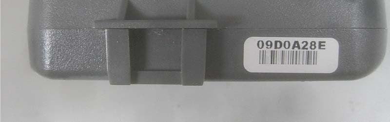
Click to zoom
Application Details
- Equipment Class
- DSC - Part 15 Security/Remote Control Transmitter
- Date of Grant
- Mar 19, 2014
- Application Purpose
- Original Equipment
- Date of Application
- Mar 19, 2014
- Equipment Note
- GPS Tracking Device
- Frequency Range
- 433.92000000 - 433.92000000
- Country
- United States
Documents & Files
Document Text
Text extracted from the exhibit documents filed with the FCC. Open a document above to read the original.
Users Manual
1 UniTrak USER’S GUIDE PRODUCT OVERVIEW The Sentinel UniTrak 1-Piece Global Positioning Satellite device is the latest addition to our TrakSeries line of offender supervision products. Sentinel’s 1- Piece GPS unit is a device that is securely attached to the program participant’s ankle, which is worn for the duration of the participant’s time in the program— providing continuous tracking of the participant’s movements while away from the residence. UniTrak has the capability of operating on either CDMA or GSM networks, and as a Sentinel advantage, UniTrak can also provide redundant residential radio frequency monitoring through the use of our Platinum home- based receiver. This design allows for the use of our “Redundant GPS over RF” tracking and monitoring model that eliminates the common issues found in other GPS units. UniTrak’s Features UniTrak provides more than thirty (30+) hours of continuous monitoring service on a single charge, built-in vibration motors for alert purposes, and locally stores more than 100 geographic zones in the unit. For battery recharging, the device utilizes a power cord with a special magnetized adaptor that connects to the bottom of the device with a break-away design that prevents any damage to the device or cord. Sentinel’s 1-piece GPS device is made of a hypoallergenic, non-irritating plastic and consists of only three (3) pieces - the GPS unit, the ankle strap, and the holding bracket; it weighs a mere 6.5 ounces fully assembled. UniTrak is installed on the program participant—without the use of tools—in less than five (5) minutes due to the unique snap-and-lock design Sentinel uses in its TrakSeries offender supervision equipment. This secure locking mechanism is also part of the UniTrak’s tamper features; the unit cannot be unlocked or removed without leaving “tell-tale” signs of the tamper efforts of the program participant. Sentinel’s UniTrak is designed to overcome tamper attempts in a variety of ways. Once the device is properly installed on the participant’s ankle, UniTrak cannot (over) be removed unless the strap is cut or severed, thereby compromising the strap and generating a tamper alert. Also, if the offender attempts to remove the GPS unit itself from the strap harness, a tamper alarm will also be generated. Violations are immediately processed in real-time, except for passive programs that involve historical reporting timeframes. Notification timelines are determined by the agency, and Sentinel is capable of notifying authorized staff immediately or within a designated time-frame. All client participant information is maintained in SenTrak, our secure web-based monitoring application database. UniTrak’s Tracking Capabilities Sentinel’s secure, web-based monitoring system, SenTrak, is capable of continuously initiating, receiving, and storing all calls and voice responses of the participant as well as the data sent by the field monitoring equipment; all events are recorded with the date and time of each occurrence. All field units report-in either via landline or cellular networks to our Monitoring Center. Our GPS tracking units communicate with the Global Positioning System satellite constellation operated by the United States Federal Government. The UniTrak has a twelve (12) channel GPS receiver to continuously track satellites – the best acquisition capability in the GPS industry; other vendors’ GPS units utilize only three or four (3 or 4) in order to determine their location. When in use, the GPS units relay the data via local cell towers that report into our Monitoring Center. This information is then deciphered and alerts are then sent to the designated personnel. All of our GPS customers are supported by our continuous operations (24/7) Monitoring Center personnel. TABLE OF CONTENTS Chapter 1: Technical Specifications 6 Components 10 Spec Sheet Chapter 2: Installation Process 12 Client Setup 22 Installing UniTrak 29 Connecting UniTrak and the ACU Chapter 3: How It Works 38 Acquiring Points 39 Tracking Modes 1 TECHNICAL SPECIFICATIONS 6CHAPTER ONE TECHNICAL SPECIFICATIONS 1 2 3 4 5 6 7 8 9 10 7 1 LED lights notify offender of status and messages A static red light (non-blinking) means there are two (2) hours of battery life remaining A static yellow light (non-blinking) means there are six (6) hours of battery life remaining A static green light (non-blinking) means the unit is in TAMPER mode A red and yellow light will blink at the same time when the unit is plugged in to charge; the red light will continue to blink while the unit is charging The red light remains on and blinking for up to one (1) hour after the unit has been unplugged 2 Minimalist, ergonomic design to maximize comfort 3 On-board memory stores zones and tracking data 4 Industry leading battery life of 30+ hours 5 Buckle-less strap for easy installation without the need for tools 6 Comfortable, hypoallergenic strap 7 Durable, water- and shock-resistant design 8 Tamper alert technology 9 Easy to use “break-away design” charging port 10 Vibration motor for alert purposes A. B. C. D. E. COMPONENTS CHAPTER ONE TECHNICAL SPECIFICATIONS 8CHAPTER ONE TECHNICAL SPECIFICATIONS Sentinel’s one-piece GPS device is made of a hypoallergenic, non-irritating plastic and consists of only three (3) pieces - the GPS unit, the ankle strap, and the holding bracket; it weighs a mere 6.5 ounces fully assembled. 9CHAPTER ONE TECHNICAL SPECIFICATIONS The UniTrak GPS unit is made of a non-irritating, polycarbonate ABS plastic. The unit is sealed and designed to operate under normal atmospheric conditions and temperatures. It is 100% water- proof and shock-resistant and allows a participant to conduct all normal daily activities, including showering, without affecting the unit’s operation. The GPS unit is easily cleaned / sanitized with a germicidal cleaner, such as do-it ALL™. UniTrak’s ankle-strap is 14.5” long and adjustable in ½” increments. It is made of a proprietary, hypoallergenic El…
Text truncated - open the document above for the full version.
ID Label/Location Info
ID Label and Location Information: Sample Label Sample Location
RF Exposure Info
Radio Frequency Exposure Assessment The power maximum power levels for the CC864DUAL module employed in the design are extracted from the FCC Grant of Authorization dated 03/10/2011 by Nemko Canada Inc. The measured minimum distance between the antenna and the ankle is 30 mm. The figure below demonstrates the minimum separation between the ankle skin point of contact with the device and the nearest point of the antenna. The skin point of contact is the strap back plate and the antenna is measured to be 30 mm from that point. The Telit module is only powered for a short period of time every ten minutes as controlled by the firmware. Firmware in the unit restricts the transmission in order to conserve battery and remain within the acceptable SAR limitations. The maximum data packet payload is 1100 bytes. Assuming a worst case transmission overhead of 100 percent at the minimum EVDO data transfer rate (38,400 bits per second), the modem would be transmitting for a total of 0.46 seconds. This would translate to a duty cycle of 0.07 percent since the transmissions occur at a minimum of 10 minutes (600 seconds) apart. The firmware restricts the total on the air time to a maximum of 10 seconds per transmission as a safeguard to minimize battery consumption. This translates to a worst case duty cycle of 1.7% maximum (10 seconds every ten minutes maximum). The worst case duty cycle of 1.7 percent is then used in accordance with the SAR Exclusion Power Thresholds Table for 100MHZ-6GHZ and distance less than 50mm in Appendix A of FCC Document “447498 D01 General RF Exposure Guidance v05r02”. 10-g Extremity SAR Test Exclusion Power Thresholds apply since the device must only be worn on the ankle. The table below shows the results of the required calculation. The 1.7 percent maximum duty cycle results in calculated limits below the 10g extremity SAR exclusion limit for both frequency bands. SKIN CONTACT SURFACE ANTENNA Frequency Power MinimumDuty Cycle10g Extremity SAR exclusion limit (MHZ) (mW)d (mm)dc (%)7.5 848 290301.74.79 1908 287301.77.10 Power On Spacing (min) 10 minutes 600Seconds On Air (max) 10 Seconds Duty Cycle (%) 1.7 10g Extremity SAR Exclusion Calculation
Test Report
This report contains a total of 45 pages and may be reproduced in full only. Partial reproduction may only be done with the written consent of CKC Laboratories, Inc. Sentinel Offender Services ADDENDUM TO TEST REPORT 95337-14 Electronic Personnel Monitoring Unit Model: Unitrak Tested To The Following Standards: FCC Part 15 Subpart C Section(s) 15.207 & 15.231 Report No.: 95337-14A Date of issue: March 17, 2014 This test report bears the accreditation symbol indicating that the testing performed herein meets the test and reporting requirements of ISO/IEC 17025 under the applicable scope of EMC testing for CKC Laboratories, Inc. We strive to create long-term, trust based relationships by providing sound, adaptive, customer first testing services. We embrace each of our customers’ unique EMC challenges, not as an interruption to set processes, but rather as the reason we are in business. Page 2 of 45 Report No.: 95337-14A TABLE OF CONTENTS Administrative Information .......................................................................................................................... 3 Test Report Information ............................................................................................................................................ 3 Revision History ......................................................................................................................................................... 3 Report Authorization ................................................................................................................................................. 3 Test Facility Information ............................................................................................................................................ 4 Software Versions ...................................................................................................................................................... 4 Site Registration & Accreditation Information .......................................................................................................... 4 Summary of Results ................................................................................................................................................... 5 Conditions During Testing.......................................................................................................................................... 5 Equipment Under Test ............................................................................................................................................... 6 Peripheral Devices ..................................................................................................................................................... 6 FCC Part 15 Subpart C ................................................................................................................................... 7 15.207 AC Conducted Emissions ................................................................................................................................ 7 15.31(e) Voltage Variations ..................................................................................................................................... 15 15.231(a) Types of Momentary Signals ................................................................................................................... 18 15.231(b) Field Strength of Fundamental and Spurious Emission ........................................................................... 23 15.231(c) -20dB Occupied Bandwidth ..................................................................................................................... 39 15.231(d) Frequency Stability .................................................................................................................................. 43 15.231(e) Reduced Field Strengths .......................................................................................................................... 43 Supplemental Information .......................................................................................................................... 44 Measurement Uncertainty ...................................................................................................................................... 44 Emissions Test Details .............................................................................................................................................. 44 Page 3 of 45 Report No.: 95337-14A ADMINISTRATIVE INFORMATION Test Report Information REPORT PREPARED FOR: REPORT PREPARED BY: Sentinel Offender Services 220 Technology Drive, Suite 200 Irvine, CA 92618 Morgan Tramontin CKC Laboratories, Inc. 5046 Sierra Pines Drive Mariposa, CA 95338 Representative: Trevor Coolidge Project Number: 95337 Customer Reference Number: 38492 DATE OF EQUIPMENT RECEIPT: February 3, 2014 DATE(S) OF TESTING: February 3 - 4, 2014 March 14-18, 2014 Revision History Original: Testing of the Electronic Personnel Monitoring Unit, Unitrak to FCC Part 15 C Section 15.207 & 15.231. Addendum A: To add conducted emissions and additional fundamental field strength test data with the EUT connected to an AC/DC adaptor. Report Authorization The test data contained in this report documents the observed testing parameters pertaining to and are relevant for only the sample equipment tested in the agreed upon operational mode(s) and configuration(s) as identified herein. Compliance assessment remains the client’s responsibility. This report may not be used to claim product endorsement by A2LA or any government agencies. This test report has been authorized for release under quality control from CKC Laboratories, Inc. Steve Behm Director of Quality Assurance & Engineering Services CKC Laboratories, Inc. Page 4 of 45 Report No.: 95337-14A Test Facility Information Our laboratories are configured to effectively test a wide variety of product types. CK…
Text truncated - open the document above for the full version.
Test Setup Photos
X - Axis Y - Axis Z - Axis Back View
Contact Information
Applicant
Michael Bermingham(Sr. Director Engineering)
Technical Contact
Sentinal Offender Services, LLCStephen Durana
[email protected]949-453-1550
201 Technology Drive · Irvine, California · United States
Non-Technical Contact
Sential Offender Services, LLC.Han Kintsch
[email protected]949-453-1550
Test Firm
CKC Laboratories, Inc.Steve Behm
Technical Specifications
| # | Rule Parts | Frequency Range | Power Output |
|---|---|---|---|
| 1 | 15.231(e) | 433.92 MHz - 433.92 MHz | - |