VZVBUZZ02Wireless Buzz!TM Buzzers
NAMTAI ELECTRONIC(SHENZHEN) COMPANY LIMITED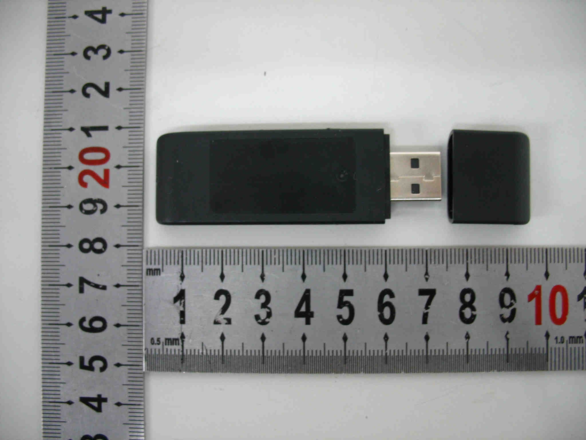
Click to zoom
Application Details
- Equipment Class
- DTS - Digital Transmission System
- Date of Grant
- Apr 14, 2008
- Application Purpose
- Original Equipment
- Date of Application
- Apr 14, 2008
- Equipment Note
- Wireless Buzz!TM Buzzers
- Frequency Range
- 2402.00000000 - 2481.00000000
- Country
- China
Documents & Files
Document Text
Text extracted from the exhibit documents filed with the FCC. Open a document above to read the original.
Users Manual
Wireless Buzz!™ Buzzers Manual Approved – 08/02/08 Instruction Manual Before using this product, carefully read this manual and retain it for future reference. These Wireless Buzz!™ Buzzers are designed for use with the PlayStation®2 console and the PLAYSTATION®3 system. Product Contents <<Designer’s Note: please insert a diagram of a Buzz!™ Buzzer and a diagram of the USB receiver>> • Four Wireless Buzz!™ Buzzers. • One USB receiver with receiver cap. • Eight AA alkaline batteries. Warning To avoid potential electric shock or starting a fire, do not expose this product to rain or moisture. Precautions Safety This product has been designed with the highest concern for safety. However, any electrical device, if used improperly, has the potential for causing fire, electric shock or personal injury. To ensure accident-free operation, be sure to follow these guidelines: • Observe all warnings, precautions and instructions. • Do not use the product if it functions in an abnormal manner. • If the product does not function properly, call the appropriate PlayStation® customer service number which can be found: – within every PlayStation®2 and PLAYSTATION®3 format software manual; and – on our website at playstation.com • This product contains small parts, which, if removed, may present a choking hazard to children. Use and Handling • Do not expose the product to high temperatures, high humidity or direct sunlight. • Operate in an environment where temperatures range between 5°C and 35°C. • Do not allow liquid or small particles to get into the product. • Do not put heavy objects on the product. • Never disassemble or modify the product. • Do not throw or drop the product, or physically damage it in any way. • Do not touch the product’s metal parts or insert foreign objects into its USB connector. Cleaning the Wireless Buzz!™ Buzzers Dust may build up on the product after an extended period of time. • Before cleaning the product, disconnect it from the PlayStation®2 console or the PLAYSTATION®3 system for safety. • Wipe the product’s surface with a soft, dry cloth. • The product should be cleaned by an adult, or cleaned under close adult supervision. • Do not use a moistened cloth to clean the product as water may cause it to malfunction. • Do not use benzene, paint thinner or other chemicals as these may damage the product. • When using a commercially available cleaning cloth, follow the instructions supplied with the cloth. AA Alkaline Batteries • Do not throw the batteries into fire. • Do not carry the batteries with coins or other metallic objects. The batteries can generate heat if their positive and negative terminals come into accidental contact with metallic objects. • Do not mix new batteries with old ones. • Do not use different types of batteries together. • When you are not going to use the product for a long time, remove the batteries to avoid damage from battery leakage and corrosion. • If battery leakage occurs, wipe off any deposit and install new batteries. If the deposit sticks to you, wipe it off thoroughly. Connecting the Wireless Buzz!™ Buzzers <<Designer’s Note: insert diagram showing how to connect the USB receiver to a PS2™ or PS3™>> USB receiver • Remove the receiver cap from the USB receiver and insert its USB connector into any USB connector on the front of the PlayStation®2 console or the PLAYSTATION®3 system. • Turn on the PlayStation®2 console or the PLAYSTATION®3 system. Wireless Buzz!™ Buzzers <<Designer’s Note: insert diagram of a Buzz!™ Buzzer ensuring that the slide switch (with POWER and LOCK settings) and battery cover are labelled>> • Before using a Buzz!™ Buzzer, carefully remove its battery cover and insert two AA alkaline batteries (supplied). • To turn a Buzz!™ Buzzer on, push the POWER/LOCK switch briefly towards the POWER position. When a Buzz!™ Buzzer is activated, its blue LED indicator will flash rapidly eight times. • To turn a Buzz™ Buzzer off, push the POWER/LOCK switch briefly towards the POWER position. The Buzz™ Buzzer’s blue LED indicator will flash slowly four times to indicate that it has turned off. NOTE: A Buzz!™ Buzzer will turn off automatically if left idle for 20 minutes. • When using a Buzz!™ Buzzer, push the POWER/LOCK switch into the LOCK position to make sure it doesn’t turn off accidentally. Pairing the Wireless Buzz!™ Buzzers These Wireless Buzz!™ Buzzers have already been paired with the supplied USB receiver. If a replacement Buzz!™ Buzzer is introduced, all four Wireless Buzz!™ Buzzers must be paired with the USB receiver again. • Push the POWER/LOCK switch on all four Wireless Buzz!™ Buzzers into the POWER position and hold it for four seconds, until their blue LED indicators glow continuously. Be sure to perform this operation within two metres of the PlayStation®2 console or the PLAYSTATION®3 system. • Press and hold the BIND button on the USB receiver. Its blue LED indicator will glow and flash once as each Buzz!™ Buzzer successfully pairs. • As each Buzz!™ Buzzer pairs with the USB receiver, its blue LED indicator and red Buzz!™ button will flash briefly, indicating a successful connection and pairing. To test the connection, press any button and the blue LED indicator on the Buzz!™ Buzzer and the USB receiver will flash briefly. • The USB receiver will pair with a maximum of four Wireless Buzz!™ Buzzers. To play with five to eight Wireless Buzz!™ Buzzers, a second USB receiver is required. Using the Wireless Buzz!™ Buzzers The usage and function of the product may vary depending on the software in use. See the appropriate software manual for details. Troubleshooting If you experience any difficulties while using the product, please call the appropriate PlayStation® customer service number which can be found: – within every PlayStation®2 and PLAYSTATION®3 format software manual; and – on our website at playstation.com Specifications Interface (USB receiver and PS2™/PS3™) USB type 1.1 Interface (Buzz!™ Buzzer and USB recei…
Text truncated - open the document above for the full version.
External Photos
Page 1 of 2 Type Designation: SLEH-00069(USB Receiver) Report Number: 17008737 002 Figure 1. Figure 2. Page 2 of 2 Type Designation: SLEH-00069(USB Receiver) Report Number: 17008737 002 Figure 3.
Internal Photos
Page 1 of 2 Type Designation: SLEH-00069(USB Receiver) Report Number: 17008737 002 Figure 1. Figure 2. Page 2 of 2 Type Designation: SLEH-00069(USB Receiver) Report Number: 17008737 002 Figure 3.
Operational Description
Wireless Buzz!™ Buzzers operation descriptions 1) The Wireless Buzz!™ Buzzers is a bi-direction communication application, one USB Receiver can be paired with 4 Pods at most. The USB Receiver and Pods are bound as a fixed system. 2) The USB Receivers is master device at all time. The Pods are slave devices. The USB Receiver transmits request signal actively always. The Pods keep as receiving status always before it receives a request from USB Receiver. If a Pod receives a request from the USB Receiver, it respond a acknowledge signal to USB Receiver immediately 3) The time slot of transmitting a request signal and receiving an acknowledgement of Pods is 0.75ms. 4) We use time-sharing technology to let all 5 devices (1 USB Receiver and 4 Pods) working in a same channel. As the USB Receiver poll the Pods very quickly, the end user seems that 4 Pod are communicated with USB Receiver simultaneously. Each Pod has one ID
Schematics
PDF 文件使用 "pdfFactory Pro" 试用版本创建 www.fineprint.cn
Test Report
Produkte Products Prüfbericht - Nr.: Test Report No. 17008737 002 Seite 2 von 49 Page 2 of 49 TEST SUMMARY 5.1 ANTENNA REQUIREMENT RESULT: Passed 5.2 PEAK OUTPUT POWER RESULT: Passed 5.3 6DB BANDWIDTH RESULT: Passed 5.4 100KHZ BANDWIDTH OF FREQUENCY BAND EDGE RESULT: Passed 5.5 MAXIMUM POWER DENSITY RESULT: Passed 5.6 SPURIOUS EMISSION RESULT: Passed 5.7 CONDUCTED EMISSIONS RESULT: Passed 5.8 RADIATED EMISSIONS RESULT: Passed Produkte Products Prüfbericht - Nr.: Test Report No. 17008737 002 Seite 3 von 49 Page 3 of 49 Contents 1. GENERAL REMARKS......................................................................................................... 4 1.1 COMPLEMENTARY MATERIALS.......................................................................................... 4 2. TEST SITES...................................................................................................................... 4 2.1 TEST FACILITIES............................................................................................................... 4 2.2 LIST OF TEST AND MEASUREMENT INSTRUMENTS............................................................... 5 2.3 TRACEABILITY.................................................................................................................. 6 2.4 CALIBRATION................................................................................................................... 6 2.5 MEASUREMENT UNCERTAINTY........................................................................................... 6 2.6 LOCATION OF ORIGINAL DATA........................................................................................... 6 2.7 STATUS OF FACILITY USED FOR TESTING........................................................................... 6 3. GENERAL PRODUCT INFORMATION.................................................................................... 7 3.1 PRODUCT FUNCTION AND INTENDED USE........................................................................... 7 3.2 RATINGS AND SYSTEM DETAILS........................................................................................ 7 3.3 INDEPENDENT OPERATION MODES.................................................................................... 8 3.4 NOISE GENERATING AND NOISE SUPPRESSING PARTS....................................................... 8 3.5 SUBMITTED DOCUMENTS.................................................................................................. 8 4. TEST SET-UP AND OPERATION MODES.............................................................................. 8 4.1 PRINCIPLE OF CONFIGURATION SELECTION........................................................................ 8 4.2 TEST OPERATION AND TEST SOFTWARE............................................................................ 8 4.3 SPECIAL ACCESSORIES AND AUXILIARY EQUIPMENT.......................................................... 9 4.4 COUNTERMEASURES TO ACHIEVE EMC COMPLIANCE......................................................... 9 4.5 TEST SETUP DIAGRAM......................................................................................................9 5. TEST RESULTS OF TRANSMITTER.................................................................................... 11 5.1 ANTENNA REQUIREMENT................................................................................................ 11 5.2 PEAK OUTPUT POWER.................................................................................................... 12 5.3 6DB BANDWIDTH............................................................................................................ 15 5.4 100KHZ BANDWIDTH OF FREQUENCY BAND EDGE........................................................... 18 5.5 MAXIMUM POWER DENSITY............................................................................................. 21 5.6 SPURIOUS EMISSION....................................................................................................... 24 5.7 CONDUCTED EMISSIONS.................................................................................................. 37 5.8 RADIATED EMISSIONS..................................................................................................... 40 6. PHOTOGRAPHS OF THE TEST SET-UP.............................................................................. 47 Produkte Products Prüfbericht - Nr.: Test Report No. 17008737 002 Seite 4 von 49 Page 4 of 49 7. LIST OF TABLES............................................................................................................. 49 8. LIST OF PHOTOGRAPHS.................................................................................................. 49 1. General Remarks 1.1 Complementary Materials None 2. Test Sites 2.1 Test Facilities TÜV Rheinland (Guangdong) Ltd. EMC Laboratory Guangzhou Auto Market, Yuan Gang Section of Guangshan Road, Guangzhou, P.R. China Produkte Products Prüfbericht - Nr.: Test Report No. 17008737 002 Seite 5 von 49 Page 5 of 49 2.2 List of Test and Measurement Instruments Table 1: List of Test and Measurement Equipment Kind of Equipment Manufacturer Type S/N Calibrated until For Radio Test Suite Spectrum Analyzer Rhode & Schwarz FSP30 100286 2008-09-16 Spurious Emission Test and Radiated Emission Test EMI Test Receiver Rohde &Schwarz ESCI3 1.807 2009-01-25 Trilog-Broadband Antenna Schwarzbeck VULB916 8 209 2009-05-08 3m Semi-anechoic chamber Albatross Projects N/A N/A 2011-03-16 Horn Antenna EMCO 21642 63042-766 (3160-09) 2008-07-25 Double-Ridged Waveguide Horn Antenna Rohde &Schwarz HF 906 100385 2009-07-09 Conducted Emission Test EMI Test Receiver Rohde & Schwarz ESCS30 830245/009 2008-08-12 Two-Line V-Network Rohde & Schwarz ESH3-Z5 100308 2008-08-12 Produkte Products Prüfbericht - Nr.: Test Report No. 17008737 002 Seite 6 von 49 Page 6 of 49 2.3 Traceability All measurement equipment calibrations are traceable to NIST or where calibration is performed outside the …
Text truncated - open the document above for the full version.
Test Setup Photos
Produkte Products Prüfbericht - Nr.: Test Report No. 17008737 002 Seite 47 von 49 Page 47 of 49 6. Photographs of the Test Set-Up Photograph 1: Set-up for Conducted Emissions Photograph 2: Set-up for Radiated Emissions Produkte Products Prüfbericht - Nr.: Test Report No. 17008737 002 Seite 48 von 49 Page 48 of 49 Photograph 3: Set-up for Spurious Emissions test (1GHz – 18GHz) Photograph 4: Set-up for Spurious Emissions test (18GHz – 26GHz)
Contact Information
Applicant
Lily Yang(QA Manager)
Test Firm
TUV Rheinland (GuangDong) Ltd.Yuxin Huang
Technical Specifications
| # | Rule Parts | Frequency Range | Power Output |
|---|---|---|---|
| 1 | 15C | 2.40 GHz - 2.48 GHz | 890.00 µW |
Other Applications from NAMTAI ELECTRONIC(SHENZHEN) COMPANY LIMITED
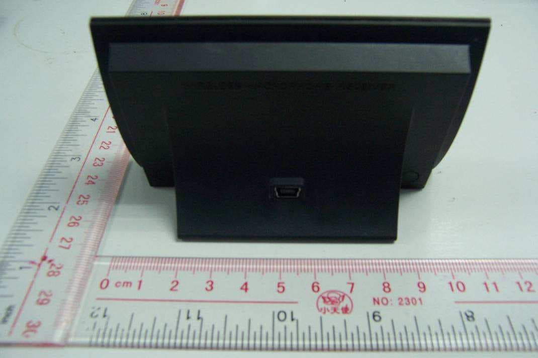
VZVWLMIC1-1
Jan 19, 2010Wireless SingStar Microphone Receiver
Equipment Class
DSS - Part 15 Spread Spectrum Transmitter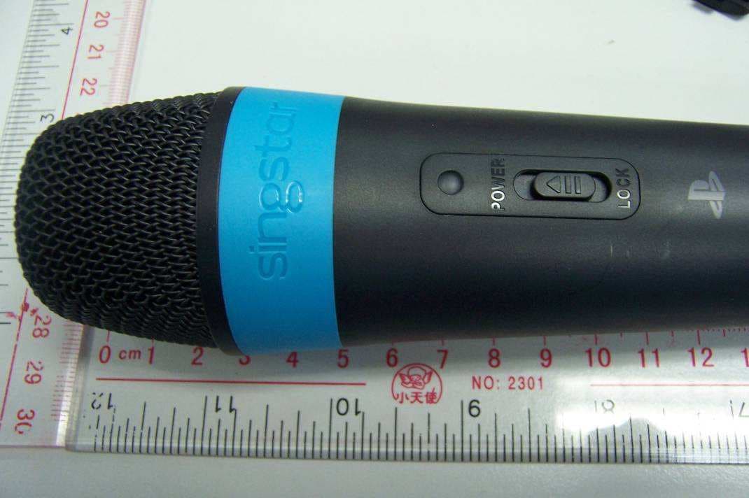
VZVWLMIC2-1
Jan 18, 2010Wireless SingStar Microphone
Equipment Class
DSS - Part 15 Spread Spectrum Transmitter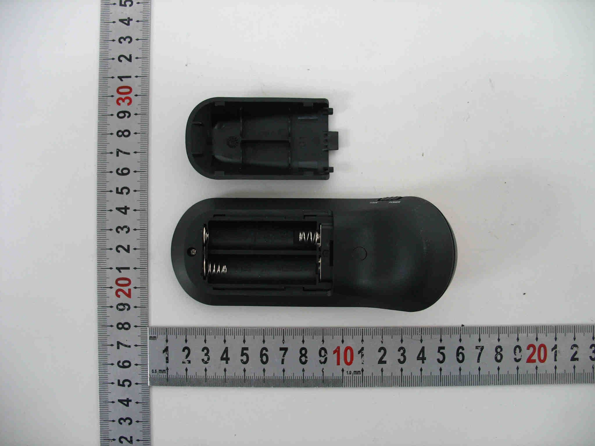
VZVBUZZ01
Apr 14, 2008Wireless Buzz!TM Buzzers
Equipment Class
DTS - Digital Transmission System