W250010Programming Wand
BIO CONTROL MEDICAL (B.C.M.) LTD.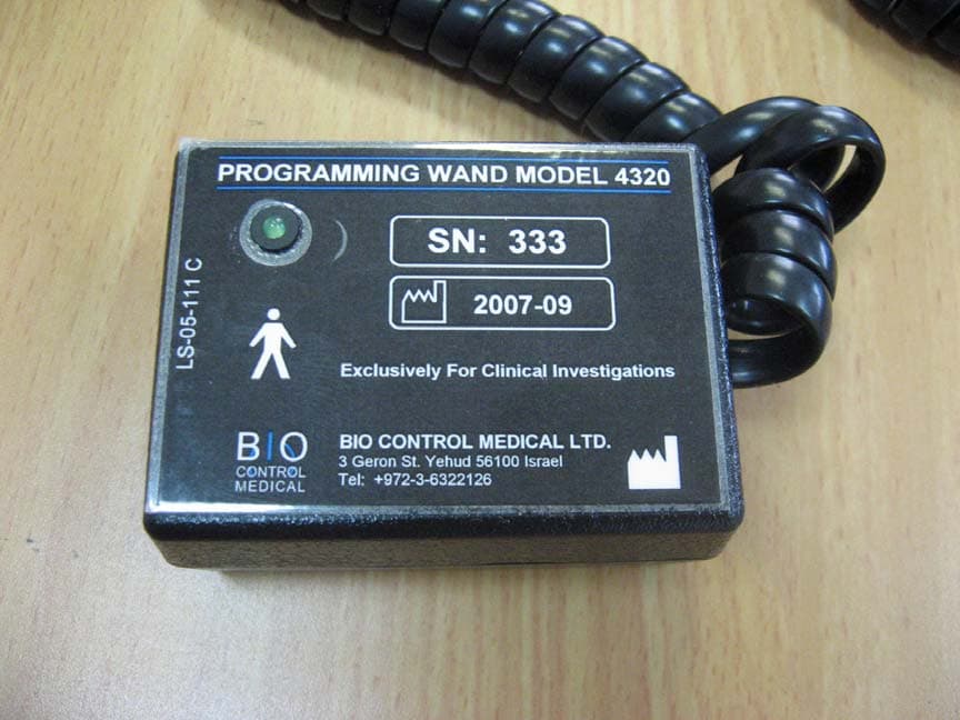
Click to zoom
Application Details
- Equipment Class
- DCD - Part 15 Low Power Transmitter Below 1705 kHz
- Date of Grant
- Feb 15, 2009
- Application Purpose
- Original Equipment
- Date of Application
- Feb 12, 2009
- Equipment Note
- Programming Wand
- Frequency Range
- 0.02700000 - 0.02700000
- Country
- Israel
Documents & Files
Document Text
Text extracted from the exhibit documents filed with the FCC. Open a document above to read the original.
Users Manual
BIOCONTROL MEDICAL BCM LTD INSTRUCTIONS FOR USE DOC NO. RU-53-001 REV. H SUBJECT: UNIFIED PHYSICIAN PROGRAMMER Page 1 of 40 MODIFICATION INSTRUCTION NO.: MODIFICATION DATE: 05/05/2008 MODIFICATION DESCRIPTION: Update to software version 1.105. ISSUED BY TITLE DATE SIGNATURE DUDU RIGLER DIRECTOR OF CLINICAL AFFAIRS 28/08/2008 A PPROVAL LIST NAME TITLE DATE SIGNATURE SHAI AYAL DIRECTOR OF DEVELOPMENT TAMIR SHEFER DIRECTOR OF QUALITY ASSURANCE RAMI BIRAN VP REGULATORY & CLINICAL AFFAIRS VERSION NAME DATE ECO NO: MODIFICATION DESCRIPTION A ARI KEREN-YAAR 06/08/2006 --- First Issue B ARI KEREN-YAAR 31/10/2006 --- Editorial Changes C ARI KEREN-YAAR 11/12/2006 --- Addition of buttons; add applicable icons and authorized representative D YITZHAK SINAI 01/02/2007 136 Update of device and software to 7.14 E LEVY ITSIK 15/03/2007 --- Changes According TO ITL Remarks. F ROMANO AVINOAM 05/05/2008 153 Update to software 1.0.105 G LEVY ITSIK 15/08/2008 KEMA 2103063 Adding battery lifetime contour; list of abbreviations; clarification of terms and warnings H RIGLER DAVID 28/12/2008 KEMA 2103063- 17.9.08 Addition of follow-up requirements; RF and FCC symbols and text Addition of ICD compliance; updating to software 1.0.14; updating troubleshooting and EMC requirements. Neurostimulator For Heart Failure Therapy UNIFIED PHYSICIAN PROGRAMMER MODEL 5300 INSTRUCTIONS FOR USE (IFU) & TD Caution: Limited by Federal Law to Investigational Use 0344 (2008) Unified Physicain Programmer IFU RU-53-001 H 4 Explanation of symbols on package labeling Symbol Explanation Symbol Explanation Contents Warning: Patient Might Be Compromised SN Serial Number Caution: possible damage to device Product Literature Note: Important Information Consult Instructions For Use Do Not Use If Package Damaged Type B Applied Part Manufacturer European Approval Mark Date Of Manufacturing On Storage Temperature Range OFF Storage & Transport Relative Humidity Range Stepping Prohibited Storage & Transport Atmospheric Pressure Range Sitting Prohibited Authorized Representative In The European Community Do Not Dispose Of. Contact BCM For Recycling. Complies with FCC part 15 Unified Physicain Programmer IFU RU-53-001 H 5 Contains RF transmitters Unified Physicain Programmer IFU RU-53-001 H 6 CONTENTS 1. DESCRIPTION 8 3. PRECAUTIONS 9 4. WARNINGs 9 5. SETTING UP THE SYSTEM 10 5.1 Charging the Physician Programmer 10 5.2 Getting started 10 5.3 General System Interface Description 12 5.3.1 The "General" Tab 12 5.3.2 The "Statistic" tab; Therapy evaluation. 14 5.3.3 The "Setting" Tab 17 6 Therapy Setting and Optimization Program 25 6.1 General 26 6.2 Therapy Optimization Goal 26 6.3 Communication rules with the patient 26 6.4 Visit Activities Flow 26 6.5 Parameter setting process 27 6.6 Instantaneous HRR evaluation and PPB/ON time change 27 7. INTERACTIONS WITH IMPLANTABLE CARDIOVERTER DEFIBRILLATORS 28 8 MAINTENANCE, HANDLING, AND STORAGE 31 8.1 Maintenance 31 8.2 Handling 31 8.3 Storage 32 9. TROUBLESHOOTING 33 10. PRODUCT INFORMATION AND SUPPORT 36 11. DISCLAIMER OF WARRANTY 36 APPENDIX A. Electromagnetic environment – guidance IEC 60601-1-2 37 Guidance and manufacturer’s declaration – electromagnetic emissions 37 Guidance and manufacturer’s declaration – electromagnetic immunity 37 Guidance and manufacturer’s declaration – electromagnetic immunity 38 Recommended separation distance 38 Recommended separation distances between portable and mobile RF communications equipment and the Physician Programmer model 5300 & CardioFit-X Ver 8.15 39 Unified Physicain Programmer IFU RU-53-001 H 7 List of Abbreviations Abbreviation Explanation BCM BioControl Medical CIS CardioFit™ Implanted Stimulator CRT-D Cardiac Resynchronization Therapy - Implantable Cardioverter - Defibrillators CSL CardioFit™ Stimulation Lead ECM Electromagnetic protection mode HR / BPM Heart Rate / Beats Per Minute ICD Implantable Cardioverter-Defibrillators, Single, or Dual chamber IHRR Instantaneous heart rate reduction ISE Intracardiac Sensing Lead NYHA New York Heart Association PPB Pulse Per Beat – The number of pulses provided by the stimulator per heartbeat PRI Pulse Repetition Interval – The distance between pulses when PPT > 1 QTP Quasitrapezoidal Pulse – Shape of the default pulse TD Technical Dossier UniPP Unified Physician Programmer VF Ventricular Fibrillation VT Ventricular Tachycardia Unified Physicain Programmer IFU RU-53-001 H 8 1. DESCRIPTION Introduction The model 5300 Unified Physician Programmer (UniPP) is used to interrogate and program the BioControl model 5000 CardioFit™ neurostimulator (the stimulator). The UniPP can retrieve data and set programmable parameters of the CardioFit™ stimulator via wireless communication. Programming is done using the CardioFit™ Physician Programmer software installed on a PC compatible laptop, a communication interface and a programming wand. The wand is the only part of the Programmer that contacts the patient. The Physician Programmer software uses the communication interface and the programming wand to convert digital output from the Laptop PC to wireless signal format that is required for communication with the stimulator (Figure 1). Figure 1 – Model 5300 Physician Programmer Specifications and user information regarding the wireless technology The CardioFit system uses a short-range (3-6 cm) inductive coupling communication scheme in frequency of 27kHz. The system is ready to communicate when green light is blinking in 1-2Hz on the programming wand. See warnings and precautions that should be exercised when using the system under Sections 3 and 4 below. Contents of package The model 5300 Physician Programmer package contains: a. One Laptop PC installed with BioControl CardioFit™ Unified Physician Programmer software version 2.0.x; b. One Communication Interface and Programming Wand (Model 4320); c. Medical grade power supply Model 4300/MPU100-106; d. Instructions For Use; Laptop PC Communication Interface Programming Wand Unified…
Text truncated - open the document above for the full version.
Cover Letter(s)
I.T.L (PRODUCT TESTING) Ltd. PRODUCT SAFETY, EMC & TELECOMS LAB. Bat-Sheva St., POB 87 LOD 71100 ISRAEL Tel. 972-8-9153100 Fax. 972-8-9153101 Email: [email protected], Web Site: http://www.itl.co.il To: Timco Engineering From: Shaike Raz Att: Reviewing Engineer Reference No: L86710.00 Date: 12 February 2009 Subject: Programming Wand Model 4320 FCC ID: W250010 Application for BioControl Medical (B.C.M.) Ltd. To Whom it my Concern, 1. The subject product is operated as part of a system comprising a laptop, interface device and the programming wand. 2. The interface device was tested and subject to the FCC DoC procedure. 3. Only the Programming Wand is subject to certification. Please contact me if you need any additional information. Regards Shaike Raz EMC Laboratory Manager EMC Laboratory ITL (Product Testing) Ltd. Kfar Bin Nun Israel Tel: +972-8-915-3100 Ext 217 Fax: +972-8-915-3101 Email: [email protected] http://www.itl.co.il
ID Label/Location Info
SN: 242 2006-12 BIO CONTROL MEDICAL LTD. 3 Geron St. Yehud 56100 Israel Tel: +972-3-6322126 LS-05-111 D Programming Wand Model 4320 0344 IN THE U.S: CAUTION - Investigational Device. Limited B y Federal Law To Investigational Use. FCC ID: W250010 This device complies with Part 15 of the FCC Rules. Operation is subject to the following two conditions: 1.This device may not cause harmful interference and 2.This device must accept any interference received, including interference that may cause undesired operation.
Test Report
Cert. No. 1152.01 Electrical (EMC) Test Report E86715.00 BioControl Medical (B.C.M.) Ltd. Page 1 of 44 DATE: 09 February 2009 1 I.T.L. (PRODUCT TESTING) LTD. FCC Radio Test Report for BioControl Medical (B.C.M.) Ltd. Equipment under test: 1. Programming Wand + 2. Communication Interface Programming Wand Model 4320 Communication Interface Model 4320 Written by: _____________________________ D. Shidlowsky, Documentation Approved by: _____________________________ A. Sharabi, Test Engineer Approved by: _____________________________ I. Raz, EMC Laboratory Manager This report must not be reproduced, except in full, without the written permission of I.T.L. (Product Testing) Ltd. This report relates only to items tested. FCC ACC M Ver 1.1 05Mayl 2000 Cert. No. 1152.01 Electrical (EMC) Test Report E86715.00 BioControl Medical (B.C.M.) Ltd. Page 2 of 44 FCC ACC M Ver 1.1 05Mayl 2000 Measurement/Technical Report for BioControl Medical (B.C.M.) Ltd. 1. Programming Wand + 2. Communication Interface FCC ID: W250010 This report concerns: Original Grant: X Class I Change: Class II Change: Equipment type: Limits used: 47CFR15 Section 15.201; 209 Measurement procedure used is ANSI C63.4-2003. Application for Certification Applicant for this device: prepared by: (different from "prepared by") Ishaishou Raz Shai Ayal ITL (Product Testing) Ltd. BioControl Medical (B.C.M.) Ltd. Kfar Bin Nun 3 Geron St. D.N. Shimshon 99780 Yahud, 56100 Israel Israel e-mail [email protected] Tel: + 972 - 3- 632 – 2126 Ext 223 Fax: + 972 - 3- 632- 2125 e-mail: [email protected] TABLE OF CONTENTS 1. GENERAL INFORMATION ------------------------------------------------------------------------------- 4 1.1 Administrative Information.................................................................................4 1.2 List of Accreditations .........................................................................................5 1.3 Product Description ...........................................................................................6 1.4 Test Methodology..............................................................................................6 1.5 Test Facility .......................................................................................................6 1.6 Measurement Uncertainty .................................................................................6 2. SYSTEM TEST CONFIGURATION--------------------------------------------------------------------- 7 2.1 Justification........................................................................................................7 2.2 EUT Exercise Software .....................................................................................7 2.3 Special Accessories ..........................................................................................7 2.4 Equipment Modifications ...................................................................................7 2.5 Configuration of Tested System ........................................................................8 3. CONDUCTED EMISSION DATA------------------------------------------------------------------------ 9 3.1 Test Specification ..............................................................................................9 3.2 Test Procedure..................................................................................................9 3.3 Measured Data..................................................................................................9 3.4 Test Instrumentation Used, Conducted Measurement ...................................14 4. FIELD STRENGTH OF FUNDAMENTAL ------------------------------------------------------------15 4.1 Test Specification ............................................................................................15 4.2 Test Procedure................................................................................................15 4.3 Measured Data................................................................................................15 4.4 Test Instrumentation Used, Field Strength of Fundamental ...........................18 5. SPURIOUS RADIATED EMISSION, 9 KHZ – 30 MHZ -------------------------------------------19 5.1 Test Specification ............................................................................................19 5.2 Test Procedure................................................................................................19 5.3 Measured Data................................................................................................19 5.4 Test Instrumentation Used, Radiated Measurements ....................................21 5.5 Field Strength Calculation ...............................................................................21 6. SPURIOUS RADIATED EMISSION 30 – 1000 MHZ----------------------------------------------22 6.1 Test Specification ............................................................................................22 6.2 Test Procedure................................................................................................22 6.3 Test Data .........................................................................................................23 6.4 Test Instrumentation Used, Radiated Measurements ....................................28 6.5 Field Strength Calculation ...............................................................................29 7. SPURIOUS RADIATED EMISSION ABOVE 1 GHZ ----------------------------------------------30 7.1 Radiated Emission Above 1 GHz....................................................................30 7.2 Test Data .........................................................................................................31 7.3 Test Instrumentation Used, Radiated Measurements Above 1 GHz ..............36 8. APPENDIX A - CORRECTION FACTORS ----------------------------------------------------------37 8.1 Correction factors for CABLE ..........................…
Text truncated - open the document above for the full version.
Test Setup Photos
Programming Wand Programming Wand
Contact Information
Applicant
Shai Ayal
Test Firm
Israel Testing LaboratoriesIIan Cohen
Technical Specifications
| # | Rule Parts | Frequency Range | Power Output |
|---|---|---|---|
| 1 | 15C | 0.027 MHz - 0.027 MHz | - |
Other Applications from BIO CONTROL MEDICAL (B.C.M.) LTD.
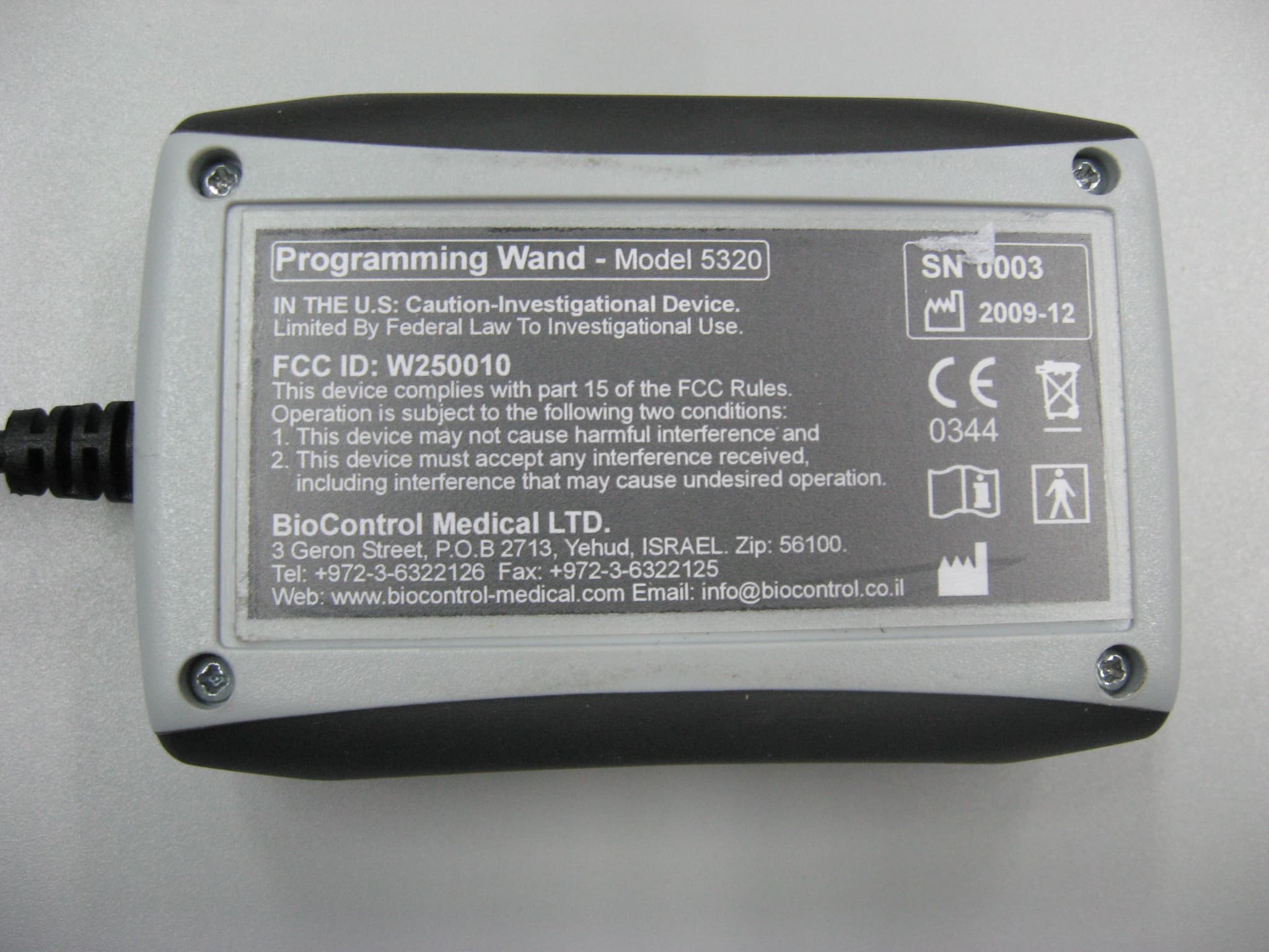
W250020
Apr 08, 2010PROGRAMMING WAND
Equipment Class
DCD - Part 15 Low Power Transmitter Below 1705 kHz