W38-CT500CT500 Electric Vehicle Charging Station
ChargePoint, Inc.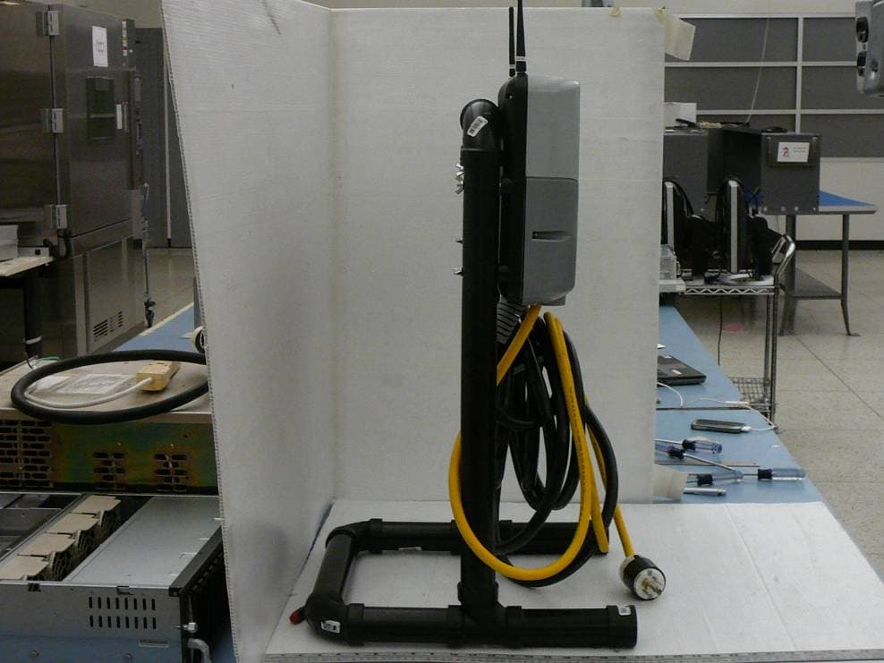
Click to zoom
Application Details
- Equipment Class
- DXX - Part 15 Low Power Communication Device Transmitter
- Date of Grant
- Nov 05, 2010
- Application Purpose
- Original Equipment
- Date of Application
- Nov 05, 2010
- Equipment Note
- CT500 Electric Vehicle Charging Station
- Frequency Range
- 13.56000000 - 13.56000000
- Company
- ChargePoint, Inc.
- Country
- United States
Documents & Files
Document Text
Text extracted from the exhibit documents filed with the FCC. Open a document above to read the original.
Users Manual
CT500 ChargePoint ® Networked Charging Station Installation Guide Part Number: 75-001024-01 Revision: 1.0 Coulomb Technologies Inc. 1692 Dell Ave. Campbell, CA 95008-6901 USA US toll free: +1-877-370-3802 www.coulombtech.com www.mychargepoint.net by Coulomb Technologies ® Safety and compliance This document provides instructions to install the ChargePoint ® Charging Station and should not be used for any other product. Before installing the ChargePoint ® Charging Station, you should review this manual carefully and consult with a licensed contractor, licensed electrician and trained installation expert to ensure compliance with local building practices, climate conditions, safety standards, and state and local codes. The ChargePoint ® Charging Station should be installed only by a licensed contractor and a licensed electrician and in accordance with all local and national codes and standards. The ChargePoint ® Charging Station should be inspected by a qualified installer prior to the initial use. Under no circumstances will compliance with the information in this manual relieve the user of his/her responsibility to comply with all applicable codes or safety standards. This document describes the most commonly-used installation and mounting scenarios. If situations arise in which it is not possible to perform an installation following the procedures provided in this document, contact Coulomb Technologies. Coulomb Technologies is not responsible for any damages that may occur resulting from custom installations that are not described in this document. No accuracy guarantee Reasonable effort was made to ensure that the specifications and other information in this manual are accurate and complete at the time of its publication. However, the specifications and other information in this manual are subject to change at any time without prior notice. Warranty information and disclaimer Your use of, or modification to, the ChargePoint ® Charging Station in a manner in which the ChargePoint ® Charging Station is not intended to be used or modified will void the limited warranty. Other than any such limited warranty, the Coulomb products are provided “AS IS,” and Coulomb and its distributors expressly disclaim all implied warranties, including any warranty of design, merchantability, fitness for a particular purposes and non-infringement, to the maximum extent permitted by law. Limitation of liability IN NO EVENT SHALL COULOMB TECHNOLOGIES, INC. OR ITS AUTHORIZED DISTRIBUTORS BE LIABLE FOR ANY INDIRECT, INCIDENTAL, SPECIAL, PUNITIVE, OR CONSEQUENTIAL DAMAGES, INCLUDING WITHOUT LIMITATION, LOST PROFITS, LOST DATA, LOSS OF USE, COST OF COVER, OR LOSS OR DAMAGE TO THE CHARGEPOINT ® CHARGING STATION, ARISING OUT OF OR RELATING TO THE USE OR INABILITY TO USE THIS MANUAL, EVEN IF COULOMB TECHNOLOGIES, INC. OR ITS AUTHORIZED DISTRIBUTORS HAVE BEEN ADVISED OF THE POSSIBILITY OF SUCH DAMAGES. Copyright and Trademarks ©2010 Coulomb Technologies, Inc. All rights reserved. This material is protected by the copyright laws of the United States and other countries. It may not be modified, reproduced or distributed without the prior, express written consent of Coulomb Technologies, Inc. CHARGEPOINT is a U.S. registered trademark and service mark of Coulomb Technologies, Inc. All other products or services mentioned are the trademarks, service marks, registered trademarks or registered service marks of their respective owners. Coulomb Technologies has filed several patent applications. IMPORTANT SAFETY INSTRUCTIONS This Installation Guide contains important instructions that must be followed during installation of the CT500. Warnings: • The CT500 must be connected to a grounded, metal, permanent wiring system; or an equipment grounding conductor must be run with the circuit conductors and connected to the CT500’s grounding terminal or lead. • The CT500 must be installed by a qualified electrician and in accordance with all local electrical codes and ordinances. • Read all instructions before installing the CT500. • Adult supervision is required when using the CT500 near children. • Do not operate a CT500 with a visibly damaged cable. Contact Coulomb Technologies immediately. • Do not operate a CT500 if the enclosure or the EV connector is broken, cracked, open, or shows any other signs of damage. Contact Coulomb Technologies immediately. • Do not put fingers into the EV connector • Do not install the CT500 near flammable, explosive, or combustible materials. • Do not operate the CT500 in temperatures outside its operating range of -22°F to 122°F (-30°C to +50°C). • The CT500 contains no user-serviceable parts. Do not attempt to repair or service the CT500 yourself. If the CT500 requires servicing, contact Coulomb Technologies. • Ensure that the CT500’s charging cable is positioned so it will not be stepped on, tripped over, or subjected to damage or stress. SAVE THESE INSTRUCTIONS Cleaning the CT500 Do not use cleaning solvents to clean any of the CT500’s components. The outside of the CT500, the charging cable, and the connector end of the charging cable should be regularly wiped with a clean dry cloth to remove any accumulation of dust and dirt. FCC Declaration of Conformity This device complies with Part 15 of the FCC rules. Operation is subject to the following two conditions: (1) This device may not cause harmful interference, and (2) this device must accept any interference received, including interference that may cause undesired operation. Radio and Television Interference The equipment described in this manual has been designed to protect against Radio Frequency Interference (RFI). However, there are some instances where high powered radio signals or nearby RF-producing equipment (such as digital phones, RF communications equipment, etc.) could affect operations. If interference to your CT500 is suspected, relocate or turn off nearby electrical appliances during charging, before contacting Coulomb Technolo…
Text truncated - open the document above for the full version.
Cover Letter(s)
FCC Confidential Authorization September 7, 2010 FEDERAL COMMUNICATIONS COMMISSIONS Authorization and Evaluation Division 7435 Oakland Mills Road Columbia, MD 21046 Subject: Confidentiality Request regarding application for certification of FCC ID: W38-CT500 In accordance with Sections 0.457 and 0.459 of the Commission’s Rules, Coulomb Technologies Inc., hereby requests long-term confidential treatment of information accompanying this application as outlined below: • Block Diagram • Schematics • Operation Description The above materials contain proprietary and confidential information not customarily released to the public. The public disclosure of these materials provides unjustified benefits to its competitors in the market. Sincerely, Gary Eldridge, P.E. Regulatory Compliance Manager Phone: 408 718-3781 [email protected] Coulomb Technologies, Inc. 1692 Dell Ave. Campbell CA 95008-6901
External Photos
Coulomb Technologies, Inc. FCC ID: W38-CT500, IC: 8854A-CT500 Report Number: R1008201-225 Page 29 of 40 FCC Part15.225/RSS 210 Test Report 10 EXHIBIT C - EUT PHOTOGRAPHS 10.1 EUT - Front View 10.2 EUT - Back View Coulomb Technologies, Inc. FCC ID: W38-CT500, IC: 8854A-CT500 Report Number: R1008201-225 Page 30 of 40 FCC Part15.225/RSS 210 Test Report 10.3 EUT - Side View 1 10.4 EUT - Side View 2
ID Label/Location Info
Coulomb Technologies, Inc. FCC ID: W38-CT500, IC: 8854A-CT500 Report Number: R1008201-225 Page 23 of 40 FCC Part15.225/RSS 210 Test Report 8 EXHIBIT A - FCC ID & IC LABEL INFORMATION 8.1 FCC Label Requirements As per FCC §2.925 Identification of equipment. (a) Each equipment covered in an application for equipment authorization shall bear a nameplate or label listing the following: (1) FCC Identifier consisting of the two elements in the exact order specified in §2.926. The FCC Identifier shall be preceded by the term FCC ID in capital letters on a single line, and shall be of a type size large enough to be legible without the aid of magnification. Example: FCC ID XXX123. XXX—Grantee Code 123—Equipment Product Code (2) Any other statements or labeling requirements imposed by the rules governing the operation of the specific class of equipment, except that such statement(s) of compliance may appear on a separate label at the option of the applicant/grantee. As Per FCC §15.19 (a) (3) (3) All other devices shall bear the following statement in a conspicuous location on the device: This device complies with part 15 of the FCC Rules. Operation is subject to the following two conditions: (1) This device may not cause harmful interference, and (2) This device must accept any interference received, including interference that may cause undesired operation. 8.2 IC Label Requirements All Category I radio equipment intended for use in Canada shall permanently display on each transmitter, receiver, or inseparable combination thereof, the applicant's name (i.e. manufacturer's name, trade name or brand name), model number and certification number. This information shall be affixed in such a manner as not to be removable except by destruction or defacement. The size of the lettering shall be legible without the aid of magnification but is not required to be larger than 8-point font size. If the device is too small to meet this condition, the information can be included in the user manual upon agreement with Industry Canada. The label for medical implants which are designed to be used within the human body, can be placed on the package and user manual. The certification number is made up of a Company Number (CN) assigned by the Bureau followed by the Unique Product Number (UPN), assigned by the applicant. The certification number shall appear as follows: "IC: XXXXXX-YYYYYYYYYYY" Where: • "XXXXXX-YYYYYYYYYYY" is the certification number; • "XXXXXX" is the Company Number (CN) assigned by Industry Canada, made of at most 6 alphanumeric characters (A-Z, 0-9), including a letter at the end of the CN to distinguish between different company addresses; • "YYYYYYYYYYY" is the Unique Product Number (UPN) assigned by the applicant, made of at most 11 alphanumeric characters (A-Z, 0-9); and • the letters "IC" have no other meaning or purpose than to identify the Industry Canada certification number. Coulomb Technologies, Inc. FCC ID: W38-CT500, IC: 8854A-CT500 Report Number: R1008201-225 Page 24 of 40 FCC Part15.225/RSS 210 Test Report 8.3 FCC ID & IC Label Contents RFID with Zigbee and CDMA modules RFID with Zigbee and GPRS modules 8.4 Proposed Label Location on EUT
Internal Photos
Coulomb Technologies, Inc. FCC ID: W38-CT500, IC: 8854A-CT500 Report Number: R1008201-225 Page 31 of 40 FCC Part15.225/RSS 210 Test Report 10.5 EUT - Main Body Cover off View 10.6 EUT – RFID Board Front View Coulomb Technologies, Inc. FCC ID: W38-CT500, IC: 8854A-CT500 Report Number: R1008201-225 Page 32 of 40 FCC Part15.225/RSS 210 Test Report 10.7 EUT – RFID Board Back View 10.8 EUT – Display Board Front View Coulomb Technologies, Inc. FCC ID: W38-CT500, IC: 8854A-CT500 Report Number: R1008201-225 Page 33 of 40 FCC Part15.225/RSS 210 Test Report 10.9 EUT – Display Board Back View 10.10 EUT – Smartlet Combined Board Front View Coulomb Technologies, Inc. FCC ID: W38-CT500, IC: 8854A-CT500 Report Number: R1008201-225 Page 34 of 40 FCC Part15.225/RSS 210 Test Report 10.11 EUT – Smartlet Combined Board Back View 10.12 EUT – Smartlet Pilot Board Front View Coulomb Technologies, Inc. FCC ID: W38-CT500, IC: 8854A-CT500 Report Number: R1008201-225 Page 35 of 40 FCC Part15.225/RSS 210 Test Report 10.13 EUT – Smartlet Pilot Board Back View 10.14 EUT – Zigbee Module Front View Coulomb Technologies, Inc. FCC ID: W38-CT500, IC: 8854A-CT500 Report Number: R1008201-225 Page 36 of 40 FCC Part15.225/RSS 210 Test Report 10.15 EUT – Zigbee Module Back View 10.16 EUT –Safety Supervisor Board Front View Coulomb Technologies, Inc. FCC ID: W38-CT500, IC: 8854A-CT500 Report Number: R1008201-225 Page 37 of 40 FCC Part15.225/RSS 210 Test Report 10.17 EUT – Safety Supervisor Board Back View 10.18 EUT –CDMA Modem Front View Coulomb Technologies, Inc. FCC ID: W38-CT500, IC: 8854A-CT500 Report Number: R1008201-225 Page 38 of 40 FCC Part15.225/RSS 210 Test Report 10.19 EUT -CDMA Modem Back View 10.20 EUT –GPRS Modem Front View Coulomb Technologies, Inc. FCC ID: W38-CT500, IC: 8854A-CT500 Report Number: R1008201-225 Page 39 of 40 FCC Part15.225/RSS 210 Test Report 10.21 EUT -GPRS Modem Back View 10.22 EUT – Antenna for GPRS/CDMA Modem Coulomb Technologies, Inc. FCC ID: W38-CT500, IC: 8854A-CT500 Report Number: R1008201-225 Page 40 of 40 FCC Part15.225/RSS 210 Test Report 10.23 EUT –Antenna for Zigbee ***** End of Report *****
Test Report
Note: This test report is prepared for the customer shown above and for the device described herein. It may not be duplicated or used in part without prior written consent from Bay Area Compliance Laboratories Corp. This report must not be used by the customer to claim product certification, approval, or endorsement by NVLAP*, NIST, or any agency of the Federal Government. * This report may contain data that are not covered by the NVLAP accreditation and are marked with an asterisk “*” (Rev.2) FCC PART 15.225 IC RSS-210, ISSUE 7, JUNE 2007 TEST AND MEASUREMENT REPORT For Coulomb Technologies, Inc. 1692 Dell Avenue, Campbell, CA 95008, USA FCC ID: W38-CT500 IC: 8854A-CT500 Report Type: Original Report Product Type: Electric Vehicle Charging Station Test Engineer: Kevin Li Report No.: R1008201-225 Report Date: 2010-10-01 Reviewed By: Victor Zhang Test Engineer, RF Lead Prepared By: (SP) Bay Area Compliance Laboratories Corp. (BACL) 1274 Anvilwood Avenue, Sunnyvale, CA 94089, USA Tel: (408) 732-9162 Fax: (408) 732-9164 Coulomb Technologies, Inc. FCC ID: W38-CT500, IC: 8854A-CT500 Report Number: R1008201-225 Page 2 of 40 FCC Part15.225/RSS 210 Test Report TABLE OF CONTENTS 1 GENERAL INFORMATION ..............................................................................................................................5 1.1 PRODUCT DESCRIPTION FOR EQUIPMENT UNDER TEST (EUT).........................................................................5 1.2 MECHANICAL DESCRIPTION OF EUT ...............................................................................................................5 1.3 OBJECTIVE.......................................................................................................................................................5 1.4 RELATED SUBMITTAL(S)/GRANT(S) ................................................................................................................5 1.5 TEST METHODOLOGY......................................................................................................................................5 1.6 MEASUREMENT UNCERTAINTY.......................................................................................................................5 1.7 TEST FACILITY.................................................................................................................................................6 2 SYSTEM TEST CONFIGURATION..................................................................................................................7 2.1 JUSTIFICATION.................................................................................................................................................7 2.2 EUT EXERCISE SOFTWARE..............................................................................................................................7 2.3 SPECIAL ACCESSORIES....................................................................................................................................7 2.4 EQUIPMENT MODIFICATIONS...........................................................................................................................7 2.5 REMOTE SUPPORT EQUIPMENT........................................................................................................................7 2.6 LOCAL SUPPORT EQUIPMENT..........................................................................................................................7 2.7 INTERNAL CONFIGURATIONS...........................................................................................................................7 2.8 INTERFACE PORTS AND CABLING....................................................................................................................7 3 SUMMARY OF TEST RESULTS.......................................................................................................................8 4 FCC §15.203 & IC RSS-GEN §7.1.4 – ANTENNA REQUIREMENT.............................................................9 4.1 APPLICABLE STANDARD..................................................................................................................................9 5 FCC §15.205, §15.209, §15.225 & IC RSS-210 §2.2, §A2.6 - RADIATED EMISSIONS ..............................10 5.1 APPLICABLE STANDARD................................................................................................................................10 5.2 EUT SETUP....................................................................................................................................................10 5.3 TEST SETUP BLOCK DIAGRAM.......................................................................................................................11 5.4 TEST PROCEDURE..........................................................................................................................................11 5.5 CORRECTED AMPLITUDE & MARGIN CALCULATION.....................................................................................11 5.6 TEST EQUIPMENT LIST AND DETAILS............................................................................................................12 5.7 TEST ENVIRONMENTAL CONDITIONS.............................................................................................................12 5.8 SUMMARY OF TEST RESULTS.........................................................................................................................12 5.9 RADIATED EMISSIONS TEST RESULT.............................................................................................................13 6 FCC §15.207 & IC RSS-GEN §7.2.2 – AC LINE CONDUCTED EMISSIONS............................................14 6.1 APPLICABLE STANDARD................................................................................................................................14 6.2 TEST SETUP..............................................................................…
Text truncated - open the document above for the full version.
Test Setup Photos
Coulomb Technologies, Inc. FCC ID: W38-CT500, IC: 8854A-CT500 Report Number: R1008201-225 Page 25 of 40 FCC Part15.225/RSS 210 Test Report 9 EXHIBIT B - TEST SETUP PHOTOGRAPHS 9.1 Radiated Emission below 30 MHz – Front View 9.2 Radiated Emission below 30 MHz – Rear View Coulomb Technologies, Inc. FCC ID: W38-CT500, IC: 8854A-CT500 Report Number: R1008201-225 Page 26 of 40 FCC Part15.225/RSS 210 Test Report 9.3 Radiated Emission above 30 MHz – Front View 9.4 Radiated Emission above 30 MHz – Rear View Coulomb Technologies, Inc. FCC ID: W38-CT500, IC: 8854A-CT500 Report Number: R1008201-225 Page 27 of 40 FCC Part15.225/RSS 210 Test Report 9.5 AC Line Conducted Emission – Front View 9.6 AC Line Conducted Emission – Side View Coulomb Technologies, Inc. FCC ID: W38-CT500, IC: 8854A-CT500 Report Number: R1008201-225 Page 28 of 40 FCC Part15.225/RSS 210 Test Report 9.7 Frequency Stability Testing
Contact Information
Applicant
Thanh Pham(Senior Regulatory Engineer)
Test Firm
Bay Area Compliance LaboratoryJohn Chan
Technical Specifications
| # | Rule Parts | Frequency Range | Power Output |
|---|---|---|---|
| 1 | 15C | 13.56 MHz - 13.56 MHz | - |
Other Applications from ChargePoint, Inc.
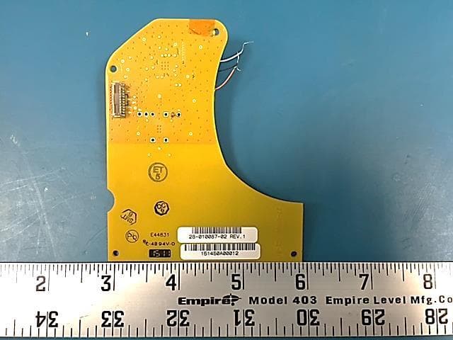
W38-28010087
Oct 01, 2015RFID reader
Equipment Class
DXX - Part 15 Low Power Communication Device Transmitter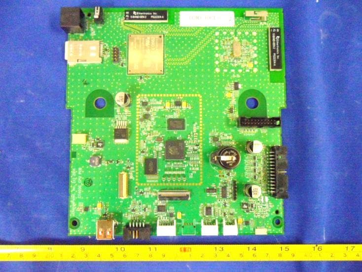
W38-241083G
Nov 02, 2014Communication Board with 802.11 WLAN module
Equipment Class
DTS - Digital Transmission System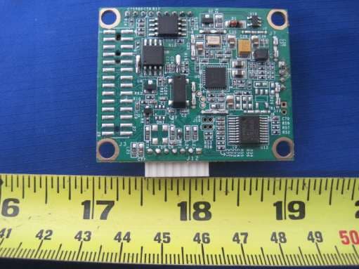
W38-CR1692
Jan 14, 2013Contactless Reader
Equipment Class
DXX - Part 15 Low Power Communication Device Transmitter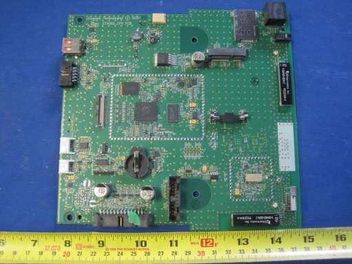
W38-241083Z
Dec 17, 2012ChargePoint Network Communication Board
Equipment Class
DTS - Digital Transmission System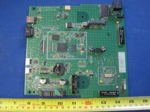
W38-241083
Dec 17, 2012ChargePoint Network Communication Board
Equipment Class
DTS - Digital Transmission System