W39TRKWireless Motion Sensing Security System
LTB Enterprises, LLC dba TrakGard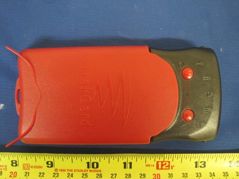
Click to zoom
Application Details
- Equipment Class
- DSC - Part 15 Security/Remote Control Transmitter
- Date of Grant
- Apr 10, 2011
- Application Purpose
- Original Equipment
- Date of Application
- Apr 10, 2011
- Equipment Note
- Wireless Motion Sensing Security System
- Frequency Range
- 433.33000000 - 433.33000000
- Country
- United States
Documents & Files
Document Text
Text extracted from the exhibit documents filed with the FCC. Open a document above to read the original.
Users Manual
LTB Enterprises, LLCver. 20110223X0.01 TRAKGARD TM -PortalAlarmSystem Instruction Manual ModelTRK FCC IDW39TRK Version20110223X0.01 LTB Enterprises, LLC dba TrakGard TM POBox 727 Vancouver, WA 98666 Website:www.Trakgard.com Email support: [email protected] . LTB Enterprises, LLCver. 20110223X0.01 Parts supplied: 1 babysitter unit 1 baby unit 2 UL certified 9 V DC power supply modules 8 AA 1.5 Vnon-rechargeablebatteries TrakGard TM is aportablewirelessmotion sensingalarmsystemdesignedto alert a user of human(or animal)activity occurring in front ofits sensing lens.In its simplest form,it consists of onebabysitter(Portal)deviceandonebaby(Guard)device.In the absence of obstacles,these two devices communicateover distanceswell in excess of1000feet. Evenin the presence of obstacles,the wireless waves ricochet around obstacles over long distances.It is therefore not necessary forthe babysitter and babyto be in line of sight to communicatewith one another. The baby can beplacedinsidesuchplacesasthe interiors of cars and trucks,or aroundfreight or container boxes,hallways, door entrances,insidesmallclosedspacesincludingbackpacks,gym bags,tool boxes, medicine cabinets, safes,or any other area to be monitored for activity. The babysitter-baby combination can also be used in helping alert a caregiver of theambulatory activityofaloved one walking about inthe privacy of their own home or apartment, or in an assisted living facility. It can also be shared by neighbors looking after the homes of their neighbors absentoron vacation from their home, providing a means of alerting a watchful neighbor of an intrusion in time to call for help, and henceservea role in neighborhoodcrime preventionprograms. Security alerts(intrusion events sensed by babies)display on thefront panel of thebabysitter as flashing LEDs and are accompanied by an audiblerepeating beep.The front face panel of each device has a total for five LEDs arrayed across the top edge ofthepanel in an arc. The LED in the middle of the array designated “P” is reserved for the babysitter. The remaining LEDs, two to the left of theP LED designated I and II and two to the right of the P LED designated III and IIII, are reservedfor assignment to babies.Additional babies can be obtained fromTrakGard TM for linking up with a babysitter currently in operation by a user. A plug-in receptacle is located on the side of each device forsupplying power in maintaining operation of the device usingaUL 9V power supply moduleplugged into a standard wall outlet. 1 Devices run off of a set of 4 AA batteries.If rechargeablebatteries are used in the battery holder,periodic use of the power module connected to the device through the plug-in receptaclewill automatically recharge the batteries. 1 The polarity of the barrel plug (5.5 mm OD x 2.1 mm ID x 9.5 mm length) conveying power from a DC power supply module must be positive on the insideand negative on the outside.To work properly when connected to an external power source, babies and babysitters require a power source supply between 7V to14V having a 3 Watt (or better) output. LTB Enterprises, LLCver. 20110223X0.01 Whereas the use of batteries provides portability of the babysitter and babies,babysitters, and babies, whenever practical, should preferably be operated using the 9V power module plugged into a wall outlet with its DC barrel adapter inserted into the power receptacle. Babies, and babysitters,willalso powerup, recharge and operateusing UL certified DC power supply modules designed for powering up electronic devices in a car or truck. Babysitterswill run off ofa single set ofbatteriesover a period ofseveral hoursunplugged from the power supply module.Depending uponhow muchactivity occursin front of babies, theycan operate on battery powerover a period ofseveral months. OperatingInstructions Getting Started–What is ababysitter and babyand how do theywork together? Whendevicesareturned offthey appearidentical. Once they are powered up, however,it will be evident that there are two types of devices working together in establishing an operating surveillance system. The device reporting security alerts to a user isababysitter.Ababy,under itsmanagement,is the second device placed at a site to be surveyed for activity.The babysitter is not limited to managing one baby–additional babies can be managed by a babysitter. When powered up and operating, thebabysitteris recognizable by the presence of a blinking green LED in the “P” position on the front panel of the device. The babysitter is used to assign babies identities in reporting security alerts to it, and the place to look in determining what is going onin front ofbabiesplaced in surveillance positions a user desires to monitor. Is humanor animalactivity occurring, or has it occurred, in front ofababy carrying out surveillance? If so,the babysitter will emit a repeating audible beep, its “P” LED will flash red. The LED assignedto the babyreportingthesecurityalert willalso blink in green. Babiessimply report activity as it occurs intheir field of view. Whenever human or animal movement occurs in proximity to a baby, it instantly senses the activity, awakens and sends asecurity alert to the babysitter,that was used to give it an LED identity (position I, II, III, or IIII). In the absence of activity, the baby drops back into a sleeping state. A baby ordinarily displays no lit LED unless it is awakened, and is easily recognized by the absence of a lit LED after it is powered up andhasdropped into its sleeping state. The first time a baby is brought into service it must be given an LED assignment with a babysitter (e.g., assigned LED position I, II, III or III). Unless a user intends to change the assigned LED position ofababy, oncea babyhasbeen assigneditsLEDposition, it is not necessary to repeat the assignment each time the deviceis turned off and back on. Powering Up Devices Slidethe on/off switch on the back of each device to the right “on” position. …
Text truncated - open the document above for the full version.
Internal Photos
EUT Cover Off View -1 EUT Cover Off View -2 PCBA board Top View PCBA board Bottom View Antenna View
Test Report
LTB ENTERPRISES, LLC PORTAL ALARM SYSTEM Model: TRK March 28th, 2011 Report No.: SL11021801-LTB-001(FCC, IC) (This report supersedes NONE) Modifications made to the product : None This Test Report is Issued Under the Authority of: David Zhang Test Engineer Leslie Bai Engineering Reviewer This test report may be reproduced in full only. Test result presented in this test report is applicable to the representative sample only. a Title: FCC RF Test Report of LTB Enterprises, LLC Model : TRK To 47 CFR 15.203, 15.207, 15.209, 15.231: 2010 ; RSS-Gen Issue 3: 2010, RSS-210 Issue 8 : 2010 Serial# SL11021801-LTB-001(FCC, IC) Issue Date March 28th, 2011 Page 2 of 58 www.siemic.com Laboratory Introduction ATION SIEMIC, headquartered in the heart of Silicon Valley, with superior facilities in US and Asia, is one of the leading independent testing and certification facilities providing customers with one-stop shop services for Compliance Testing and Global Certifications. In addition to testing and certification, SIEMIC provides initial design reviews and compliance management through out a project. Our extensive experience with China , Asia Pacific, North America, European, and international compliance requirements, assures the fastest, most cost effective way to attain regulatory compliance for the global markets . Accreditations for Conformity Assessment Country/Region Accreditation Body Scope USA FCC, A2LA EMC , RF/Wireless , Telecom Canada IC, A2LA, NIST EMC, RF/Wireless , Telecom Taiwan BSMI , NCC , NIST EMC, RF, Telecom , Safety Hong Kong OFTA , NIST RF/Wireless ,Telecom Australia NATA, NIST EMC, RF, Telecom , Safety Korea KCC/RRA, NIST EMI, EMS, RF , Telecom, Safety Japan VCCI, JATE, TELEC, RFT EMI, RF/Wireless, Telecom Mexico NOM, COFETEL, Caniety Safety, EMC , RF/Wireless, Telecom Europe A2LA, NIST EMC, RF, Telecom , Safety Accreditations for Product Certifications Country Accreditation Body Scope USA FCC TCB, NIST EMC , RF , Telecom Canada IC FCB , NIST EMC , RF , Telecom Singapore iDA, NIST EMC , RF , Telecom EU NB EMC & R&TTE Directive a Title: FCC RF Test Report of LTB Enterprises, LLC Model : TRK To 47 CFR 15.203, 15.207, 15.209, 15.231: 2010 ; RSS-Gen Issue 3: 2010, RSS-210 Issue 8 : 2010 Serial# SL11021801-LTB-001(FCC, IC) Issue Date March 28th, 2011 Page 3 of 58 www.siemic.com This page has been left blank intentionally. a Title: FCC RF Test Report of LTB Enterprises, LLC Model : TRK To 47 CFR 15.203, 15.207, 15.209, 15.231: 2010 ; RSS-Gen Issue 3: 2010, RSS-210 Issue 8 : 2010 Serial# SL11021801-LTB-001(FCC, IC) Issue Date March 28th, 2011 Page 4 of 58 www.siemic.com CONTENTS 1 EXECUTIVE SUMMARY & EUT INFORMATION.............................................................................................................. 6 2 TECHNICAL DETAILS.................................................................................................................................................... 7 3 MODIFICATION.............................................................................................................................................................. 8 4 TEST SUMMARY............................................................................................................................................................ 9 5 MEASUREMENTS, EXAMINATION AND DERIVED RESULTS...................................................................................... 10 ANNEX A. TEST INSTRUMENT & METHOD.......................................................................................................................... 21 ANNEX B EUT AND TEST SETUP PHOTOGRAPHS............................................................................................................. 26 ANNEX C. TEST SETUP AND SUPPORTING EQUIPMENT..................................................................................................... 27 ANNEX D USER MANUAL, BLOCK & CIRCUIT DIAGRAM.................................................................................................... 31 ANNEX E SIEMIC ACCREDITATION..................................................................................................................................... 32 a Title: FCC RF Test Report of LTB Enterprises, LLC Model : TRK To 47 CFR 15.203, 15.207, 15.209, 15.231: 2010 ; RSS-Gen Issue 3: 2010, RSS-210 Issue 8 : 2010 Serial# SL11021801-LTB-001(FCC, IC) Issue Date March 28th, 2011 Page 5 of 58 www.siemic.com This page has been left blank intentionally. a Title: FCC RF Test Report of LTB Enterprises, LLC Model : TRK To 47 CFR 15.203, 15.207, 15.209, 15.231: 2010 ; RSS-Gen Issue 3: 2010, RSS-210 Issue 8 : 2010 Serial# SL11021801-LTB-001(FCC, IC) Issue Date March 28th, 2011 Page 6 of 58 www.siemic.com 1 Executive Summary & EUT information The purpose of this test programme was to demonstrate compliance of the LTB Enterprises, LLC Portal Alarm System, against the current Stipulated Standards. The Portal Alarm System have demonstrated compliance with the 47 CFR 15.203, 15.207, 15.209, 15.231: 2010 and RSS-Gen Issue 3: 2010, RSS-210 Issue 8 : 2010. EUT Information EUT Description : Portal Alarm System Model No : TRK Serial No : N/A Input Power : 9 VDC Classification Per Stipulated Test Standard : Low Power Transceiver a Title: FCC RF Test Report of LTB Enterprises, LLC Model : TRK To 47 CFR 15.203, 15.207, 15.209, 15.231: 2010 ; RSS-Gen Issue 3: 2010, RSS-210 Issue 8 : 2010 Serial# SL11021801-LTB-001(FCC, IC) Issue Date March 28th, 2011 Page 7 of 58 www.siemic.com 2 TECHNICAL DETAILS Purpose Compliance testing of Portal Alarm System with stipulated standard Applicant / Client LTB Enterprises, LLC Manufacturer LTB Enterprises, LLC PO Box 727 Vancouver, WA 98666 Laboratory performing the tests SIEMIC Laboratories Test report reference number SL11021801-LTB-001(FCC, IC) Date EUT received March 14th, 2011 Standard applied 47 CFR 15.203, 15.207, 15.209, 15.231: 2010 RSS-Gen Issue 3: 2010, RSS-210 Issue 8 : 2010 Dates of test (from – …
Text truncated - open the document above for the full version.
Test Setup Photos
Radiated Emission Front View (< 1Ghz) Radiated Emission Rear View (< 1Ghz) Radiated Emission Front View(>1GHz) Radiated Emission Rear View(>1GHz) Conducted Emission Front View Conducted Emission Rear View
Contact Information
Applicant
Terrence Green(President)
Test Firm
Bureau Veritas Consumer Products Services, Inc.Sarb Shelopal
[email protected]+1 925 963 4420
Technical Specifications
| # | Rule Parts | Frequency Range | Power Output |
|---|---|---|---|
| 1 | 15.231 | 433.33 MHz - 433.33 MHz | - |