W6U150V450URDU MODULE(VHF/UHF)
SOLiD, Inc.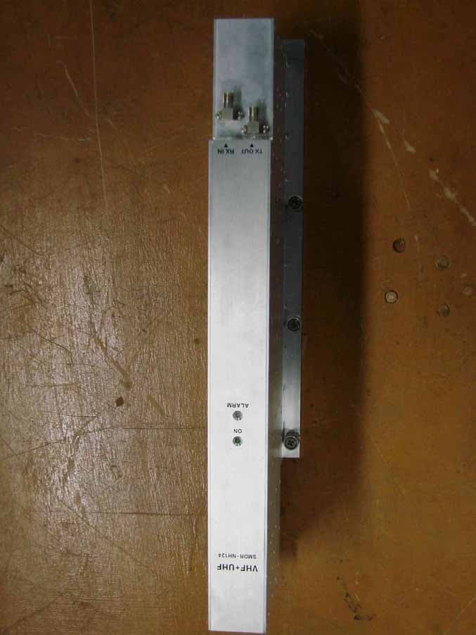
Click to zoom
Application Details
- Equipment Class
- TNB - Licensed Non-Broadcast Station Transmitter
- Date of Grant
- Dec 28, 2009
- Application Purpose
- Original Equipment
- Date of Application
- Dec 13, 2009
- Equipment Note
- RDU MODULE(VHF/UHF)
- Frequency Range
- 450.00000000 - 512.00000000
- Company
- SOLiD, Inc.
- Country
- South Korea
Documents & Files
Document Text
Text extracted from the exhibit documents filed with the FCC. Open a document above to read the original.
Users Manual
Confidential & Proprietary 1/99 SMDR-NH124 Installation and Operation Manual Document Reference: Version: V1.0 Document Status: Release 1 Issue Date: Jan. 02, 2009 Author: Kyung Eun Han Department: R&D Division Team 1 Authorizing Manager: Youngshin Yeo Confidential & Proprietary 2/99 REVISION HISTORY Version Issue Date No. of Pages InitialsDetails of Revision Changes V 1.0 Jan. 02, 2009 Original V 2.0 Oct. 23. 2009 Additional RDU(VHF+UHF) Technical Support SOLiD serial numbers must be available to authorize technical support and/or to establish a return authorization for defective units. The serial numbers are located on the back of the unit, as well as on the box in which they were delivered. Additional support information may be obtained by accessing the SOLiD Tehcnology, Inc. website at www.st.co.kr or send email at [email protected] This manual is produced by Global Business Division Business Team 1. Printed in Korea. Confidential & Proprietary 3/99 Contents Section1 ͑ Safety & Certification Notice................................................................... 8 ͑ Section2 ͑ System Overview ................................................................................... 10 ͑ 2.1 ͑ General overview......................................................................................... 11 ͑ 2.2 ͑ System overview.......................................................................................... 12 ͑ Section3 ͑ System Specifications........................................................................... 14 ͑ 3.1 ͑ System specifications................................................................................. 15 ͑ 3.1.1 ͑ Physical Specifications......................................................................... 15 ͑ 3.1.2 ͑ Optic wavelength and Laser power...................................................... 16 ͑ 3.1.3 ͑ Environmental specifications............................................................... 16 ͑ 3.1.4 ͑ Operating Frequencies range............................................................... 16 ͑ 3.1.5 ͑ Specifications Per band........................................................................ 17 ͑ Section4 ͑ System Configuration and Functions .................................................. 22 ͑ 4.1 ͑ BIU (BTS Interface Unit).............................................................................. 22 ͑ 4.1.1 ͑ Specifications of BIU............................................................................. 22 ͑ 4.1.2 ͑ Block diagram of BIU............................................................................. 23 ͑ 4.1.3 ͑ BIU parts................................................................................................. 23 ͑ 4.1.4 ͑ Function by unit..................................................................................... 24 ͑ 4.1.5 ͑ Front/rear panels of BIU........................................................................ 28 ͑ 4.2 ͑ ODU (Optic distribution Unit)...................................................................... 30 ͑ 4.2.1 ͑ Specifications of ODU........................................................................... 31 ͑ 4.2.2 ͑ Block Diagram of ODU.......................................................................... 31 ͑ 4.2.3 ͑ ODU parts............................................................................................... 32 ͑ 4.2.4 ͑ Function by unit..................................................................................... 33 ͑ 4.2.5 ͑ Front/rear panels of MHU...................................................................... 34 ͑ 4.2.6 ͑ Interface with BIU.................................................................................. 35 ͑ 4.3 ͑ OEU (Optic Expansion Unit)........................................................................ 36 ͑ 4.3.1 ͑ Specifications of OEU........................................................................... 37 ͑ 4.3.2 ͑ Block Diagram of OEU........................................................................... 37 ͑ 4.3.3 ͑ OEU parts............................................................................................... 37 ͑ 4.3.4 ͑ Function by unit..................................................................................... 38 ͑ 4.3.5 ͑ Front/rear panels of OEU...................................................................... 42 ͑ 4.4͑ROU (Remote Optic Unit)............................................................................ 43͑ Confidential & Proprietary 4/99 4.4.1 ͑ Specifications of ROU........................................................................... 43 ͑ 4.4.2 ͑ Block Diagram of ROU.......................................................................... 44 ͑ 4.4.3 ͑ ROU parts............................................................................................... 44 ͑ 4.4.4 ͑ Function by unit..................................................................................... 46 ͑ 4.4.5 ͑ Bottom of ROU....................................................................................... 50 ͑ Section5 ͑ System Installation & Operation........................................................... 52 ͑ 5.1 ͑ BIU Installation............................................................................................. 53 ͑ 5.1.1 ͑ BIU Shelf Installation............................................................................. 53 ͑ 5.1.2 ͑ BIU Power Cabling................................................................................. 54 ͑ 5.1.3 ͑ RF Interface at BIU................................................................................. 55 ͑ 5.1.4 ͑ MDBU insertion...................................................................................... 59 ͑ 5.1.5 ͑ ODU Interface......................................................................................... 60 ͑ 5.1.6 ͑ Consumption Power of BIU.....................................…
Text truncated - open the document above for the full version.
Users Manual
Confidential & Proprietary 33/99 4.2.3ODU parts Figure 4.10 – ODU Inner Look No.UnitDescription Remark 1 DOU DOU Convert TX RF signals into optical signals; Convert RX optical signals into RF signals; Provide up to four optical ports per DOU Max 2ea 2 2W 2Way Divider Divide TX RF signals into two; Combine two RX RF signals into one 3 DU Distribution Unit Distribute power and signals to DOU 4 Shelf 19” rack, 1U 5 Accessories 15PIN DSUB, Male to female 1pcs RF Coaxial Cable Assembly 2pcs Confidential & Proprietary 34/99 4.2.4Function by unit 1) Donor Optic Unit (DOU) DOU makes electronic-optical conversion of TX signals and makes optical-electronic conversion of RX signals. With an optic splitter in it, this unit divides optical signals from Laser Diode into four and then distributes them to each optical port. With a total of four Photo Diodes in RX, DOU makes optical-electronic conversion of signals received from each optical port. In addition, the unit is equipped with ATT for optical compensation made in case of optical cable loss. With internal WDM, it uses only one optical cable to be connected with ROU. Figure 4.11 – MDBU Outer Look 2) 2Way Divider (2W) 2W is equipped with two 2-way splitters in a one-module form and the splitters work for TX/RX signals, respectively. Designed in broadband type, the divider combines and divides 2GHz or higher of signals from FSK modem signals. Figure 4.12 – 2Way Divider Outer Look Confidential & Proprietary 35/99 4.2.5Front/rear panels of MHU 1) Front panel Figure 4.13 – BIU front panel Outer Look ItemDescription 1,2 LED indicator to check DOU module state to see if it is abnormal 2) Rear panel Figure 4.14 – Rear panel Outer Look ItemDescription 1. Optic Port SC/APC optical connector terminal; use one optical cable per ROU. 2. DC I/O Port Terminal to deliver power and state values 3. RX RF Port RX RF signal interface terminal 4. TX RF Port TX RF signal interface terminal Confidential & Proprietary 36/99 4.2.6Interface with BIU Figure 4.15 – Interface between MHU and ODU On the top of BIU, up to four ODUs can be stacked. In this case, it is recommended to stack the units at least 1U of an interval between BIU, for heat from BIU may climb up to ODU, which may cause flame. As seen in the figure below, connect the coaxial cable for TX and another coaxial cable for RX with corresponding ports at the rear of BIU. For power supply and communication, connect 15Pin D-Sub Connector cable with a corresponding port. Confidential & Proprietary 37/99 4.3 OEU (Optic Expansion Unit) OEU is mainly used to remotely deliver signals for Campus clusters. At the upper part, this unit combines with ODU and receives TX optical signals to convert them into RF signals. Then, it regenerates the signals to secure S/N feature and converts them into optical signals. The signals are sent to ROU through optical cables. When it receives RX optical signals from ROU, the unit converts them into RF signals to regenerate the signals and then converts them into optical signals to send them to ODU. In OEU, one shelf can be equipped with up to two DOUs. The DOU is the same as the module used for ODU. Up to two OEUs can be connected with ODU. Figure 4.16 – OEU Outer Look Confidential & Proprietary 38/99 4.3.1Specifications of OEU ItemSpec. Remark Size 482.6(19”) x 88.1(2U) x 450 mm Weight 9.3 Kg Power consumption 48 W Full Load 4.3.2Block Diagram of OEU 4.3.3OEU parts Confidential & Proprietary 39/99 Figure 4.17 – OEU Inner Look No.UnitDescription Remark 1 DOU Donor Optic Unit Convert TX RF signals into optical signals; Convert RX optical signals into RF signals; Provide up to four optical ports per DOU Max 2ea 2 EWDM Expansion Wavelength Division Multiplexer Convert TX optical signals into RF signals; Convert RX RF signals into optical signals; Compensate for optical cable loss with ODU 3 ECPU Expansion Central Processor Unit Control and monitoring system status Control and monitoring with RS232 Relay state values of ROU to BIU 4 EPSU Expansion Power Supply Unit Input power: DC -48V, Output power: 9V, 6V 5 ERFM Expansion Radio Frequency Module Regenerate TX signals and transmit FSK modem signals; Regenerate RX signals and receive FSK modem signals 6 Shelf 19” rack, 2U 4.3.4Function by unit 1) Donor Optic Unit (DOU) DOU is the same as the module used for ODU. Confidential & Proprietary 40/99 Figure 4.18 – MDBU Outer Look 2) Expansion Wavelength Division Multiplexer(EWDM) EWDM module makes optical-electronic conversion of TX signals and makes electronic-optical conversion of RX signals. With an FSK modem in it, this multiplexer communicates with BIU. It also has ATT for optical compensation to compensate for optical cable loss between ODUs. Furthermore, it has internal WDM, and so, it needs only one optical cable to work with ROU. Figure 4.19 – EWDM Outer Look 3) Expansion Central Processor Unit(ECPU) ECPU can inquire and control state of modules to be installed into OEU. This unit communicates with upper BIU while communicating with lower ROU. It also acts as communication bridge between BIU and ROU. In addition, the unit has RS-232C port for serial communication, which enables inquiry and control of devices thorugh PC. At the front panel, communication LED indicator indicates Confidential & Proprietary 41/99 communication state with upper BIU and lower ROU. It also has ALM LED indicator to show if a device gets faulty. Figure 4.20 – ECPU Outer Look 4) Expansion Radio Frequency Module(ERFM) ERFM reconstructs Signal to Noise degraded by optical modules. With an internal FSK modem, this module communicates with ROU. Figure 4.21 – ERFM Outer Look 5) Expansion Power Supply Unit(EPSU) As DC/DC Converter, EPSU receives -48V of input and provides +9V and +6V of DC power required for OEU. Confidential & Proprietary 42/99 Figure 4.22 – ERFM Outer Look
Users Manual
Confidential & Proprietary 43/99 4.3.5Front/rear panels of OEU 1) Front panel Figure 4.23 – OEU front panel Outer Look ItemDescription 1.EWDM LED LED indicator to check EWDM state to see if it is abnormal 2.DOU LED LED indicator to check DOU module state to see if it is abnormal 3.System LED and Reset Communication state with devices, alarm status of the system and reset switch 4. NMS(RS-232C port) RS-232C port for communication and diagnosis of devices through PC/laptop. This equipment is indoor use and all the communication wirings are limited to inside of the building 2) Rear panel Figure 4.24 – Rear panel Outer Look ItemDescription 1. GND Port Terminal for system ground 2. DC Input Port Input terminal for DC -48V 3.power switch Power ON/OFF switch 4. To/From ODU Optic Port SC/APC optical connector terminal 5. To/From ROU Optic Port SC/APC optical connector terminal; use one optical cable per ROU. Confidential & Proprietary 44/99 4.4 ROU (Remote Optic Unit) ROU receives TX optical signals from ODU or OEU and converts them into RF signals. The converted RF signals are amplified through High Power Amp in a corresponding RDU, combined with Multiplexer module and then radiated to the antenna port. When receiving RX signals through the antenna port, this unit filters out-of-band signals in a corresponding RDU and sends the results to Remote Optic Module to make electronic-optical conversion of them. After converted, the signals are sent to a upper device of ODU or OEU. ROU can be equipped with up to three RDUs (Remote Drive Unit) and the module is composed of maximal Dual Band. Figure 4.25 – ROU Outer Look ROU is designed in a cabinet, and provides the following functions and features. 4.4.1Specifications of ROU ItemSpec. Remark Size(mm) 482.6(19“) x 258 x560, Including Bracket Weight 35.45 Kg Power consumption 265 W Full Load Confidential & Proprietary 45/99 4.4.2Block Diagram of ROU 4.4.3ROU parts Figure 4.26 – ROU Inner Look Confidential & Proprietary 46/99 No.UnitDescription Remark 1 RDU+BPF Remote Drive Unit Filter and high amplify TX signals; Filter and amplify RX signals; Remove other signals through BPF BPF is exclude from VHF+UHF module 2 RPSU Remote Power Supply Unit Input power: DC -48V, Output power: 27V,9V, 6V For 120V input of AC/DC; For -48V input of DC/DC 3 R-OPTIC Remote Optic Make RF conversion of TX optical signals; Convert RX RF signals into optical signals; Compensates optical loss Communicates with BIU/OEU though the FSK modem 4 RCPU Remote Central Processor Unit Controls signal of each unit Monitors BIU/ODU/OEU status through FSK modem communication 5 Multiplexer Multiplexer Combine TX signals from 3 RDUs; Distribute RX signals to 3 RDUs; Enable you to use a single antenna port 6 Enclosure Enclosure to satisfy NEMA4; Enable Wall/Rack Mount; Check if the system is normal, through the front panel LED 7 SIU System Interface Unit Distribute power and signals of each module Confidential & Proprietary 47/99 4.4.4Function by unit 1) Remote Drive Unit (RDU) When receiving TX signals from each band through Remote Optic, RDU filters the signals and amplifies them with High Power Ampifier. The unit also filters RX signals given through Multiplexer and amplifies them to send the signals to Remote Optic. In the unit, there is ATT to adjust gain. RDU devices are varied for each frequency band, including the following: BPF NoUnit naming Description TXRX 1 RDU 800PS Single, External BPF Internal BPF 2 RDU 850C Single, External BPF External BPF 3 RDU 1900P+AWS-1 Dual, External BPF(1900P) Internal BPF(AWS-1) External BPF(1900P) Internal BPF(AWS-1) 4 RDU 800PS+900I+PA Dual, External BPF(800PS) Internal BPF(900I+PA) Internal BPF(800PS) External BPF(900I+PA) 5 RDU 850C+700PS Dual, External BPF(850C) Internal BPF(700PS) External BPF(850C) Internal BPF(700PS) 6 RDU VHF+UHF Dual External BPF(VHF,UHF) External BPF(VHF,UHF) 800PS800PS+900I+PA Confidential & Proprietary 48/99 Figure 4.27 – RDU Outer Look 2) Remote Power Supply Unit (RPSU) RPSU receives -48V of input. This unit is divided into DC/DC type to output +6V, +9V and +27V of DC power and AC/DC type to receive 120V of AC input and to output +6V, +9V and +27V of DC power. Upon order, either of the two types should be decided. MS Connector, which uses ports to receive inputs, is designed to accept any of AC and DC. Only in this case, the input cable is different. RPSU has a circuit brake to turn the power ON/OFF and has LED indicator at the top to check if input power is normally supplied. 850C 850C+700PS 1900P+AWS-1 VHF+UHF Confidential & Proprietary 49/99 3) Remote Optic(R OPTIC) Remote Optic converts optical signals into RF signals and performs vice versa. With an FSK modem in it, the unit communicates with upper devices. It also has internal ATT for optical compensation to compensate for optical cable loss, if any. Figure 4.28 – R OPTIC Outer Look 4) Remote Central Processor Unit (RCPU) RCPU can monitor and control each module of ROU. This unit receives and analyzes upper communication data from Remote Optic and reports the unit's own value to upper devices. At the front of the module, it has LED indicator to show system status, letting you check any abnormalities at a time. At the same front, it also has communication LED Indicators to show communication status with upper devices. Through RS-232C Serial Port, the unit enables you to Confidential & Proprietary 50/99 check and control device status through PC and laptop. This equipment is indoor use and all the communication wirings are limited to inside of the building. Figure 4.29 – RCPU Outer Look 5) Multiplexer Multiplexer works as a module to combine or distribute multiple signals into one antenna. This device has a port to combine multiple signals. You need to connect input and output ports of RDU through a corresponding port. Figure 4.30 – Multiplexer Outer Look Confidential & Proprietary 51/99 6) System Interface Unit(SIU) SIU distributes power and signals to each module. 4.4.…
Text truncated - open the document above for the full version.
Users Manual
Confidential & Proprietary 63/99 If ODU is not connected in the right order, related devices may fail to communicate with each other or the unit may read wrong information. Given this, you need to connect the unit with accurate RF Port and Signal Port in a corresponding number. For unused RF Ports for ODU expansion, make sure to terminate them using SMA Term. When you put ODU on the top of BIU, it is recommended to install the unit at least 1U apart from BIU. Heat from BIU climbes up to reach ODU. 5.1.6 Consumption Power of BIU The table below shows power consumption of BIU: PartUnitConsumption PowerRemark Shelf MCDU MCPU Common Part MPSU 7.5 W MDBU 800PS 12W MDBU 800PS+900I+Paging 20W MDBU 850C 12W MDBU 850C+700PS 19W MDBU 1900P 20W MDBU MDBU AWS-1 12W BIU supplies power for ODU. Therefore, when you want to calculate total power consumption of BIU, you need to add power consumption of ODU to the total value. Power consumption of ODU is given in the later paragraph describing ODU. Confidential & Proprietary 64/99 5.2 ODU Installation ODU should be, in any case, put on the top of BIU. This unit gets required power and RF signals from BIU. The following table shows components of ODU: No.UnitDescription Remark Shelf Including Main Board, 19”,1U 1EA RF Cable SMA(F) to SMA(F), 400mm 2EA Common Part Signal Cable 2Row(15P_F) to 2Row(15P_M),650mm 1EA Optional Part DOU Optical Module with 4 Optic Port Up to 2EA to be inserted 5.2.1 ODU Shelf Installation ODU is a shelf in around 1U size. Its width is 19” and so this unit should be inserted into a 19” Standard Rack. ODU should be, in any case, put on the top of BIU. BIU should be distant around 1U when the unit is installed. 5.2.2 ODU Power Cabling ODU does not operate independently. The unit should get power from BIU. When you connect 2-column, 15-pin D-SUB Signal cable from BIU and install DOU, LED on the front panel is lit. Through this LED, you can check state values of LD and PD of DOU. 5.2.3 ODU Optic Cabling As optical module shelf, ODU makes electronic-optical conversion of TX signals and then makes optical-electronic conversion of RX signals. ODU can be equipped with up to two DOUs. One DOU supports four optical ports and one optical port can be connected with ROU. Optionally, only optical port 4 can be connected with OEU. As WDM is installed in DOU, the unit can concurrently send and receive two pieces of wavelength (TX:1310nm, RX:1550nm) through one optical core. DOU has SC/APC of optical adaptor type. Confidential & Proprietary 65/99 Figure 5.4 – Optical cable of SC/ACP Type For optical adaptor, SC/APC type should be used. To prevent the optical access part from being marred with dirt, it should be covered with a cap during move. When devices are connected through optical cables, you need to clear them using alcohocol to remove dirt. 5.2.4 Insert DOU to ODU In an ODU Shelf, up to two DOUs can be installed. DOU module is in Plug in Play type. When you insert DOU in ODU, insert the unit into the left DOU1 slot first. You can be careful as the number is silk printed at the left. The following figure shows installation diagram of ODU with one DOU inserted in it. The following figure shows installation diagram of ODU with two DOUs inserted in it. When you insert DOU into ODU, insert the unit into the left DOU1 slot first. Into unused slot, you need to insert BLANK UNIT in any case. Confidential & Proprietary 66/99 5.2.5 Consumption Power of ODU ODU gets power from BIU. One ODU can be equipped with up to two DOUs. Depending on how many DOUs are installed, power consumption varies. The table below shows power consumption of ODU: PartUnitConsumption PowerRemark ODU_4 DOU 1 EA 13W ODU_8 DOU 2 EA 26W 5.3 ROU Installation 5.3.1 ROU Enclosure installation ROU is designed to be water- and dirt-proof. The unit has the structure of One-Body enclosure. It satisfies water-proof and quake-proof standards equivalent of NEMA4. ROU can be mounted into either of a 19” Standard Rack or on a Wall. Basically, ROU has both of a Wall Mount Bracket and a Rack Mount Bracket. Depending on the use of the Rack Mount Bracket, the bracket can be removed. The following shows dimension of the fixing point for the Wall Mount Bracket. Figure 5.5 – How to install ROU Confidential & Proprietary 67/99 Figure 5.6 – Dimension used to install ROU on the WALL ROU Wall Mount Installation Turn M12 Fixing Screws by half on the wall and fully fix the screw with a Wall Mount Bracket on it. For convenience, the Wall Mount Bracket has fixing holes to let you easily mount an enclosure. Turn the M5 Wrench Bolt by half at each side of the Heatsink of the enclosure. Confidential & Proprietary 68/99 Put the enclosure with the M5 Wrench Bolt fixed on the fixing groove and fix the M5 Wrench Bolts into the remaining fixing holes. In this case, you will use 12 M5 Wrench Bolts in total except bolts used for the fixing groove. ROU Rack Mount Installation Like other units, ROU is designed to be inserted into a rack. The unit occupies around 13U of space except cable connection. Confidential & Proprietary 69/99 ROU component ROU has the following components: No.UnitDescription Remark Enclosure Including Rack & Wall cradle 1EA RCPU - 1EA R_OPTIC With SC/ACP adaptor1EA RPSU Alternative DC-48V or AC 120V 1EA Multi-Plexer - 1EA Common Part Power Cable - MS Connector with 3 hole to AC 120 plug(AC) - MS Connector with 2 lug termination(DC) Optional Part RDU+BPF 800PS,800PS+900I+Paging,850C,850C+700PS, 1900P+ AWS-1 RDU, VHF+UHF(NO BPF) Up to 3EA to be inserted Basically, the common part of ROU should have an enclosure and it is equipped with RCPU to inquire and control state of each module, R_OPTIC to make both of electronic-optical and optical-electronic conversions, RPSU to supply power for ROU and a Multi-Plexer to help share multiple TX/RX signals through one antenna. It should have Power Cable for external rectifier or to supply required power. Confidential & Proprietary 70/99 In addition, RDU can be …
Text truncated - open the document above for the full version.
Users Manual
Confidential & Proprietary 78/99 Connect BPF 1900P port with 1900P port of 1900P RDU through ྚ1900P+AWS-1 RF- 01 RF CABLE . Insert the combined ྛ 1900P+AWS-1 BPF Ass’y into any slot of ROU. Combination point of ྜ 1900P+AWS-1 BPF Ass’y of the multiplexer Interface Point Multiplexer Port naming 1900P+AWS-1 RDU 1900P BPF Remark AWS-1+1900P COM 1900P+AWS - How to install RDU VHF+UHF Ass’y The following components are required: No.UnitDescription Remark 1 RDU VHF+UHF RF Module 2 RDU VHF+UHF RF CABLE SMA(M) to SMA(M), 460mm 3 RDU VHF+UHF RF CABLE SMA(M) to SMA(M), 380mm Insert the combined ྙVHF+UHF RDU into any slot of ROU. ྚ Connect RDU VHF+UHF Port with ROU VHF+UHF Port through VHF+UHF RF CABLE Confidential & Proprietary 79/99 You cannot insert the same module and band into MULTIPLEXER port at the same time. For example, you are not supposed to insert both of 800PS RDU and 800PS+900I+PA RDU into ROU at the same time. In the same way, you cannot concurrently insert both of 850C RDU and 850C+700PS RDU into ROU. Information of LED at the front RDU RDU has the structure of enabling a random RDU to be inserted into three slots. ROU can be equipped with a total of three RDUs. If only one RDU is inserted into a slot and the other slots ramian reserved, you need to insert BLANK cards into the other slots. When RDU is inserted into ROU, LED of the front panel shows the following information: LEDDescription Power is not supplied ON Power is supplied. Normal Operation ALM Abnormal Operation Confidential & Proprietary 80/99 Up to three RDUs can be inserted. If one or two units are used, then you need to terminate the unused slot of RDU with a BLANK card. 5.3.5 Consumption of RDU The following table shows power consumption of RDU: PartUnitConsumption Power Remark Enclosure RCPU ROPTIC RPSU Common Part Multiplexer 17W RDU 800PS 39W 800PS 49W 900I+PA HPA OFF 900I+PA72W 800PS HPA OFF RDU 800PS+900I+Paging FULL 79W Both HPA ON RDU 850C 39W 850C 49W 700PS HPA OFF 700PS 58W 850C HPA OFF RDU 850C+700PS FULL 93W Both HPA ON 1900P 46W AWS-1 HPA OFF AWS-1 46W 1900P HPA OFF RDU 1900P+AWS-1 FULL 68W Both HPA ON VHF 47W VHF HPA OFF UHF 47W UHF HPA OFF RDU RDU VHF+UHF FULL 74W Both HPA ON Confidential & Proprietary 81/99 For power consumption of ROU, the common part consumes 17W. Depending on the quantity of each RDU, you can add overall power consumption of ROU. Only, in case of Dual-Band signals, power consumption is calculated respectively when HPA of the other party is turned OFF and two HPA devices are turned ON. Note that when you calculate Power Budget. 5.4 OEU Installation OEU is used to expand ROU in Campus Site. OEU is located at a Remote Closet. As it can be equipped with up to two DOUs , you can expand a total of eight ROUs. 5.4.1 OEU Shelf installation OEU is a shelf in around 2U size. Its width is 19” and so this unit should be inserted into a 19” Standard Rack. OEU is in a Remote Closet, providing optical ports of ROU. The following table shows power consumption of OEU: No.UnitDescription Remark Shelf Including EWDM,ERF,EPSU,ECPU, 19”,2U 1EA Common Part Power Cable -48Vdc Input with two lug terminal 1EA Optional Part DOU Optical Module with 4 Optic Port Up to 2EA to be inserted 5.4.2 OEU Power Cabling The input power of OEU is DC -48V. You need to connect DC cable with the Terminal Block seen at the rear of OEU. Terminal Color of cable Description Remark -48V Blue color Input range: -42 ~ -56Vdc NC Not Connected GND Black color Before connecting the power terminal, you need to connect "+" terminal of Multi Voltage Meter probe with the GND terminal and then connect "–" terminal with -48V to see if “-48Vdc” voltage is measured. After the check, connect the power terminal through the terminal seen below. Confidential & Proprietary 82/99 Note that OEU does not operate if the "+" terminal and the "–" terminal of the -48V power are not inserted into the accurate polarity. 5.4.3 OEU Optic Cabling OEU is connected with upper ODU. With DOU inserted in it, the unit is connected with ROU. Confidential & Proprietary 83/99 As OEU has a shelf with EWDM in it, the unit makes electronic-optical conversion of TX signals from ODU and makes optical-electronic conversion of RX signals. In addition, OEU can be equipped with up to two DOUs. One DOU supports four optical ports and one optical port can be connected with ROU. With WDM in DOU, the unit can concurrently send/receive two pieces of wavelength (TX:1310nm, RX:1550nm) through one optical core. DOU has SC/APC of optical adaptor type. Figure 5.7 – Optical cable of SC/ACP Type For optical adaptor, SC/APC type should be used. To prevent the optical access part from being marred with dirt, it should be covered with a cap during move. When devices are connected through optical cables, you need to clear them using alcohocol to remove dirt. 5.4.4 Insert DOU to OEU Into OEU Shelf, up to two DOUs can be inserted. DOU module is in Plug in Play type. When you insert DOU in OEU, insert the unit into the top DOU1 slot first. You can be careful as the number is silk printed at the left. The following figure shows installation diagram of OEU with one DOU inserted in it. The following figure shows installation diagram of OEU with two DOUs inserted in it. Confidential & Proprietary 84/99 When you insert DOU into OEU, insert the unit into the top DOU1 first. For unused slots, you nedd to install BLANK UNIT into them. 5.4.5 Consumption Power of OEU OEU has -48V DC Power supply in it. ODU can be equipped with up to two DOUs. Depending on the quantity of DOU, power consumption is varied. The following table shows power consumption of OEU: PartUnitConsumption PowerRemark Shelf EWDM ERF Common Part EPSU 12W OEU_4 DOU 1 EA 23W OEU_8 DOU 2 EA 33W 5.5 System Operation and Alarm Status This section describes operation of SMDR-NH124. It deals with procedures and operations for normal system operation after installation. It also describes operations per unit and interworking methods. Confidential …
Text truncated - open the document above for the full version.
Cover Letter(s)
━━━━━━━━━━━━━━━━━━━━━━━━━━━━━━━━━━━━━━━ Date: November 18, 2009 FCC Laboratory 7435 Oakland Mills Road Columbia, MD 21046 Attention : Application Exami…
Text truncated - open the document above for the full version.
Contact Information
Applicant
Yong Chul Kim(Team Manager)
Test Firm
ONETECH Corp.Gea-Won Lee
Technical Specifications
| # | Rule Parts | Frequency Range | Power Output | Emission | Tolerance |
|---|---|---|---|---|---|
| 8 | 9 | 450 MHz - 512 MHz | 251.00 mW | F3E | Amp |
Other Applications from SOLiD, Inc.
May 21, 2026
Equipment Class
B9B - Part 90 Class B Industrial Booster (non-SMR)W6UNMRFM25
Mar 17, 2026nGENESIS
Equipment Class
B2I - Part 20 Industrial Booster (CMRS)W6UNMRFM34
Mar 17, 2026nGENESIS
Equipment Class
B2I - Part 20 Industrial Booster (CMRS)W6UNHRFM34
Mar 17, 2026nGENESIS
Equipment Class
B2I - Part 20 Industrial Booster (CMRS)W6UNMRFM40
Mar 17, 2026nGENESIS
Equipment Class
B2I - Part 20 Industrial Booster (CMRS)