W6U850C700LTECRDU MODULE(850C/700LTEC)
SOLiD, Inc.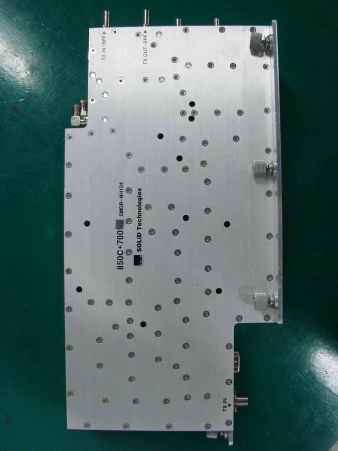
Click to zoom
Application Details
- Equipment Class
- AMP - Amplifier
- Date of Grant
- Aug 29, 2010
- Application Purpose
- Original Equipment
- Date of Application
- Aug 29, 2010
- Equipment Note
- RDU MODULE(850C/700LTEC)
- Frequency Range
- 746.00000000 - 756.00000000
- Company
- SOLiD, Inc.
- Country
- South Korea
Documents & Files
Document Text
Text extracted from the exhibit documents filed with the FCC. Open a document above to read the original.
Users Manual
Confidential & Proprietary 1/139 SMDR-NH124 Installation and Operation Manual Document Reference: Version: V3.0 Document Status: Release 1 Issue Date: Jan. 02, 2009 Author: Kyung Eun Han Department: R&D Division Team 1 Authorizing Manager: Youngshin Yeo Confidential & Proprietary 2/139 REVISION HISTORY Version Issue Date No. of Pages Initials Details of Revision Changes V 1.0 Jan. 02, 2009 Original V 2.0 Oct. 23. 2009 Add RDU(VHF+UHF) V 3.0 Feb. 04. 2010 Add ADD ON V/UHF ROU Technical Support SOLiD serial numbers must be available to authorize technical support and/or to establish a return authorization for defective units. The serial numbers are located on the back of the unit, as well as on the box in which they were delivered. Additional support information may be obtained by accessing the SOLiD Tehcnology, Inc. website at www.st.co.kr or send email at [email protected] This manual is produced by Global Business Division Business Team 1. Printed in Korea. Confidential & Proprietary 3/139 Contents Section1 Safety & Certification Notice................................................................... 9 Section2 System Overview ................................................................................... 11 2.1 General overview......................................................................................... 12 2.2 System overview.......................................................................................... 13 Section3 System Specifications........................................................................... 15 3.1 System specifications................................................................................. 16 3.1.1 Physical Specifications......................................................................... 16 3.1.2 Optic wavelength and Laser power...................................................... 17 3.1.3 Environmental specifications............................................................... 17 3.1.4 Operating Frequencies range............................................................... 17 3.1.5 Specifications Per band........................................................................ 18 Section4 System Configuration and Functions .................................................. 23 4.1 BIU (BTS Interface Unit).............................................................................. 24 4.1.1 Specifications of BIU............................................................................. 24 4.1.2 Block diagram of BIU............................................................................. 25 4.1.3 BIU parts................................................................................................. 25 4.1.4 Function by unit..................................................................................... 26 4.1.5 Front/rear panels of BIU........................................................................ 31 4.2 ODU (Optic distribution Unit)...................................................................... 33 4.2.1 Specifications of ODU........................................................................... 34 4.2.2 Block Diagram of ODU.......................................................................... 34 4.2.3 ODU parts............................................................................................... 35 4.2.4 Function by unit..................................................................................... 36 4.2.5 Front/rear panels of ODU...................................................................... 37 4.2.6 Interface with BIU.................................................................................. 38 4.3 OEU (Optic Expansion Unit)........................................................................ 39 4.3.1 Specifications of OEU........................................................................... 40 4.3.2 Block Diagram of OEU........................................................................... 40 4.3.3 OEU parts............................................................................................... 40 4.3.4 Function by unit..................................................................................... 41 4.3.5 Front/rear panels of OEU...................................................................... 45 4.4 ROU (Remote Optic Unit)............................................................................ 46 Confidential & Proprietary 4/139 4.4.1 Specifications of ROU........................................................................... 46 4.4.2 Block Diagram of ROU.......................................................................... 47 4.4.3 ROU parts............................................................................................... 47 4.4.4 Function by unit..................................................................................... 49 4.4.5 Bottom of ROU....................................................................................... 54 4.5 Add on V/UHF ROU...................................................................................... 56 4.5.1 Specifications of AOR........................................................................... 56 4.5.2 Block Diagram of AOR.......................................................................... 57 4.5.3 AOR parts............................................................................................... 57 4.5.4 Function by unit..................................................................................... 58 4.5.5 Rear of AOR............................................................................................ 59 Section5 System Installation & Operation........................................................... 62 5.1 BIU Installation............................................................................................. 63 5.1.1 BIU Shelf Installation..................................................................…
Text truncated - open the document above for the full version.
Users Manual
Confidential & Proprietary 46/139 4.4 ROU (Remote Optic Unit) ROU receives TX optical signals from ODU or OEU and converts them into RF signals. The converted RF signals are amplified through High Power Amp in a corresponding RDU, combined with Multiplexer module and then radiated to the antenna port. When receiving RX signals through the antenna port, this unit filters out-of-band signals in a corresponding RDU and sends the results to Remote Optic Module to make electronic-optical conversion of them. After converted, the signals are sent to a upper device of ODU or OEU. ROU can be equipped with up to three RDUs (Remote Drive Unit) and the module is composed of maximal Dual Band. Figure 4.25 – ROU Outer Look ROU is designed in a cabinet, and provides the following functions and features. 4.4.1 Specifications of ROU Item Spec. Remark Size(mm) 482.6(19“) x 258 x560, Including Bracket Weight 35.45 Kg Power consumption 265 W Full Load Confidential & Proprietary 47/139 4.4.2 Block Diagram of ROU 4.4.3 ROU parts Figure 4.26 – ROU Inner Look No. Unit Description Remark Confidential & Proprietary 48/139 1 RDU+BPF Remote Drive Unit Filter and high amplify TX signals; Filter and amplify RX signals; Remove other signals through BPF BPF is exclude from VHF+UHF module 2 RPSU Remote Power Supply Unit Input power: DC -48V, Output power: 27V,9V, 6V For 120V input of AC/DC; For -48V input of DC/DC 3 R-OPTIC Remote Optic Make RF conversion of TX optical signals; Convert RX RF signals into optical signals; Compensates optical loss Communicates with BIU/OEU though the FSK modem 4 RCPU Remote Central Processor Unit Controls signal of each unit Monitors BIU/ODU/OEU status through FSK modem communication 5 Multiplexer Multiplexer Combine TX signals from 3 RDUs; Distribute RX signals to 3 RDUs; Enable you to use a single antenna port 6 Enclosure Enclosure to satisfy NEMA4; Enable Wall/Rack Mount; Check if the system is normal, through the front panel LED 7 SIU System Interface Unit Distribute power and signals of each module Confidential & Proprietary 49/139 4.4.4 Function by unit 1) Remote Drive Unit (RDU) When receiving TX signals from each band through Remote Optic, RDU filters the signals and amplifies them with High Power Ampifier. The unit also filters RX signals given through Multiplexer and amplifies them to send the signals to Remote Optic. In the unit, there is ATT to adjust gain. RDU devices are varied for each frequency band, including the following: BPF No Unit naming Description TX RX 1 RDU 800PS Single, External BPF Internal BPF 2 RDU 850C Single, External BPF External BPF 3 RDU 1900P+AWS-1 Dual, External BPF(1900P) Internal BPF(AWS-1) External BPF(1900P) Internal BPF(AWS-1) 4 RDU 800PS+900I+PA Dual, External BPF(800PS) Internal BPF(900I+PA) Internal BPF(800PS) External BPF(900I+PA) 5 RDU 850C+700PS Dual, External BPF(850C) Internal BPF(700PS) External BPF(850C) Internal BPF(700PS) 6 RDU VHF+UHF Dual External BPF(VHF,UHF) External BPF(VHF,UHF) 7 RDU 850C+700LTEC Dual, External BPF(850C) Internal BPF(700LTEC) External BPF(850C) Internal BPF(LTEC) 800PS800PS+900I+PA Confidential & Proprietary 50/139 Figure 4.27 – RDU Outer Look 2) Remote Power Supply Unit (RPSU) RPSU receives -48V of input. This unit is divided into DC/DC type to output +6V, +9V and +27V of DC power and AC/DC type to receive 120V of AC input and to output +6V, +9V and +27V of DC power. Upon order, either of the two types should be decided. MS Connector, which uses ports to 850C 850C+700PS 1900P+AWS-1 VHF+UHF 850C+700LTEC Confidential & Proprietary 51/139 receive inputs, is designed to accept any of AC and DC. Only in this case, the input cable is different. RPSU has a circuit brake to turn the power ON/OFF and has LED indicator at the top to check if input power is normally supplied. 3) Remote Optic(R OPTIC) Remote Optic converts optical signals into RF signals and performs vice versa. With an FSK modem in it, the unit communicates with upper devices. It also has internal ATT for optical compensation to compensate for optical cable loss, if any. Figure 4.28 – R OPTIC Outer Look 4) Remote Central Processor Unit (RCPU) RCPU can monitor and control each module of ROU. This unit receives and analyzes upper Confidential & Proprietary 52/139 communication data from Remote Optic and reports the unit's own value to upper devices. At the front of the module, it has LED indicator to show system status, letting you check any abnormalities at a time. At the same front, it also has communication LED Indicators to show communication status with upper devices. Through RS-232C Serial Port, the unit enables you to check and control device status through PC and laptop. This equipment is indoor use and all the communication wirings are limited to inside of the building. Figure 4.29 – RCPU Outer Look 5) Multiplexer Multiplexer works as a module to combine or distribute multiple signals into one antenna. This device has a port to combine multiple signals. You need to connect input and output ports of RDU through a corresponding port. Confidential & Proprietary 53/139 Figure 4.30 – Multiplexer Outer Look 6) System Interface Unit(SIU) SIU distributes power and signals to each module. Confidential & Proprietary 54/139 4.4.5 Bottom of ROU 1) Functions Figure 4.31 – ROU Bottom Look Confidential & Proprietary 55/139 Item Description Remark 1. VHF/UHF TX/RX Port Terminal for TX and RX antenna ports of VHF and UHF 2.Antenna Port System Antenna Port, N-type female 3. Power Port AC 120V input port or DC-48V input port 4. Optic Port Optical input port 5.External Port Port for external devices 6.GND LUG PORT Terminal for system ground POWER PORT Power ports are used for power-supplying of -48V DC or 120V AC, and specific power cable should be applied to each different types of ROU power supply (AC/DC or DC/DC). Below figure is naming of the power supply by type. Exteral PORT External ports are reserved ports for external equipments for future implementation, and …
Text truncated - open the document above for the full version.
Users Manual
Confidential & Proprietary 81/139 Figure 5.6 – Dimension used to install ROU on the WALL ROU Wall Mount Installation Turn M12 Fixing Screws by half on the wall and fully fix the screw with a Wall Mount Bracket on it. For convenience, the Wall Mount Bracket has fixing holes to let you easily mount an enclosure. Turn the M5 Wrench Bolt by half at each side of the Heatsink of the enclosure. Confidential & Proprietary 82/139 Put the enclosure with the M5 Wrench Bolt fixed on the fixing groove and fix the M5 Wrench Bolts into the remaining fixing holes. In this case, you will use 12 M5 Wrench Bolts in total except bolts used for the fixing groove. ROU Rack Mount Installation Like other units, ROU is designed to be inserted into a rack. The unit occupies around 13U of space except cable connection. Confidential & Proprietary 83/139 ROU component ROU has the following components: No. Unit Description Remark Enclosure Including Rack & Wall cradle 1EA RCPU - 1EA R_OPTIC With SC/ACP adaptor 1EA RPSU Alternative DC-48V or AC 120V 1EA Multi-Plexer - 1EA Common Part Power Cable - MS Connector with 3 hole to AC 120 plug(AC) - MS Connector with 2 lug termination(DC) Optional Part RDU+BPF 800PS,800PS+900I+Paging,850C,850C+700PS, 1900P+ AWS-1 RDU, VHF+UHF(NO BPF),850C+700LTEC Up to 3EA to be inserted Basically, the common part of ROU should have an enclosure and it is equipped with RCPU to inquire and control state of each module, R_OPTIC to make both of electronic-optical and optical-electronic conversions, RPSU to supply power for ROU and a Multi-Plexer to help share multiple TX/RX signals through one antenna. It should have Power Cable for external rectifier or to supply required power. Confidential & Proprietary 84/139 In addition, RDU can be inserted and removed to provide service for desired band (Optional). 5.3.2 ROU Power Cabling ROU supports both of DC-48V and AC120V of input power. As RPSU for DC-48 and RPSU for AC120V are separated from each other, you need to select one of them in case of purchase order. RPSU for DC -48V and RSPU for AC 120V have the same configuration and capacity while each of the units uses different input voltage from each other. The following figure shows configuration of RPSUs for DC -48V and AC 120V. Confidential & Proprietary 85/139 Lug Naming RPSU Terminal naming MC Connector numbering AC DC AC DC Remark A AC_H -48V AC-H -48V B AC_N GND AC-N IN_GND C GND DC NC FG FG Check if the connection is the same as one seen in the table above and make sure to turn the power ON. 5.3.3 Optical Cabling ROU makes optical-electronic conversion of TX signals from upper ODU and OEU and makes electronic- optical conversion of RX signals. ROU has one optical module in it. As WDM is installed in the R_OPTIC module, two pieces of wavelength (TX:1310nm, RX:1550nm) can be sent/received with one optical core at the same time. ROU has SC/APC of optical adaptor type. For optical adaptor, SC/APC type can be used. To prevent the optical access part from being marred with dirt, it should be covered with a cap during move. When devices are connected through optical cables, you need to clear them using alcohocol to remove dirt. Confidential & Proprietary 86/139 Optical cables should be inserted into Optic Port outside of ROU. Using an optical slack devices in ROU, you need to coil around one or two roll of cables to be connected with the optical adaptor of ROPTIC. At this time, curvature of the optical cable should be at least 10Ø to prevent insertion loss from being increased. Through GUI, check if PD value of ROPTIC is in a tolerable range (+4~-1dBm). 5.3.4 GND Terminal Connection ROU has one GND terminal port where is on bottom side, like below - Take off the GND terminal port from enclosure and connect to ground cable, then fix it the position of enclosure again - The opposite end of the ground cable should connect to the communication GND of building - The ground lug is designed meeting the SQ5.5 standard 5.3.5 Coaxial cable and Antenna Connection - The coaxial cables which are connected to antenna distribued network connect to antenna port of ROU. Before connection, check the VSWR value of coaxial cable whether it is within specification using SITEMASTER . - At this time, check if the Return loss have above 15Db or VSWR have below 1.5 - The part of antenna connection fasten to port not to be loosed and not to be injected the dusty and insects - The antenna connected to ROU is only serviced in inbuilding 5.3.6 Insertion of RDU ROU has slots to enable up to three RDU modules to be inserted into the unit. Confidential & Proprietary 87/139 You can insert a RDU into any slot. It is not possible to provide services with a RDU module alone; you need to connect the module with Cavity BPF in any case. The table below shows types of RDU and CAVITY BPF: Multiplexer Interface No Unit naming Cavity BPF RF CABLE TX RX 1 RDU 800PS 800PS BPF TX CABLE 1EA RX CABLE 1EA BPF OUT RDM RX IN 2 RDU 850C 850C BPF TX CABLE 1EA RX CABLE 1EA BPF TX OUT BPF RX IN 3 RDU 1900P+AWS-1 1900P DUP TX/RX CABLE 1EA RDM AWS+1900P 5 RDU 800PS+900I+PA 800PS+900I+PA BPF TX CABLE 1EA RX CABLE 1EA RDM TX OUT RDM RX IN 6 RDU 850C+700PS 850C+700PS BPF TX CABLE 1EA RX CABLE 1EA RDM TX OUT RDM RX IN 7 RDU VHF+UHF - TX CABLE 1EA RX CABLE 1EA - - 8 RDU 850C+700LTEC 850C+700LTEC BPF TX CABLE 1EA RX CABLE 1EA RDM TX OUT RDM RX IN The following describes how to install RDU in ROU. How to install RDU 800PS Ass’y The following components are required: No. Unit Description Remark 1 RDU 800PS RF Module 2 800PS BPF BPF 3 800PS TX RF CABLE SMA(M) to SMA(M), 360mm 4 800PS RX RF CABLE SMA(M) to SMA(M), 410mm Confidential & Proprietary 88/139 ① Combine RDU 800PS with 800PS BPF (As it is a plug type, push the unit to combine with BPF.) ② Insert the combined 800PS+850C BPF Ass’y into any slot of ROU. ③ Combination point of 800PS+800PS BPF Ass’y of the multiplexer Interface Point Multiplexer Port naming 800PS RDU 800PS BPF Remark 800PS+900I+PA TX - TX OUT …
Text truncated - open the document above for the full version.
Users Manual
Confidential & Proprietary 106/139 Power Cable - MS Connector with 3 hole to AC 120 plug(AC) - MS Connector with 2 lug termination(DC) Each 1EA Comm Cable - MS Connector which both end sides has 5hole 1EA RF cables - One for interface TX signal with ROU - Another for interface RX signal with ROU 2EA Basically, AOR supports type of one-body which include V/UHF RDU, AOR PSU and others accessories 5.5.2 AOR Power Cabling AOR supports both of DC-48V and AC120V of input power. As PSU for DC-48 and PSU for AC120V are separated from each other, you need to select one of them in case of purchase order. RPSU for DC -48V and RSPU for AC 120V have the same configuration and capacity while each of the units uses different input voltage from each other. The following figure shows configuration of PSUs for DC -48V and AC 120V. Lug Naming AOR PSU Terminal naming MC Connector numbering AC DC AC DC Remark A AC_H -48V AC-H -48V Confidential & Proprietary 107/139 B AC_N GND AC-N IN_GND C GND DC NC FG FG Check if the connection is the same as one seen in the table above and make sure before turn the power ON. If you want to turn on the power of AOR, move PSU’s circuit break switch to “I”status Check if the POWER LED indicator on the AOR PSU is green lights status Information of LED at the front RDU When power of AOR is turned on, LED of the PSU front panel shows the following information: LED Description Power is not supplied ON Power is supplied. Normal Operation ALM Abnormal Operation Confidential & Proprietary 108/139 5.5.3 GND Terminal Connection AOR has one GND terminal port where is on rear side, like below - Take off the GND terminal port from enclosure and connect to ground cable, then fix it the position of enclosure again - The opposite end of the ground cable should connect to the communication GND of building - The ground lug is designed meeting the SQ22 standard 5.5.4 Coaxial cable and Antenna Connection - AOR has two antenna port, the one is TX antenna and the others is RX antenna - The coaxial cables which are connected to antenna distribued network connect to two antenna port of AOR. Before connection, check the VSWR value of coaxial cable whether it is within specification using SITEMASTER . - At this time, check if the Return loss have above 15Db or VSWR have below 1.5 - The part of antenna connection fasten to port not to be loosed and not to be injected the dusty and insects - The antenna connected to AOR is only serviced in inbuilding 5.5.5 Consumption Power of AOR The following table shows power consumptions of AOR: Part Unit Consumption Power Remark VHF 47W VHF HPA OFF UHF 47W UHF HPA OFF AOR RDU VHF+UHF FULL 74W Both HPA ON Confidential & Proprietary 109/139 5.5.6 Interface with existing ROU AOR is not operated by themselves. TX/ RX signals receive/transmite through RF port terminal of existing ROU. Also for communication with existing ROU, should connect cable on external port of each other. The following shows the connection diagram with existing ROU: Figure 5.10 – AOR which is installed above of ROU Figure 5.11 – AOR which is installed under of ROU Confidential & Proprietary 110/139 For connecting with exising ROU, need three sorts of cables The following shows the interface point between existing ROU and AOR: Interface Point Items Existing ROU Port AOR Port Remark TX RF Cable V/UHF TX TX IN SMA RX RF Cable B/UHF RX TO ROU RX OUT SMA Communication signal Cable EXTERNAL PORT EXTERNAL PORT MS-CON Confidential & Proprietary 111/139 Section6 Operation 6.1 BIU Operation 6.2 ROU Operation Confidential & Proprietary 112/139 This chapter describes operation of SMDR-NH124. It deals with procedures and operations for normal system operation after installation. It also describes operations per unit and interworking methods. 6.1 BIU Operation 6.1.1 BIU 6.1.2 TX Operation at BIU TX level to be sent to BIU should be in the range of -20dBm ~ + 10dBm. If the level exceeds the range, you need to connect an attenuator with the front end of BIU input and adjust the level in the corresponding range. Out of the range, maximal power cannot be outputted and so you need to increase output power of BDA or adjust attenuation amount of BTS’s coupler or ATT to adjust the level. For signals of all bands, you need to check, using spectrum, if they are in an appropriate level before making connection with input port of BIU and then check if there are spurious signals. You need MDBU of a band you want to use. Insert the unit into BIU and check if it works normally. For MDBU, up to two TX inputs are provided. Input level per port is -20dBm~+10dBm. The following describe settings for 800MHz Public safety MDBU. Confidential & Proprietary 113/139 Checking the status of the system’s LED Indicator After turning on the switch of the power supply in BIU, check information on each module’s LED of the system. The table below shows normal/abnormal cases depending on the status of each module’s LED. LED information Unit LED Indicates ON Green: MDBU is normally power-supplied. Green: MDBU is normal. MDBU ALM Red: MDBU is abnormal; check the alarm through RS-232C. ON Green: MCPU is normally power-supplied. TXD Green flicker: TX signals are transmitted to communicate with ROU. RXD Green flicker: RX signals are received from ROU. Green: BIU system is normal. MCPU ALM Red: BIU system is abnormal; check the alarm through RS-232C. ON Green: BIU is connected with power and MPSU works normally. Green: DC output is normal. MPSU ALM Red: DC output is abnormal. MDBU Setting Insert MDBU into BIU. Check if the “ON” LED Indicator at the front panel of MDBU is lit green. Make connection with DEBUG port of MCPU through RS-232 Cable (Direct Cable). Check if the ID of MDBU module is searched for in those 1~4 slots of MDBU through GUI. When you select the tab of a corresponding slot (MDBU 1~4) from the main window, you can inquire and set the status of a corresponding MDBU module. Confidential & Proprietary 114/139 Check if MDBU is inserted in…
Text truncated - open the document above for the full version.
Cover Letter(s)
━━━━━━━━━━━━━━━━━━━━━━━━━━━━━━━━━━━━━━━ Date: August 17, 2010 FCC Laboratory 7435 Oakland Mills Road Columbia, MD 21046 Attention : Application Examiner / Reviewing Engineer Subject : Request for confidentiality per Section 0.459 of FCC Rules Applicant : SOLiD Technologies, Inc. FCC ID : W6U850C700LTEC To whom it may concern, Request is hereby submitted, SOLiD Technologies, Inc., to withhold from public review certain portions of the application for equipment certification for the referenced FCC identifier. In particular, the following sections of the application and report are requested to be kept confidential: Schematics / Block Diagram / Operational Description / Parts List Rationale for request for confidentiality: SOLiD Technologies, Inc, has invested considerable time and materials in research and development to produce the referenced product. Disclosure of the confidential portions of this application to competitors would give them competitive advantage in developing similar products. If you have questions or need further information, please contact the undersigned. Sincerely Yours,
External Photos
FCC ID. : W6U850C700LTEC Page 1 of 5 Report No. : E108R-021 It should not be reproduced except in full, without the written approval of ONETECH. EMC-003 (Rev.1) HEAD OFFICE : #505 SK Apt. Factory, 223-28 Sangdaewon1-dong, Jungwon-gu, Seongnam-si, Gyeonggi-do 462-705 Korea (TEL: +82-31-746-8500, FAX: +82-31-746-8700) EMC Testing Dept : 307-51 Daessangnyeong-ri, Chowol-eup, Gwangju-si, Gyeonggi-do 464-862 Korea. (TEL: +82-31-765-8289, FAX: +82-31-766-2904) FCC ID. : W6U850C700LTEC Page 2 of 5 Report No. : E108R-021 It should not be reproduced except in full, without the written approval of ONETECH. EMC-003 (Rev.1) HEAD OFFICE : #505 SK Apt. Factory, 223-28 Sangdaewon1-dong, Jungwon-gu, Seongnam-si, Gyeonggi-do 462-705 Korea (TEL: +82-31-746-8500, FAX: +82-31-746-8700) EMC Testing Dept : 307-51 Daessangnyeong-ri, Chowol-eup, Gwangju-si, Gyeonggi-do 464-862 Korea. (TEL: +82-31-765-8289, FAX: +82-31-766-2904) FCC ID. : W6U850C700LTEC Page 3 of 5 Report No. : E108R-021 It should not be reproduced except in full, without the written approval of ONETECH. EMC-003 (Rev.1) HEAD OFFICE : #505 SK Apt. Factory, 223-28 Sangdaewon1-dong, Jungwon-gu, Seongnam-si, Gyeonggi-do 462-705 Korea (TEL: +82-31-746-8500, FAX: +82-31-746-8700) EMC Testing Dept : 307-51 Daessangnyeong-ri, Chowol-eup, Gwangju-si, Gyeonggi-do 464-862 Korea. (TEL: +82-31-765-8289, FAX: +82-31-766-2904) FCC ID. : W6U850C700LTEC Page 4 of 5 Report No. : E108R-021 It should not be reproduced except in full, without the written approval of ONETECH. EMC-003 (Rev.1) HEAD OFFICE : #505 SK Apt. Factory, 223-28 Sangdaewon1-dong, Jungwon-gu, Seongnam-si, Gyeonggi-do 462-705 Korea (TEL: +82-31-746-8500, FAX: +82-31-746-8700) EMC Testing Dept : 307-51 Daessangnyeong-ri, Chowol-eup, Gwangju-si, Gyeonggi-do 464-862 Korea. (TEL: +82-31-765-8289, FAX: +82-31-766-2904) FCC ID. : W6U850C700LTEC Page 5 of 5 Report No. : E108R-021 It should not be reproduced except in full, without the written approval of ONETECH. EMC-003 (Rev.1) HEAD OFFICE : #505 SK Apt. Factory, 223-28 Sangdaewon1-dong, Jungwon-gu, Seongnam-si, Gyeonggi-do 462-705 Korea (TEL: +82-31-746-8500, FAX: +82-31-746-8700) EMC Testing Dept : 307-51 Daessangnyeong-ri, Chowol-eup, Gwangju-si, Gyeonggi-do 464-862 Korea. (TEL: +82-31-765-8289, FAX: +82-31-766-2904)
ID Label/Location Info
FCC ID. : W6U850C700LTEC Page 1 of 1 Report No. : E108R-021 It should not be reproduced except in full, without the written approval of ONETECH. EMC-003 (Rev.1) HEAD OFFICE : #505 SK Apt. Factory, 223-28 Sangdaewon1-dong, Jungwon-gu, Seongnam-si, Gyeonggi-do 462-705 Korea (TEL: +82-31-746-8500, FAX: +82-31-746-8700) EMC Testing Dept : 307-51 Daessangnyeong-ri, Chowol-eup, Gwangju-si, Gyeonggi-do 464-862 Korea. (TEL: +82-31-765-8289, FAX: +82-31-766-2904) IDENTIFICATION LABEL: PROPOSED FCC ID LABEL The FCC ID shall be permanently affixed to the rear side of the equipment FCC ID AREA
Internal Photos
FCC ID. : W6U850C700LTEC Page 1 of 8 Report No. : E108R-021 It should not be reproduced except in full, without the written approval of ONETECH. EMC-003 (Rev.1) HEAD OFFICE : #505 SK Apt. Factory, 223-28 Sangdaewon1-dong, Jungwon-gu, Seongnam-si, Gyeonggi-do 462-705 Korea (TEL: +82-31-746-8500, FAX: +82-31-746-8700) EMC Testing Dept : 307-51 Daessangnyeong-ri, Chowol-eup, Gwangju-si, Gyeonggi-do 464-862 Korea. (TEL: +82-31-765-8289, FAX: +82-31-766-2904) FCC ID. : W6U850C700LTEC Page 2 of 8 Report No. : E108R-021 It should not be reproduced except in full, without the written approval of ONETECH. EMC-003 (Rev.1) HEAD OFFICE : #505 SK Apt. Factory, 223-28 Sangdaewon1-dong, Jungwon-gu, Seongnam-si, Gyeonggi-do 462-705 Korea (TEL: +82-31-746-8500, FAX: +82-31-746-8700) EMC Testing Dept : 307-51 Daessangnyeong-ri, Chowol-eup, Gwangju-si, Gyeonggi-do 464-862 Korea. (TEL: +82-31-765-8289, FAX: +82-31-766-2904) FCC ID. : W6U850C700LTEC Page 3 of 8 Report No. : E108R-021 It should not be reproduced except in full, without the written approval of ONETECH. EMC-003 (Rev.1) HEAD OFFICE : #505 SK Apt. Factory, 223-28 Sangdaewon1-dong, Jungwon-gu, Seongnam-si, Gyeonggi-do 462-705 Korea (TEL: +82-31-746-8500, FAX: +82-31-746-8700) EMC Testing Dept : 307-51 Daessangnyeong-ri, Chowol-eup, Gwangju-si, Gyeonggi-do 464-862 Korea. (TEL: +82-31-765-8289, FAX: +82-31-766-2904) FCC ID. : W6U850C700LTEC Page 4 of 8 Report No. : E108R-021 It should not be reproduced except in full, without the written approval of ONETECH. EMC-003 (Rev.1) HEAD OFFICE : #505 SK Apt. Factory, 223-28 Sangdaewon1-dong, Jungwon-gu, Seongnam-si, Gyeonggi-do 462-705 Korea (TEL: +82-31-746-8500, FAX: +82-31-746-8700) EMC Testing Dept : 307-51 Daessangnyeong-ri, Chowol-eup, Gwangju-si, Gyeonggi-do 464-862 Korea. (TEL: +82-31-765-8289, FAX: +82-31-766-2904) FCC ID. : W6U850C700LTEC Page 5 of 8 Report No. : E108R-021 It should not be reproduced except in full, without the written approval of ONETECH. EMC-003 (Rev.1) HEAD OFFICE : #…
Text truncated - open the document above for the full version.
Contact Information
Applicant
Yong Chul Kim(Team Manager)
Technical Specifications
| # | Rule Parts | Frequency Range | Power Output | Emission | Tolerance |
|---|---|---|---|---|---|
| 5 | 27 | 746 MHz - 756 MHz | 199.50 mW | D7W | Amp |
Other Applications from SOLiD, Inc.
May 21, 2026
Equipment Class
B9B - Part 90 Class B Industrial Booster (non-SMR)W6UNMRFM25
Mar 17, 2026nGENESIS
Equipment Class
B2I - Part 20 Industrial Booster (CMRS)W6UNMRFM34
Mar 17, 2026nGENESIS
Equipment Class
B2I - Part 20 Industrial Booster (CMRS)W6UNHRFM34
Mar 17, 2026nGENESIS
Equipment Class
B2I - Part 20 Industrial Booster (CMRS)W6UNMRFM40
Mar 17, 2026nGENESIS
Equipment Class
B2I - Part 20 Industrial Booster (CMRS)