W6UHM700L5 Watt 700MHz Amplifier
SOLiD, Inc.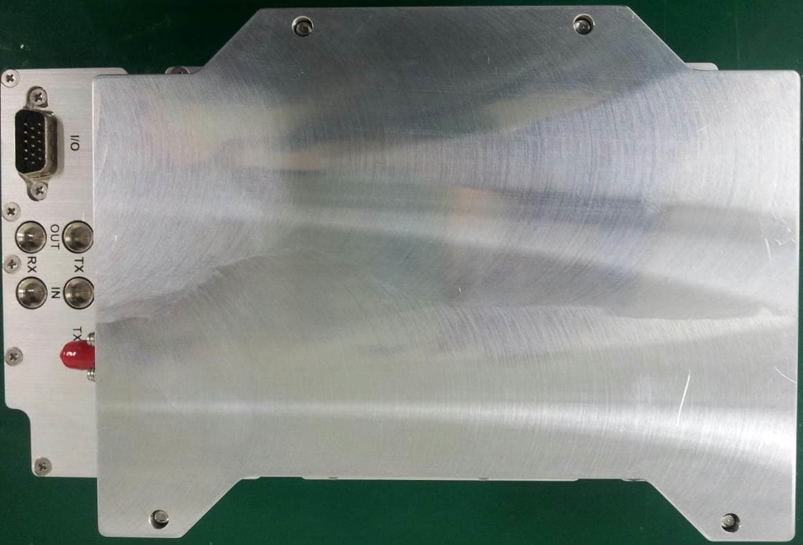
Click to zoom
Application Details
- Equipment Class
- B2I - Part 20 Industrial Booster (CMRS)
- Date of Grant
- May 29, 2014
- Application Purpose
- Original Equipment
- Date of Application
- Mar 31, 2014
- Equipment Note
- 5 Watt 700MHz Amplifier
- Frequency Range
- 728.00000000 - 756.00000000
- Company
- SOLiD, Inc.
- Country
- South Korea
Documents & Files
Document Text
Text extracted from the exhibit documents filed with the FCC. Open a document above to read the original.
Users Manual
Confidential & Proprietary 1/30 Hercules‐S (5W Remote Unit) User Manual SOLiD, Inc. 10,9th Floor, SOLiD Space220 Pangyoyeok‐ro, Bundang‐gu, Seongnam‐si, Gyeonggi‐do, Korea 393‐400 Tel : +82‐31‐627‐6290 Fax : +82‐31‐627‐6209 Confidential & Proprietary 2/30 REVISION HISTORY Version Issue Date No. of Pages Initials Details of Revision Changes V 1.0 Oct. 23, 2013 Original Technical Support SOLiD serial numbers must be available to authorize technical support and/or to establish a return authorization for defective units. The serial numbers are located on the back of the unit, as well as on the box in which they were delivered. Additional support information may be obtained by accessing the SOLiD Tehcnology, Inc. website at www.solid.co.kr or send email at [email protected] This manual is produced by Global Business Division Business Team 1. Printed in Korea. Confidential & Proprietary 3/30 Contents Section1 Safety & Certification Notice ......................................................................... 5 Section2 Introduction ................................................................................................ 8 2.1 Purpose ............................................................................................................. 9 2.2 HERCULES‐S ..................................................................................................... 10 Section3 Functional Description ................................................................................ 11 3.1 General ........................................................................................................... 12 3.2 Component of HERCULES‐S Remote Unit ........................................................... 13 3.3 Dimension ....................................................................................................... 15 Section4 System Installation ..................................................................................... 16 4.1 REMOTE UNIT Installation ................................................................................ 18 4.1.1 REMOTE UNIT Enclosure installation ................................................................. 18 4.1.2 Remote Unit Power Cabling .............................................................................. 21 4.1.3 Remote Unit Optical Cabling ............................................................................. 24 4.1.4 GND Terminal Connection................................................................................. 25 4.1.5 Coaxial cable and Antenna Connection .............................................................. 26 Section5 System Specifications ................................................................................. 27 5.1 Physical Specifications ...................................................................................... 28 5.2 RF performance ............................................................................................... 29 5.3 Certification ..................................................................................................... 30 Confidential & Proprietary 4/30 Contents of Figure Figure 3.1 – Remote Unit Block Diagram ............................................................. 12 Figure 3.2 – Inside of Remote Unit ...................................................................... 13 Figure 3.3 – Remote Unit Dimension ................................................................... 15 Figure 4.1 – Exterior of Remote Unit ................................................................... 18 Figure 4.2 – Dimension used to install REMOTE UNIT on the WALL ........................ 19 Figure 4.3 – Horizontal Installation ..................................................................... 20 Figure 4.4 – Installation Clearance ...................................................................... 20 Figure 4.5 – How to Install Remote Unit .............................................................. 20 Confidential & Proprietary 5/30 Section1 Safety & Certification Notice Confidential & Proprietary 6/30 “Only qualified personnel should handle the DAS equipment. Any person involved in installation or service of the DAS should understand and follow these safety guidelines.” ‐ Obey all general and regional safety regulations relating to work on high voltage installations, as well as regulations covering correct use of tools and personal protective equipment. ‐ To prevent electrical shock, switch the main power supply off prior to working with the DAS System or Fiber BDA. Never install or use electrical equipment in a wet location or during a lightning storm. ‐ When working with units outdoors, make sure to securely fasten the door or cover in an open position to prevent the door from slamming shut in windy conditions. ‐ Use this unit only for the purpose specified by the manufacturer. Do not modify or fit any spare parts that are not sold or recommended by the manufacturer. This could cause fires, electric shock or other injuries. ‐ Any DAS system or Fiber BDA will generate radio (RF) signals and continuously emit RF energy. Avoid prolonged exposure to the antennas. SOLiD recommends maintaining a 2m (78.74 inches) minimum clearance from the antenna while the system is operating. ‐ Do not operate this unit on or close to flammable materials, as the unit may reach high temperatures due to power dissipation. ‐ Do not use any solvents, chemicals, or cleaning solutions containing alcohol, ammonia, or abrasives on the DAS equipment. Alcohol may be used to clean fiber optic cabling ends and connectors. ‐ Do not look into the ends of any optical fiber or directly into the optical transceiver of any digital unit. Use an optical spectrum analyzer to verify active fibers. Place a protective cap over any radiating transceiver or optical fiber connector to avoid the potential of radiation exposure. ‐ Allow sufficient fiber length to permit routing without severe ben…
Text truncated - open the document above for the full version.
Cover Letter(s)
SOLiD, Inc. 10,9th Floor, SOLiD Space 220 Pangyoyeok-ro, Bundang-gu, Seongnam-si, Gyeonggi-do, Korea 463-400 Tel : +82-31-627-6290 Fax : +82-31-627-6209 Request for Confidentiality Date : February 04, 2013 Subject: Confidentiality Request for: FCC ID: W6UHM700L Pursuant to FCC 47 CRF 0.457(d) and 0.459 and IC RSP-100, Section 10, the applicant requests that a part of the subject FCC/IC application be held confidential. Exhibit Permanent Block Diagrams Permanent Operation Description/Theory of Operation Permanent Parts List & Placement/BOM Permanent Tune-Up Procedure Permanent Schematics SOLiD has spent substantial effort in developing this product and it is one of the first of its kind in industry. Having the subject information easily available to "competition" would negate the advantage they have achieved by developing this product. Not protecting the details of the design will result in financial hardship. Permanent Confidentiality: The applicant requests the exhibits listed above as permanently confidential be permanently withheld from public review due to materials that contain trade secrets and proprietary information not customarily released to the public. Sincerely, __________________________ Mr. Kang-Yeob, Bae / Director SOLiD, Inc.
Cover Letter(s)
Page 1 of 2 FCC ID: W6UHM700L/W6UHM80I85C/W6UHM1900P/W6UHMAWS1 IC ID: 9354A-HM700L/9354A-HM80I85C/9354A-HM1900P/9354A-AWS1 CT Project: p13a0006 From: Daniel Park Date: 2/22/14 FCC & IC 1. Please provide FCC and IC confidentiality letters with own information only. Please don’t mix with those two IDs together. Also, please stated only confidential exhibits in the letter. Solid – Please refer to updated cover letters. 2. Based on EUT configuration, the Rule Part 90.219 warning label should be included. No specific guidance was found from FCC whether 90.219 label can be exempted. Please clarify whether Rule Part 90.219 warning label can be omitted. Otherwise, please provide. Solid – Please refer to updated labels. 3. Cover Letter for Final Amplification Stage Voltage and Current under rule part 2.1033 (c ) (8). Solid – Please refer to block diagram for this information. 4. The “TX composite Power” limit don’t agree each other within “user manual” and “Tune up” exhibits, especially, 800 & 850 bands. Please verify. Solid – Please refer to updated manual and operational description exhibits. 5. At the page 9 of RF test report, the title is written as “Uplink” instead. It should be printed as “Downlink”. Please correct it. CT – Please refer to updated test report. 6. Please indicate “KDB 986109” in FCC 731 form for filing the application as well. CT – Please note form 731 has this info on page 2. 7. Currently, the RF exposure compliance testing report wasn’t included in this application. Please clarify whether the RF exposure testing result will be provided to reviewer or RF exposure compliance will be addressed at the time of this device installation. If the RF exposure compliance will be addressed at the time of installation, the grant note must state the condition about RF exposure compliance will be addressed at the time of installation. Please clarify. CT – Please see MPE reports. Page 2 of 2 For IC Side: 1. Under RSS-GEN 5.2, supplier should provide the notices and user information in both English and French. Currently, no French has been found. Please provide all the necessary information in French as well. Solid – Please refer to updated manual. 2. RSP-100 section 5.2 b cover letter is missing. Please provide. CT – Please refer IC cover letter. 3. Currently, IC RF exposure compliance was not clearly documented. Please provide how to comply with IC rule. CT – Please see IC RSS 102 reports Response by: SOLID, Inc. & CTL Submitted by: CTL Date: 3/5/2014
Cover Letter(s)
Page 1 of 1 FCC ID: W6UHM700L/W6UHM80I85C/W6UHM1900P/W6UHMAWS1 IC ID: 9354A-HM700L/9354A-HM80I85C/9354A-HM1900P/9354A-AWS1 CT Project: p13a0006 From: Daniel Park Date: 3/7/14 1. In RSS-102 RF exposure exhibits, it seems P 01 or P 02 were used for “Power Density” calculation instead of P mean (P mean = P 01 +3dB). Please re-calculate the “Power Density” and update reports by using P mean . CT – Please see IC RSS 102 reports (Rev2.0). 2. Please verify and provide all the information stated in Section 5.3 RSS-131 for “User Manual”. SOLID – Please see updated manual & theory of operation. Response by: SOLID, Inc. & CTL Submitted by: CTL Date: 3/12/2014
Cover Letter(s)
Page 1 of 1 FCC ID: W6UHM700L/W6UHM80I85C/W6UHM1900P/W6UHMAWS1 IC ID: 9354A-HM700L/9354A-HM80I85C/9354A-HM1900P/9354A-AWS1 CT Project: p13a0006 From: Daniel Park Date: 3/13/14 1. The stated AWS nominal bandwidth(20dB) within the RF test report and the revised user manual( 9. User's manual REV2) is not close. The revised user manual states 45 MHz for 2100( AWS) band on the specification table. However, the RF test report indicates 84.25 MHz for the same AWS band. CTL – Markers 1 and 4 represent the FCC band edges , A.K.A. FCC bandwidth. The other two markers (Mkr2 delta) are for future IC testing if required and are not the FCC bandwidth. Therefore both report and manual list correct values. Response by: CTL Submitted by: CTL Date: 3/18/2014
Cover Letter(s)
220 Pangyoyeok-ro, Bundang-gu, Seongnam-si, Gyeonggi-do, Korea 463-400 Tel : +82-31-627-6290 Fax : +82-31-627-6209 1 May 16, 2014 Compliance Testing 1724 S. Nevada Way Mesa, AZ 85204 To Whom It May Concern: ALLIANCE REL 6 is SOLiD’s multi-carrier, neutral host Distributed Antenna System (DAS), which efficiently delivers wireless RF signals into buildings, campus environments, or any location that is difficult to cover with traditional outdoor macro networks. ALLIANCE DAS supports a broadband frequency range from 150 MHz to 3 GHz to provide coverage for public safety communications, 2-way radio, and commercial wireless service providers. By greatly improving in-building radio environments, the system allows service providers and enterprise locations to deliver high-quality mobile voice and data services at any site whether a public institution or private facility, including: • Shopping malls • Hotels • Corporate and university campus areas • Airports • Hospitals and Clinics • Underground transportation systems • Multi-use stadiums and convention centers The ALLIANCE DAS REL 6 supports both analog (AMPS) and digital (TDMA, CDMA, WCDMA, and LTE) cellular systems in multiple bands through a single strand of fiber for the following communication standards and public interface protocols: • Frequencies: VHF, UHF, 700MHz (LTE and PS), 800MHz (PS and SMR), 850MHz (Cellular), 900MHz (iDEN and Paging), 1900MHz (PCS), 2100MHz (AWS-1), 2.3GHz (WCS), 2.5GHz (BRS/EBS) 220 Pangyoyeok-ro, Bundang-gu, Seongnam-si, Gyeonggi-do, Korea 463-400 Tel : +82-31-627-6290 Fax : +82-31-627-6209 2 • Voice protocols: AMPS, TDMA, CDMA, GSM, iDEN, WCDMA • Data protocols: EDGE, GPRS, WCDMA, CDMA2000, EV-DO, Paging, LTE-FDD, LTE-TDD ALLIANCE DAS REL 6 provides RF POWER CONTROL™ to guarantee power to each carrier as configured in the DAS management software. Each frequency band has a dedicated amplifier. There is no cross-band sharing, which means more power and control per frequency band. ALLIANCE also features advanced filtering capabilities and 4G Certified MIMO in any band. The system supports multiple frequencies in a single unit through the addition of plug-in modules. By delivering multiple signals with a single optical cable, the system does not require additional facilities whenever a new frequency is added. The ALLIANCE multi-carrier system is a flexible and cost-effective neutral host solution offering: Flexible, Scalable • Clustering multiple-buildings (campus) as one coverage • Small footprint • Mix and match remote units (ROUs): low-power 1W (LROU), mid-power 5W (MROU) and high-power 20W (HROU) • Single fiber strand to each remote unit Modular Structures • Modular frequency upgrade • Hot-swap plug-in modules for each frequency • Add additional carriers without the need for additional architecture Multi-Band, Multi Operator • Signals from multiple service providers transmitted simultaneously • Support for multiple operators in a band • Single infrastructure for 150 MHz to 3 GHz Low OPEX, CAPEX • Compact and upgradable design • Ability to utilize pre-existing infrastructure in building • Easy installation, rapid commissioning with Auto ID of system components • SNMP support (Simple Network Management Protocol v2) for web-based management • Remote Management via TCP/IP connection The ALLIANCE DAS REL 6 is comprised of several primary units as well as optional 220 Pangyoyeok-ro, Bundang-gu, Seongnam-si, Gyeonggi-do, Korea 463-400 Tel : +82-31-627-6290 Fax : +82-31-627-6209 3 units including: • BTS Interface Unit (BIU) • Optical Distribution Unit (ODU) • Remote Optic Unit (ROU) *Available in low-power 1W (LROU), mid-power 5W (MROU) and high-power 20W (HROU) models • DAS Management System (DMS-1200 REL 6) • Add-On Remote Units (AOR and ARU) (Optional to support additional bands) • Optic Expansion Unit (OEU) (Optional fiber MUX to support highly distributed systems) • Link Balancer Unit (Optional DAS interface tray) The figure shows a typical system topology with the BIU, DMS-1200, ODU, and multiple ROUs. The figure also shows the optional OEU and Link Balancer Units. Figure.1 – ALLIANCE DAS Topology The BIU receives the downlink signals from a base station unit (BTS) or bi-directional amplifier (BDA), combines them, and sends them to the ODU via coax. The ODU converts the RF signals to optical signals and transmits them via fiber to the ROUs. At the ROU, signals are amplified and sent via coax to the remote antennas placed throughout the building or campus. Add-on remotes can be connected to the main ROUs to support additional bands. For the uplink path from the mobile device to the BTS or BDA, the process is reversed so that the BIU can route each frequency to the proper carrier. The DMS-1200 is a network management device that provides remote control and monitoring of the DAS through a standard Internet connection. The OEU is an optional fiber MUX device that is used to connect additional ROUs via fiber when extending the DAS from one building to others within the same campus. The Link Balancer Unit is an optional DAS interface tray for attenuated downlink and 220 Pangyoyeok-ro, Bundang-gu, Seongnam-si, Gyeonggi-do, Korea 463-400 Tel : +82-31-627-6290 Fax : +82-31-627-6209 4 uplink signals between the DAS and signal source (BTS or BDA). The figure shows a typical system deployment. Figure.2 – ALLIANCE DAS Deployment If there is any further documentation or assistance we can provide for this matter, please do not hesitate to ask. Please consider SOLiD’s past filings as an additional resource. The past filings dealt with our ALLIANCE 1 and 20W ROUs. They work in the same fashion as our new 5W ROU. Sincerely, Kevin Vierling Director of Product Management
Cover Letter(s)
220 Pangyoyeok-ro, Bundang-gu, Seongnam-si, Gyeonggi-do, Korea 463-400 Tel : +82-31-627-6290 Fax : +82-31-627-6209 1 March 18, 2015 Compliance Testing 1724 S. Nevada Way Mesa, AZ 85204 To Whom It May Concern: We have made a change to our User Manual for the following FCC IDs: • W6UHM80I85C • W6UHM700L • W6UHM700LM • W6UHM850C • W6UHM1900P • W6UHMAWS1 • W6UHMAWS1M The following verbiage was removed: "The Manufacturer's rated output power of this equipment is for single carrier operations. For situations when multiple carrier signals are present, the rating would have to be reduced by 3.5 dB, especially where the output signal is re-radiated and can cause interference to adjacent band users. This power reduction is to be by means of input power or gain reduction and not by an attenuator at the output of the device.” This verbiage was removed due to translation error from Korean to English. The statement is incorrect. No replacement verbiage is required. Sincerely, Kevin Vierling Director of Product Management
External Photos
SOLiD, Inc. 10,9th Floor, SOLiD Space 220 Pangyoyeok-ro, Bundang-gu, Seongnam-si, Gyeonggi-do, Korea 463-400 Tel : +82-31-627-6290 Fax : +82-31-627-6209 ___________________________________________________________________________________ 1. Model Name : MRDU-700LTEF / FCC ID : W6UHM700L
ID Label/Location Info
SOLiD, Inc. 10,9th Floor, SOLiD Space 220 Pangyoyeok-ro, Bundang-gu, Seongnam-si, Gyeonggi-do, Korea 463-400 Tel : +82-31-627-6290 Fax : +82-31-627-6209 1) Model Name : MRDU-700LTEF/ FCC ID : W6UHM700L 2) Model Name :MRDU-800IDEN/850CEL/ FCC ID : W6UHM80I85C 3) Model Name :MRDU-1900PCS/ FCC ID : W6UHM1900P ID Label ID Label ID Label WARNING Label WARNING Label WARNING Label 4) Model Name :MRDU-AWS-1 / FCC ID : W6UHMAWS1 ID Label WARNING Label
Internal Photos
SOLiD, Inc. 10,9th Floor, SOLiD Space 220 Pangyoyeok-ro, Bundang-gu, Seongnam-si, Gyeonggi-do, Korea 463-400 Tel : +82-31-627-6290 Fax : +82-31-627-6209 ___________________________________________________________________________________ 1. MRDU-700LTEF
RF Exposure Info
p13a0006_FCC_Part 1.1310_Rev 1.0 Page 2 of 9 Test Report Prepared for: Solid Technologies Model: Alliance 5W ROU Description: Multiple-Enclosure Booster System Chassis: MROU_C_M_AC – ALLIANCE 5W Optical Unit Chassis, AC Power FCC ID: W6UHM700L (Module MRDU-700LTEF - 5 Watt 700 MHz Full Band LTE Amplifier) FCC ID: W6UHM80I85C (Module MRDU-800IDEN/850CEL - 5 Watt 800 & 850 MHz Amplifier) FCC ID: W6UHM1900P (Module MRDU-1900PCS - 5 Watt 1900 MHz Amplifier) FCC ID: W6UHMAWS1 (Module MRDU-AWS-1 - 5 Watt 2100 MHz Amplifier) To FCC Part 1.1310 Date of Issue: April 23, 2014 On the behalf of the applicant: Solid Technologies 4332 E Siesta Lane Phoenix, AZ 85050 Attention of: Gregory Glenn Ph: (408) 649-4803 E-Mail: [email protected] Prepared By Compliance Testing, LLC 1724 S. Nevada Way Mesa, AZ 85204 (480) 926-3100 phone / (480) 926-3598 fax www.compliancetesting.com Project No: p13a0006 Mike Graffeo Project Test Engineer This report may not be reproduced, except in full, without written permission from Compliance Testing All results contained herein relate only to the sample tested p13a0006_FCC_Part 1.1310_Rev 1.0 Page 3 of 9 Test Report Revision History Revision Date Revised By Reason for Revision 1.0 April 23, 2014 Mike Graffeo Original Document p13a0006_FCC_Part 1.1310_Rev 1.0 Page 4 of 9 ILAC / A2LA Compliance Testing, LLC, has been accredited in accordance with the recognized International Standard ISO/IEC 17025:2005. This accreditation demonstrates technical competence for a defined scope and the operation of a laboratory quality management system (refer joint ISO-ILAC-IAF Communiqué dated January 2009) The tests results contained within this test report all fall within our scope of accreditation, unless below Please refer to http://www.compliancetesting.com/labscope.html for current scope of accreditation. Testing Certificate Number: 2152.01 FCC Site Reg. #349717 IC Site Reg. #2044A-2 Non-accredited tests contained in this report: N/A p13a0006_FCC_Part 1.1310_Rev 1.0 Page 5 of 9 Description: 5W 700MHz Full Band LTE Amplifier This is a permanently mounted (fixed) cell phone booster device used in Controlled Exposure environment. Limits - Controlled Exposure 47 CFR 1.1310 Table 1, (A) 0.3-3.0 MHz: Limit [mW/cm²] = 100 3.0-30 MHz: Limit [mW/cm²] = (900/f²) 30-300 MHz: Limit [mW/cm²] = 1.0 300-1500 MHz: Limit [mW/cm²] = f/300 1500-100,000 MHz Limit [mW/cm²] = 5 Test Frequencies: 742 MHz Power, Conducted: 5000 mW (P) Antenna Gain Isotropic: 11.0 dBi Antenna Gain Numeric (G): 12.59 Antenna Type: Stadium PI = 3.1414 Limit (S): 2.473 mW/cm² Minimum Safe Distance Calculations Formula = R=((PG)/(4*PI*S)) 0.5 Minimum Safe Distance (R) = 45.02 cm p13a0006_FCC_Part 1.1310_Rev 1.0 Page 6 of 9 Description: 5 Watt 800/850MHz Amplifier This is a permanently mounted (fixed) cell phone booster device used in Controlled Exposure environment. Limits - Controlled Exposure 47 CFR 1.1310 Table 1, (A) 0.3-3.0 MHz: Limit [mW/cm²] = 100 3.0-30 MHz: Limit [mW/cm²] = (900/f²) 30-300 MHz: Limit [mW/cm²] = 1.0 300-1500 MHz: Limit [mW/cm²] = f/300 1500-100,000 MHz Limit [mW/cm²] = 5 Test Frequencies: 865.5 MHz Power, Conducted: 5000 mW (P) Antenna Gain Isotropic: 11.6 dBi Antenna Gain Numeric (G): 14.45 Antenna Type: Stadium PI = 3.1414 Limit (S): 2.885 mW/cm² Minimum Safe Distance Calculations Formula = R=((PG)/(4*PI*S)) 0.5 Minimum Safe Distance (R) = 44.65 cm Test Frequencies: 881.5 MHz Power, Conducted: 5000 mW (P) Antenna Gain Isotropic: 11.6 dBi Antenna Gain Numeric (G): 14.45 Antenna Type: Stadium PI = 3.1414 Limit (S): 2.938 mW/cm² Minimum Safe Distance Calculations Formula = R=((PG)/(4*PI*S)) 0.5 Minimum Safe Distance (R) = 44.25 cm p13a0006_FCC_Part 1.1310_Rev 1.0 Page 7 of 9 Description: 5 Watt 1900MHz Amplifier This is a permanently mounted (fixed) cell phone booster device used in Controlled Exposure environment. Limits - Controlled Exposure 47 CFR 1.1310 Table 1, (A) 0.3-3.0 MHz: Limit [mW/cm²] = 100 3.0-30 MHz: Limit [mW/cm²] = (900/f²) 30-300 MHz: Limit [mW/cm²] = 1.0 300-1500 MHz: Limit [mW/cm²] = f/300 1500-100,000 MHz Limit [mW/cm²] = 5 Test Frequencies: 1962.5 MHz Power, Conducted: 5000 mW (P) Antenna Gain Isotropic: 11.6 dBi Antenna Gain Numeric (G): 14.45 Antenna Type: Stadium PI = 3.1414 Limit (S): 5 mW/cm² Minimum Safe Distance Calculations Formula = R=((PG)/(4*PI*S)) 0.5 Minimum Safe Distance (R) = 33.92 cm p13a0006_FCC_Part 1.1310_Rev 1.0 Page 8 of 9 Description: 5 Watt 2100MHz Amplifier This is a permanently mounted (fixed) cell phone booster device used in Controlled Exposure environment. Limits - Controlled Exposure 47 CFR 1.1310 Table 1, (A) 0.3-3.0 MHz: Limit [mW/cm²] = 100 3.0-30 MHz: Limit [mW/cm²] = (900/f²) 30-300 MHz: Limit [mW/cm²] = 1.0 300-1500 MHz: Limit [mW/cm²] = f/300 1500-100,000 MHz Limit [mW/cm²] = 5 Test Frequencies: 2132.5 MHz Power, Conducted: 5000 mW (P) Antenna Gain Isotropic: 11.6 dBi Antenna Gain Numeric (G): 14.45 Antenna Type: Stadium PI = 3.1414 Limit (S): 5 mW/cm² Minimum Safe Distance Calculations Formula = R=((PG)/(4*PI*S)) 0.5 Minimum Safe Distance (R) = 33.92 cm p13a0006_FCC_Part 1.1310_Rev 1.0 Page 9 of 9 Description: Worse case composite 20Watt: if all 4 amplifiers are simultaneously transmitting within the single enclosure (20000mW). Minimum Safe Distance is based off the highest antenna gain of 14.45 and the strictest limit of 2.473 mW/cm². Minimum Safe Distance Calculations Formula = R=((PG)/(4*PI*S)) 0.5 =((20000*14.45)/(4*PI*2.473))^0.5 Minimum Safe Distance (R) = 96.44 cm END OF TEST REPORT
Test Report
p13a0006_W6UHM700L_FCC_Part 22H, 24E, 27_Rev 1.0 Page 1 of 25 Test Report Prepared for: Solid Technologies Model: Alliance 5W ROU Description: Multiple-Enclosure Booster System Chassis: MROU_C_M_AC – ALLIANCE 5W Optical Unit Chassis, AC Power FCC ID: W6UHM700L (Module MRDU-700LTEF - 5 Watt 700 MHz Full Band LTE Amplifier) To FCC Part 22H, 24E, 27 Date of Issue: May 15, 2014 On the behalf of the applicant: Solid Technologies 4332 E Siesta Lane Phoenix, AZ 85050 Attention of: Gregory Glenn (408) 649-4803 E-Mail: [email protected] Prepared By Compliance Testing, LLC 1724 S. Nevada Way Mesa, AZ 85204 (480) 926-3100 phone / (480) 926-3598 fax www.compliancetesting.com Project No: p13a0006 Mike Graffeo Project Test Engineer This report may not be reproduced, except in full, without written permission from Compliance Testing All results contained herein relate only to the sample tested p13a0006_W6UHM700L_FCC_Part 22H, 24E, 27_Rev 1.0 Page 2 of 25 Test Report Revision History Revision Date Revised By Reason for Revision 1.0 5/15/14 Mike Graffeo Original Document p13a0006_W6UHM700L_FCC_Part 22H, 24E, 27_Rev 1.0 Page 3 of 25 Table of Contents Description Page Standard Test Conditions and Engineering Practices 5 Test Result Summary 6 Carrier Output Power 7 Spurious Emissions (Transmitter Conducted) 9 Spurious Emissions (Transmitter Radiated) 11 Intermodulation 14 Occupied Bandwidth 19 Out of Band Rejection 23 Test Equipment Utilized 25 p13a0006_W6UHM700L_FCC_Part 22H, 24E, 27_Rev 1.0 Page 4 of 25 ILAC / A2LA Compliance Testing, LLC, has been accredited in accordance with the recognized International Standard ISO/IEC 17025:2005. This accreditation demonstrates technical competence for a defined scope and the operation of a laboratory quality management system (refer joint ISO-ILAC-IAF Communiqué dated January 2009) The tests results contained within this test report all fall within our scope of accreditation, unless noted below. Please refer to http://www.compliancetesting.com/labscope.html for current scope of accreditation. Testing Certificate Number: 2152.01 FCC Site Reg. #349717 IC Site Reg. #2044A-2 Non-accredited tests contained in this report: N/A p13a0006_W6UHM700L_FCC_Part 22H, 24E, 27_Rev 1.0 Page 5 of 25 Test and Measurement Data Subpart 2.1033(c)(14): All tests and measurement data shown were performed in accordance with FCC Rules and Regulations, Part 2, Subpart J and the following individual Parts: 22H, 24E, 27 Signal Booster. Standard Test Conditions and Engineering Practices Except as noted herein, the following conditions and procedures were observed during the testing. In accordance with ANSI/C63.4-2009, and unless otherwise indicated in the specific measurement results, the ambient temperature of the actual EUT was maintained within the range of 10° to 40°C (50° to 104°F) unless the particular equipment requirements specify testing over a different temperature range. Also, unless otherwise indicated, the humidity levels were in the range of 10% to 90% relative humidity. Environmental Conditions Temp (ºC) Humidity (%) Pressure (mbar) 21.6 - 29.0 40.2 - 57.9 964.7 - 969.4 Measurement results, unless otherwise noted, are worst-case measurements. EUT Description Model: Alliance 5W ROU Description: Multiple-Enclosure Booster System Firmware: N/A Software: N/A Accessories: None Cables: None Modifications: None Additional Information: The EUT is an amplifier for boosting the signal of cellular phone signals and data communication devices. The following frequency bands and emission types are utilized. Frequency Band (MHz) Downlink 728 to 756 Emission Designator G7D EUT Operation during Tests The EUT was in a normal operating condition. p13a0006_W6UHM700L_FCC_Part 22H, 24E, 27_Rev 1.0 Page 6 of 25 Test Result Summary Specification Test Name Pass, Fail, N/A Comments Part 22H, 24E, 27 Carrier Output Power Pass Part 22H, 24E, 27 Spurious Emissions (Transmitter Conducted) Pass Part 22H, 24E, 27 Spurious Emissions (Transmitter Radiated) Pass Part 22H, 24E, 27 Intermodulation Pass Part 22H, 24E, 27 Occupied Bandwidth Pass Part 22H, 24E, 27 Out of Band Rejection Pass Part 22H, 24E, 27 Frequency Stability (Temperature Variation) N/A The EUT does not perform frequency translation Part 22H, 24E, 27 Frequency Stability (Voltage Variation) N/A The EUT does not perform frequency translation p13a0006_W6UHM700L_FCC_Part 22H, 24E, 27_Rev 1.0 Page 7 of 25 Carrier Output Power Name of Test: Carrier Output Power Engineer: Mike Graffeo Test Equipment Utilized: S/N:101369, S/N: AY3295, i00331 Test Date: 11/19/2013 Test Procedure The EUT was connected to a spectrum analyzer through a 40 dB power attenuator. A signal generator was utilized to produce a CW input signal. The RF input level was increased while monitoring the output power. The input RF drive level was increased until the EUT output reached saturation (the output stopped increasing) whereby the maximum power level and gain was achieved. The uplink / downlink power and gain levels for the low, middle, and high channels are recorded in the following tables. Test Setup Signal Generator EUT 40 dB Power Attenuator Spectrum Analyzer p13a0006_W6UHM700L_FCC_Part 22H, 24E, 27_Rev 1.0 Page 8 of 25 Downlink Test Results 728 - 756 MHz Band Tuned Frequency (MHz) Input Power (dBm) Output Power (dBm) Gain (dB) 728.0 -23.6 37 60.6 742.0 -23.8 37 60.8 756.0 -22.2 37 59.2 p13a0006_W6UHM700L_FCC_Part 22H, 24E, 27_Rev 1.0 Page 9 of 25 Spurious Emissions (Transmitter Conducted) Name of Test: Spurious Emissions (Transmitter Conducted) Engineer…
Text truncated - open the document above for the full version.
Contact Information
Applicant
Yong Chul Kim(Team Manager)
Test Firm
Compliance Testing, LLCMichael Schafer
Technical Specifications
| # | Rule Parts | Frequency Range | Power Output | Emission |
|---|---|---|---|---|
| 1 | 27 | 728 MHz - 756 MHz | 5 W | G7D |
Other Applications from SOLiD, Inc.
May 21, 2026
Equipment Class
B9B - Part 90 Class B Industrial Booster (non-SMR)W6UNMRFM25
Mar 17, 2026nGENESIS
Equipment Class
B2I - Part 20 Industrial Booster (CMRS)W6UNMRFM34
Mar 17, 2026nGENESIS
Equipment Class
B2I - Part 20 Industrial Booster (CMRS)W6UNHRFM34
Mar 17, 2026nGENESIS
Equipment Class
B2I - Part 20 Industrial Booster (CMRS)W6UNMRFM40
Mar 17, 2026nGENESIS
Equipment Class
B2I - Part 20 Industrial Booster (CMRS)