W6UHM700LM5 Watt 700MHz Amplifier Module
SOLiD, Inc.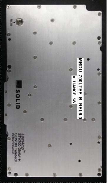
Click to zoom
Application Details
- Equipment Class
- B2I - Part 20 Industrial Booster (CMRS)
- Date of Grant
- Jun 10, 2014
- Application Purpose
- Original Equipment
- Date of Application
- Jun 10, 2014
- Equipment Note
- 5 Watt 700MHz Amplifier Module
- Frequency Range
- 728.00000000 - 756.00000000
- Company
- SOLiD, Inc.
- Country
- South Korea
Documents & Files
Document Text
Text extracted from the exhibit documents filed with the FCC. Open a document above to read the original.
Users Manual
Confidential & Proprietary 1/30 Hercules‐S (5W Remote Unit) User Manual SOLiD, Inc. 10,9th Floor, SOLiD Space220 Pangyoyeok‐ro, Bundang‐gu, Seongnam‐si, Gyeonggi‐do, Korea 393‐400 Tel : +82‐31‐627‐6290 Fax : +82‐31‐627‐6209 Confidential & Proprietary 2/30 REVISION HISTORY Version Issue Date No. of Pages Initials Details of Revision Changes V 1.0 Oct. 23, 2013 Original Technical Support SOLiD serial numbers must be available to authorize technical support and/or to establish a return authorization for defective units. The serial numbers are located on the back of the unit, as well as on the box in which they were delivered. Additional support information may be obtained by accessing the SOLiD Tehcnology, Inc. website at www.solid.co.kr or send email at [email protected] This manual is produced by Global Business Division Business Team 1. Printed in Korea. Confidential & Proprietary 3/30 Contents Section1 Safety & Certification Notice ......................................................................... 5 Section2 Introduction ................................................................................................ 8 2.1 Purpose ............................................................................................................. 9 2.2 HERCULES‐S ..................................................................................................... 10 Section3 Functional Description ................................................................................ 11 3.1 General ........................................................................................................... 12 3.2 Component of HERCULES‐S Remote Unit ........................................................... 13 3.3 Dimension ....................................................................................................... 15 Section4 System Installation ..................................................................................... 16 4.1 REMOTE UNIT Installation ................................................................................ 18 4.1.1 REMOTE UNIT Enclosure installation ................................................................. 18 4.1.2 Remote Unit Power Cabling .............................................................................. 21 4.1.3 Remote Unit Optical Cabling ............................................................................. 24 4.1.4 GND Terminal Connection................................................................................. 25 4.1.5 Coaxial cable and Antenna Connection .............................................................. 26 Section5 System Specifications ................................................................................. 27 5.1 Physical Specifications ...................................................................................... 28 5.2 RF performance ............................................................................................... 29 5.3 Certification ..................................................................................................... 30 Confidential & Proprietary 4/30 Contents of Figure Figure 3.1 – Remote Unit Block Diagram ............................................................. 12 Figure 3.2 – Inside of Remote Unit ...................................................................... 13 Figure 3.3 – Remote Unit Dimension ................................................................... 15 Figure 4.1 – Exterior of Remote Unit ................................................................... 18 Figure 4.2 – Dimension used to install REMOTE UNIT on the WALL ........................ 19 Figure 4.3 – Horizontal Installation ..................................................................... 20 Figure 4.4 – Installation Clearance ...................................................................... 20 Figure 4.5 – How to Install Remote Unit .............................................................. 20 Confidential & Proprietary 5/30 Section1 Safety & Certification Notice Confidential & Proprietary 6/30 “Only qualified personnel should handle the DAS equipment. Any person involved in installation or service of the DAS should understand and follow these safety guidelines.” ‐ Obey all general and regional safety regulations relating to work on high voltage installations, as well as regulations covering correct use of tools and personal protective equipment. ‐ To prevent electrical shock, switch the main power supply off prior to working with the DAS System or Fiber BDA. Never install or use electrical equipment in a wet location or during a lightning storm. ‐ When working with units outdoors, make sure to securely fasten the door or cover in an open position to prevent the door from slamming shut in windy conditions. ‐ Use this unit only for the purpose specified by the manufacturer. Do not modify or fit any spare parts that are not sold or recommended by the manufacturer. This could cause fires, electric shock or other injuries. ‐ Any DAS system or Fiber BDA will generate radio (RF) signals and continuously emit RF energy. Avoid prolonged exposure to the antennas. SOLiD recommends maintaining a 2m (78.74 inches) minimum clearance from the antenna while the system is operating. ‐ Do not operate this unit on or close to flammable materials, as the unit may reach high temperatures due to power dissipation. ‐ Do not use any solvents, chemicals, or cleaning solutions containing alcohol, ammonia, or abrasives on the DAS equipment. Alcohol may be used to clean fiber optic cabling ends and connectors. ‐ Do not look into the ends of any optical fiber or directly into the optical transceiver of any digital unit. Use an optical spectrum analyzer to verify active fibers. Place a protective cap over any radiating transceiver or optical fiber connector to avoid the potential of radiation exposure. ‐ Allow sufficient fiber length to permit routing without severe ben…
Text truncated - open the document above for the full version.
Attestation Statements
SOLiD, Inc. 10,9th Floor, SOLiD Space 220 Pangyoyeok-ro, Bundang-gu, Seongnam-si, Gyeonggi-do, Korea 463-400 Tel : +82-31-627-6290 Fax : +82-31-627-6209 ________________________________________________________________________________ Date : February 04, 2014 Federal Communications Commission Authorization & Evaluation Division 7345 Oakland Mills Road Columbia, Maryland 21046 To Whom It May Concern: According to KDB 935210 D01 , 4 Industrial Signal Booster Part 20, subpart d 1, we as manufacturer, SOLiD declare that the warning below: Can be seen at: - Product itself as label - Packaging as label - Manual - Dasta sheet - Sales brochure - All other electronic media where customer has access ___________________________ Mr. Kang-Yeob, Bae / Director SOLiD, Inc.
Attestation Statements
file:///L|/Project/2014/p1440025-Solid Tec/TCB Folder/MIMO Email.htm[8/8/2014 2:22:57 PM] Subject:FWD: 5Watt MIMO Solution Date:Friday, August 08, 2014 12:10 pm Linked to:Kevin Vierling Jr From:JOHNE (John Erhard) <GoldMine User> To:AMANDAR (Amanda Reed) <GoldMine User> ----------------------- Forwarded Message ----------------------- From: Kevin Vierling <[email protected]> To: "<[email protected]>" <[email protected]>, Jennifer Sanchez <[email protected]> Cc: Date: Fri, 8 Aug 2014 13:07:43 -0600 Subject: 5Watt MIMO Solution MRDU_700LTEF_M Each port on our amplifier is completely independent from each other. In order to achieve MIMO functionality, these paths never cross. When used in conduction with the SISO version, we can send the two paths over a single fiber but still maintain isolation. At the amplifier, the frequencies are boosted but still maintain separation via different antennas. -- KEVIN VIERLING, DIRECTOR OF PRODUCT MANAGEMENT T 856.904.0422 | E [email protected] HQ: 617 N MARY AVE | SUNNYVALE CA 94085 MAIN: 888.409.9997 | www.SOLiD.com SOLiD BLOG TWITTER YOUTUBE LINKEDIN
Cover Letter(s)
Page 1 of 1 FCC ID: W6UHM700LM IC ID: CT Project:P1440025 From: Daniel Park Date: 5/27/14 1. Please add the rule part #27 at the page 6 of User manual. 2. In KDB “935210 D02 Signal Booster Certification v02” states about the RF Exposure compliance at th page3. Please provide the RF exposure compliance report. CT – Mike Graffeo: Report has been added to the TCB uploaded Docs directory (p1440024-25- 26_FCC_Part 1.1310_Rev 1.0.pdf) Response by: Submitted by: Date:
Cover Letter(s)
220 Pangyoyeok-ro, Bundang-gu, Seongnam-si, Gyeonggi-do, Korea 463-400 Tel : +82-31-627-6290 Fax : +82-31-627-6209 1 March 18, 2015 Compliance Testing 1724 S. Nevada Way Mesa, AZ 85204 To Whom It May Concern: We have made a change to our User Manual for the following FCC IDs: • W6UHM80I85C • W6UHM700L • W6UHM700LM • W6UHM850C • W6UHM1900P • W6UHMAWS1 • W6UHMAWS1M The following verbiage was removed: "The Manufacturer's rated output power of this equipment is for single carrier operations. For situations when multiple carrier signals are present, the rating would have to be reduced by 3.5 dB, especially where the output signal is re-radiated and can cause interference to adjacent band users. This power reduction is to be by means of input power or gain reduction and not by an attenuator at the output of the device.” This verbiage was removed due to translation error from Korean to English. The statement is incorrect. No replacement verbiage is required. Sincerely, Kevin Vierling Director of Product Management
External Photos
SOLiD, Inc. 10,9th Floor, SOLiD Space 220 Pangyoyeok-ro, Bundang-gu, Seongnam-si, Gyeonggi-do, Korea 463-400 Tel : +82-31-627-6290 Fax : +82-31-627-6209 ___________________________________________________________________________________ 1. Model Name : MRDU-700LTEF_M / FCC ID : W6UHM700LM
ID Label/Location Info
SOLiD, Inc. 10,9th Floor, SOLiD Space 220 Pangyoyeok-ro, Bundang-gu, Seongnam-si, Gyeonggi-do, Korea 463-400 Tel : +82-31-627-6290 Fax : +82-31-627-6209 ___________________________________________________________________________________ 1. Model Name : MRDU-700LTEF_M / FCC ID : W6UHM700LM ID Label WARNING Label SOLiD, Inc. 10,9th Floor, SOLiD Space 220 Pangyoyeok-ro, Bundang-gu, Seongnam-si, Gyeonggi-do, Korea 463-400 Tel : +82-31-627-6290 Fax : +82-31-627-6209 ________________________________________________________________________________ 1) MODEL NAME : MRDU-700LTEF_M FCC ID : W6UHM700LM Model : MRDU‐700LTEF_M Made in KOREA IC : 9354A‐HM700LM
Internal Photos
SOLiD, Inc. 10,9th Floor, SOLiD Space 220 Pangyoyeok-ro, Bundang-gu, Seongnam-si, Gyeonggi-do, Korea 463-400 Tel : +82-31-627-6290 Fax : +82-31-627-6209 ___________________________________________________________________________________ 1. Model Name : MRDU-700LTEF_M / FCC ID : W6UHM700LM
RF Exposure Info
p1440024-25-26_FCC_Part 1.1310_Rev 1.0 Page 1 of 4 Test Report Prepared for: Solid Technologies Model: EXPRESS Public Safety Description: Booster System FCC ID’s: W6UHM850C, W6UHM700LM, W6UHMAWS1M To FCC Part 1.1310 Date of Issue: May 16, 2014 On the behalf of the applicant: Solid Technologies 4332 E Siesta Lane Phoenix, AZ 85050 Attention of: Gregory Glenn Ph: (408) 649-4803 E-Mail: [email protected] Prepared By Compliance Testing, LLC 1724 S. Nevada Way Mesa, AZ 85204 (480) 926-3100 phone / (480) 926-3598 fax www.compliancetesting.com Project No: p1440024-25-26 Mike Graffeo Project Test Engineer This report may not be reproduced, except in full, without written permission from Compliance Testing All results contained herein relate only to the sample tested p1440024-25-26_FCC_Part 1.1310_Rev 1.0 Page 2 of 4 Test Report Revision History Revision Date Revised By Reason for Revision 1.0 May 16, 2014 Mike Graffeo Original Document p1440024-25-26_FCC_Part 1.1310_Rev 1.0 Page 3 of 4 ILAC / A2LA Compliance Testing, LLC, has been accredited in accordance with the recognized International Standard ISO/IEC 17025:2005. This accreditation demonstrates technical competence for a defined scope and the operation of a laboratory quality management system (refer joint ISO-ILAC-IAF Communiqué dated January 2009) The tests results contained within this test report all fall within our scope of accreditation, unless below Please refer to http://www.compliancetesting.com/labscope.html for current scope of accreditation. Testing Certificate Number: 2152.01 FCC Site Reg. #349717 IC Site Reg. #2044A-2 Non-accredited tests contained in this report: N/A p1440024-25-26_FCC_Part 1.1310_Rev 1.0 Page 4 of 4 Description: Worse case composite 15 Watts: if all three amplifiers are simultaneously transmitting within the single enclosure (15,000mW). Minimum Safe Distance is based off the highest antenna gain of 14.45 and the strictest limit of 2.473 mW/cm^2 Minimum Safe Distance Calculations Formula = R=((PG)/(4*PI*S)) 0.5 =((15,000*14.45)/(4*PI*2.473))^0.5 Minimum Safe Distance (R) = 83.52cm END OF TEST REPORT
RF Exposure Info
•Most widely used stadium antenna •Large box indoor coverage •Includes flexible stadium bracket •Broadband radiators •Suitable for LTE/CDMA/UMTS/GSM All Specifications are subject to change. Refer to www.cssantenna.com for the most current information www.cssantenna.com 410-612-0080 [email protected] Page 1 of 12 1/21/2013 All Specifications are subject to change. Refer to www.cssantenna.com for the most current information www.cssantenna.com 410-612-0080 [email protected] Page 2 of 12 1/21/2013 -25 -15 -5 5 15 0 10 20 30 40 50 60 70 80 90 100 110 120 130 140 150 160 170 180 190 200 210 220 230 240 250 260 270 280 290 300 310 320 330 340 350 XEA-FRO-130 Horizontal Pat Vertical Pat Frequency: 750 MHz All Specifications are subject to change. Refer to www.cssantenna.com for the most current information www.cssantenna.com 410-612-0080 [email protected] Page 3 of 12 1/21/2013 -25 -15 -5 5 15 0 10 20 30 40 50 60 70 80 90 100 110 120 130 140 150 160 170 180 190 200 210 220 230 240 250 260 270 280 290 300 310 320 330 340 350 XEA-FRO-130 Horizontal Pat Vertical Pat Frequency: 850 MHz All Specifications are subject to change. Refer to www.cssantenna.com for the most current information www.cssantenna.com 410-612-0080 [email protected] Page 4 of 12 1/21/2013 -25 -15 -5 5 15 0 10 20 30 40 50 60 70 80 90 100 110 120 130 140 150 160 170 180 190 200 210 220 230 240 250 260 270 280 290 300 310 320 330 340 350 XEA-FRO-130 Horizontal Pat Vertical Pat Frequency: 1780 MHz All Specifications are subject to change. Refer to www.cssantenna.com for the most current information www.cssantenna.com 410-612-0080 [email protected] Page 5 of 12 1/21/2013 -25 -15 -5 5 15 0 10 20 30 40 50 60 70 80 90 100 110 120 130 140 150 160 170 180 190 200 210 220 230 240 250 260 270 280 290 300 310 320 330 340 350 XEA-FRO-130 Horizontal Pat Vertical Pat Frequency: 1920 MHz All Specifications are subject to change. Refer to www.cssantenna.com for the most current information www.cssantenna.com 410-612-0080 [email protected] Page 6 of 12 1/21/2013 -25 -15 -5 5 15 0 10 20 30 40 50 60 70 80 90 100 110 120 130 140 150 160 170 180 190 200 210 220 230 240 250 260 270 280 290 300 310 320 330 340 350 XEA-FRO-130 Horizontal Pat Vertical Pat Frequency: 2120 MHz All Specifications are subject to change. Refer to www.cssantenna.com for the most current information www.cssantenna.com 410-612-0080 [email protected] Page 7 of 12 1/21/2013 All Specifications are subject to change. Refer to www.cssantenna.com for the most current information www.cssantenna.com 410-612-0080 [email protected] Page 8 of 12 1/21/2013 All Specifications are subject to change. Refer to www.cssantenna.com for the most current information www.cssantenna.com 410-612-0080 [email protected] Page 9 of 12 1/21/2013 All Specifications are subject to change. Refer to www.cssantenna.com for the most current information www.cssantenna.com 410-612-0080 [email protected] Page 10 of 12 1/21/2013 All Specifications are subject to change. Refer to www.cssantenna.com for the most current information www.cssantenna.com 410-612-0080 [email protected] Page 11 of 12 1/21/2013 All Specifications are subject to change. Refer to www.cssantenna.com for the most current information www.cssantenna.com 410-612-0080 [email protected] Page 12 of 12 1/21/2013
Test Report
p1440025_FCC_Part 27_Rev 2.0 Page 1 of 25 Test Report Prepared for: Solid Technologies Model: MRDU-700LTEF-B Description: 5 WATT 700MHz Amplifier Module; Path B for MIMO applications Chassis: ALLIANCE 5W Optical Unit Chassis, AC Power FCC ID: W6UHM700LM To FCC Part 27 Date of Issue: May 15, 2014 On the behalf of the applicant: Solid Technologies 4332 E Siesta Lane Phoenix, AZ 85050 Attention of: Gregory Glenn Ph: (408) 649-4803 E-Mail: [email protected] Prepared By Compliance Testing, LLC 1724 S. Nevada Way Mesa, AZ 85204 (480) 926-3100 phone / (480) 926-3598 fax www.compliancetesting.com Project No: p1440025 Mike Graffeo Project Test Engineer This report may not be reproduced, except in full, without written permission from Compliance Testing All results contained herein relate only to the sample tested p1440025_FCC_Part 27_Rev 2.0 Page 2 of 25 Test Report Revision History Revision Date Revised By Reason for Revision 1.0 5/7/14 Mike Graffeo Original Document 2.0 5/27/14 Mike Graffeo 1) Remove reference to part 22 and part 24 2) Added Output port vs. frequency p1440025_FCC_Part 27_Rev 2.0 Page 3 of 25 Table of Contents Description Page Standard Test Conditions and Engineering Practices 5 Licensing and Module and Frequency Range Cross Reference 6 Test Result Summary 7 Carrier Output Power 8 Spurious Emissions (Transmitter Conducted) 10 Spurious Emissions (Transmitter Radiated) 13 Intermodulation 16 Occupied Bandwidth 19 Out of Band Rejection 23 Test Equipment Utilized 25 p1440025_FCC_Part 27_Rev 2.0 Page 4 of 25 ILAC / A2LA Compliance Testing, LLC, has been accredited in accordance with the recognized International Standard ISO/IEC 17025:2005. This accreditation demonstrates technical competence for a defined scope and the operation of a laboratory quality management system (refer joint ISO-ILAC-IAF Communiqué dated January 2009) The tests results contained within this test report all fall within our scope of accreditation, unless noted below. Please refer to http://www.compliancetesting.com/labscope.html for current scope of accreditation. Testing Certificate Number: 2152.01 FCC Site Reg. #349717 IC Site Reg. #2044A-2 Non-accredited tests contained in this report: N/A p1440025_FCC_Part 27_Rev 2.0 Page 5 of 25 Test and Measurement Data Subpart 2.1033(c)(14): All tests and measurement data shown were performed in accordance with FCC Rules and Regulations, Part 2, Subpart J and the following individual Part 27 Signal Booster. Standard Test Conditions and Engineering Practices Except as noted herein, the following conditions and procedures were observed during the testing. In accordance with ANSI/C63.4-2009, and unless otherwise indicated in the specific measurement results, the ambient temperature of the actual EUT was maintained within the range of 10° to 40°C (50° to 104°F) unless the particular equipment requirements specify testing over a different temperature range. Also, unless otherwise indicated, the humidity levels were in the range of 10% to 90% relative humidity. Environmental Conditions Temp (ºC) Humidity (%) Pressure (mbar) 21.6 - 29.0 40.2 - 57.9 964.7 - 969.4 Measurement results, unless otherwise noted, are worst-case measurements. EUT Description Model: MRDU-700LTEF-B Description: 5 WATT 700MHz Amplifier Module; Path B for MIMO applications Firmware: N/A Software: SOLiD ALLIANCE REL6.0 Management V16.1_03_29_2014 Accessories: None Cables: None Modifications: None Additional Information: The EUT is an amplifier for boosting the signal of cellular phone signals and data communication devices. The following frequency bands and emission types are utilized. It is considered an industrial booster. Antenna Output Port Utilized: Ant 2 Frequency Band (MHz) Downlink 728 to 756 Emission Designator G7D EUT Operation during Tests The EUT was in a normal operating condition. Note: An additional signal generator was needed to be on at all times to provide a “clock” to keep the EUT functioning p1440025_FCC_Part 27_Rev 2.0 Page 6 of 25 Licensing and Module and Frequency Range Cross Reference Module Licensing vs. and Module and Frequency Range FCC ID Model Name Frequency Range (MHz) W6UHM700LM MRDU-700LTEF-B 728 – 756 p1440025_FCC_Part 27_Rev 2.0 Page 7 of 25 Test Result Summary Specification Test Name Pass, Fail, N/A Comments Part 27 Carrier Output Power Pass Part 27 Spurious Emissions (Transmitter Conducted) Pass Part 27 Spurious Emissions (Transmitter Radiated) Pass Part 27 Intermodulation Pass Part 27 Occupied Bandwidth Pass Part 27 Out of Band Rejection Pass Part 27 Frequency Stability (Temperature Variation) N/A The EUT does not perform frequency translation Part 27 Frequency Stability (Voltage Variation) N/A The EUT does not perform frequency translation p1440025_FCC_Part 27_Rev 2.0 Page 8 of 25 Carrier Output Power Name of Test: Carrier Output Power Engineer: Mike Graffeo Test Equipment Utilized: i00405, i00266, i00379 Test Date: 5/5/14 Test Procedure The EUT was connected to a spectrum analyzer through a 40 dB power attenuator. A signal generator was utilized to produce a CW input signal. The RF input level was increased while monitoring the output power. The input RF drive level was increased until the EUT output reached saturation (the output stopped increasing) whereby the maximum power level and gain was achieved. The downlink power and gain levels for the low, middle, and high channels are recorded in the following table. Test Setup Signal Generator EUT 40 dB Power Attenuator Spectrum Analyzer p1440025_FCC_Part 27_Rev 2.0 Page 9 of 25 Downlink Test Results 728 - 756 MHz Band Tuned Frequency (MHz) Input Power (dBm) Output Power (dBm) Gain (dB) 728.0 -13.5 37 50.5 742.0 -14.0 37 51.0 756.0 -13.3 37 50.3 p1440025_FCC_Part 27_Rev 2.0 Page 10 of 25 Spurious Emissions (Transmitter Conducted) Name of Test: Spurious Emissions (Transmitter Conducted) Engineer: Mike Graffeo Test Equipment Utilized: i00405, i00266, i00379 Test Date: 5/8/14 Test Procedure The EUT was connected to a spect…
Text truncated - open the document above for the full version.
Contact Information
Applicant
Yong Chul Kim(Team Manager)
Test Firm
Compliance Testing, LLCSteve Schafer
Technical Specifications
| # | Rule Parts | Frequency Range | Power Output | Emission |
|---|---|---|---|---|
| 1 | 27 | 728 MHz - 756 MHz | 5 W | G7D |
Other Applications from SOLiD, Inc.
May 21, 2026
Equipment Class
B9B - Part 90 Class B Industrial Booster (non-SMR)W6UNMRFM25
Mar 17, 2026nGENESIS
Equipment Class
B2I - Part 20 Industrial Booster (CMRS)W6UNMRFM34
Mar 17, 2026nGENESIS
Equipment Class
B2I - Part 20 Industrial Booster (CMRS)W6UNHRFM34
Mar 17, 2026nGENESIS
Equipment Class
B2I - Part 20 Industrial Booster (CMRS)W6UNMRFM40
Mar 17, 2026nGENESIS
Equipment Class
B2I - Part 20 Industrial Booster (CMRS)