W7670A00-2GSM FIXED WIRELESS TERMINAL WITH PSTN
DEKAI TELECOM CO., LIMITED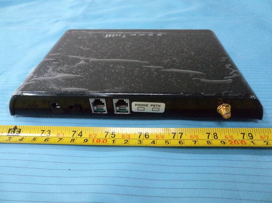
Click to zoom
Application Details
- Equipment Class
- PCB - PCS Licensed Transmitter
- Date of Grant
- Mar 05, 2012
- Application Purpose
- Original Equipment
- Date of Application
- Mar 05, 2012
- Equipment Note
- GSM FIXED WIRELESS TERMINAL WITH PSTN
- Frequency Range
- 1850.20000000 - 1909.80000000
- Company
- DEKAI TELECOM CO., LIMITED
- Country
- Hong Kong
Documents & Files
Document Text
Text extracted from the exhibit documents filed with the FCC. Open a document above to read the original.
Users Manual
DEKAI TELECOM CO., LIMITED 1 Flat 7A, 7/F., Kimley Commercial Bldg.., 142-146 Queen’s Road Central, Hong Kong 999077 TEL:+852 25814966 FAX:+852 28514966 GSM FWT W/ PSTN 70A00-2 (Gateway) User's Manual Brand: HAI Model: 70A00-2 Manufacturer: Dekai Telecom Co., Limited DEKAI TELECOM CO., LIMITED 2 Important Safety Instructions: 1. Read all safety and operating instructions before using. 2. This product should not be used near water. 3. Only use dry cloth to clean this product. 4. Do not block any ventilation openings. 5. Do not install this product near any heat sources; such as, radiators, heat registers, stoves, or other appliances (including heat producing amplifiers) that produce heat. 6. Only use attachments specified by the manufacturer. 7. Unplug this apparatus during lightning storms. 8. Care should be taken so that objects do not fall and liquids are not spilled into the unit through the ventilation ports or any other openings. 9. Refer all servicing to qualified service personnel. 10. Servicing is required when the apparatus has been damaged in any way; such as, a liquid has been spilled or objects have fallen into the apparatus, the apparatus has been exposed to rain or moisture, the apparatus does not operate normally, or has been physically damaged. 11. WARNING:To reduce the risk of fire or electric shock, do not expose this apparatus to rain or moisture. 12. WARNING:Battery(built-in) may explode if mistreated. Do not disassemble or dispose of in fire DEKAI TELECOM CO., LIMITED 3 GSM FWT W/ PSTN 70A00-2 Version 1.1 -2011 1, General Description When PSTN line is connected and active, you will hear a normal dial tone (from the PSTN) after phone is picked up. The call will dial out through PSTN.(Be default) When the FWT is in GSM mode without active PSTN line, you will hear a gsm dial tone (from the FWT) after phone is picked up. The call will dial out through GSM. If PSTN and GSM all are available, you could pick up the phone and enter “* *” (two star keys) before press other digits, the FWT would switch to GSM mode, then the call will dial out through GSM . DEKAI TELECOM CO., LIMITED 4 Available: z GSM850/900/1800/1900Mhz Quadband, employing M10(Quectel) module to make. Appearance and Structure Item GSM&PSTN FWT 70A00-2 Remark Appearance Black Material ABS (Acrylonitrile Butadiene Styrene) Dimension 170mm×118mm×30mm Excluding antenna Weight 250g Weight of Main unit Power Switch Rocker switch Power Socket12V DC input Phone interface RJ11 2 RJ-11 ports Antenna interface SMA-female LED display No.1: Power, No.2.in use, No.3, in talk, No.4, Battery, if have, No. 5-7, Signal strength From left to right(front side view) DEKAI TELECOM CO., LIMITED 5 Front side LEDs display for Signal strength, Power, Working Status, Talking and Battery indicator; Rear side 1pcs SMA antenna connectors, 2 RJ-11 output, Power port and switch; Bottom side 1pcs Sim card holder slots, you can insert Sim card into the slot . 2, Features: 1) Simple to install and easy to maintain 2) Steady module and reliable design ensures good performance 3) Provides optimized circuit directly connecting the exchange device for extensions 4) Compatible to most telephones, PBX device. 5) Strong signals with high gain antenna 6) Attractive plastic casing 7) SIM card supported (1.8V, 3V) 8) Caller ID display 9) Provides reversal polarity signal for metering 10) No noise and clear voice 11) Suitable for wide voltage range and low power consumption 12) Suitable for all kinds of weather and environment 13) RJ-11 ports (1 fxo for pstn line and 1 fxs port) 14) Locking PIN / network (optional) 3,Technical Specifications Air interface standard: GSM850/1900Mhz,900/1,800Mhz phase 2+ full band Frequency ranges: GSM850:824-849MHz(TX);869-894MHz(RX) PCS1900:1850-1910MHz(TX);1930-1990MHz(RX) Phone interface: supply RJ-11 Phone Interface Hanging voltage: 45V Picking off voltage: 30mA / 41mA DEKAI TELECOM CO., LIMITED 6 Dialing tone Frequency: 450Hz Antenna interface: Antenna amplifying>2.5dBi Sensitivity:<-104DBM Transmitting power<3W Color: White /Black (optional) AC-Adapter interface: Input: AC 110~240VAC 50~60Hz Output: 12DC 1A. AC-Adapter type: EU, US, AU, British can be optional 4, Operation Circumstance: Operation temperature: -10c~60C Storage temperature:-20C~70C Operation humidity:45%-95% Atmosphere pressure:86-106Kpa Environment noise: <60DB Transmitting Power:2W Sensitivity: <-104dbm Antenna Amplifying: >2.5db Dialing frequency: 450Hz Hanging voltage: 45V Picking current: 30mA/41mA 5, Packing List Name Quantity Remark GSM FWT W/ PSTN 70A00-2 1pcs Quadband Ac- adapter 1pcs AC-110-240V, DC12V/1A Antenna 1pcs Magnetic Antenna with 3m cable Telephone cable 1pcs 1m cable User's Manual 1pcs English G.W: 0.65kg per unit, 20pcs/CTN, 13kg /CTN, CTN Size: 59cmX35cmX26cm DEKAI TELECOM CO., LIMITED 7 6, Installation and Connection The Condition for Installation The terminal asks for 110- 220V AV power supply. It must be installed in the area where the GSM network can cover. The strength of the signal can affect the quality of voice. 1. Open the rear cover, insert SIM card for every Sim card holder. 2. Install antenna. In order to ensure the quality of voice, antenna must be put beyond 1.5 from the telephone and terminal. 3. On end of the telephone line connects to the “Phone” port of the terminal, the other end connects to telephone. 4. “Power” port connects to power adapter that is connected to 110-220V AC power supply. The Installation for Connecting to PSTN &Ordinary Telephone The Sketch for connecting to PSTN And Ordinary Telephone set. DEKAI TELECOM CO., LIMITED 8 Draw your attention: Because there are many types of ordinary telephone and their electric parameters are different. In order to avoid mutual disturbance between telephone and terminal and affect voice quality. The distance between telephone and terminal is 1.5m at least. 7, Function Setting Before you do the following function settings, Lift handset or press hands free key of …
Text truncated - open the document above for the full version.
External Photos
EXHIBIT B - EUT EXTERNAL PHOTOGRAPHS EUT with the Accessories View EUT – Top View EUT – Bottom View EUT – Port View EUT – Antenna View
ID Label/Location Info
EXHIBIT A - FCC ID LABELING AND LOCATION FCC ID Label FCC ID Label Location The label shown shall be permanently affixed at a conspicuous location on the device and be readily visible to the user at the time purchase (Labeling requirements per 2.925)
Internal Photos
EXHIBIT C - EUT INTERNAL PHOTOGRAPHS EUT – Top Cover off View Antenna connet port EUT – Bottom Cover off View EUT – Main Board Top View Ant.Connect port EUT – RF Module Lable EUT – RF Module Shielding off View EUT – Main Board Bottom View EUT – Auxiliary-1 Board Top View EUT – Auxiliary-1 Board Bottom View EUT – Auxiliary-2 Board Top View EUT – Auxiliary-2 Board Top View EUT – Battery View EUT – Antenna View
Test Report
Note: This test report is prepared for the customer shown above and for the equipment described herein. It may not be duplicated or used in part without prior written consent from Bay Area Compliance Laboratories Corp. This report must not be used by the customer to claim product certification, approval, or endorsement by NVLAP*, or any agency of the Federal Government. * This report contains data that are not covered by the NVLAP accreditation and are marked with an asterisk “★” (Rev.2) FCC PART 22H, PART 24E TEST REPORT For DEKAI TELECOM CO., LIMITED Flat 7A, 7/F, Kimley Commercial Bldg., 142-146 Queen’s Road Central, Hong Kong FCC ID: W7670A00-2 Report Type: Original Report Product Type: GSM FIXED WIRELESS TERMINAL WITH PSTN Test Engineer: Henry Ding Report Number: RSZ111214010-00 Report Date: 2012-03-06 Reviewed By: Alvin Huang EMC Engineer Test Laboratory: Bay Area Compliance Laboratories Corp. (Shenzhen) 6/F, the 3rd Phase of WanLi Industrial Building ShiHua Road, FuTian Free Trade Zone Shenzhen, Guangdong, China Tel: +86-755-33320018 Fax: +86-755-33320008 www.baclcorp.com.cn Bay Area Compliance Laboratories Corp. (Shenzhen) Report No.: RSZ111214010-00 FCC Part 22H/24E Page 2 of 19 TABLE OF CONTENTS GENERAL INFORMATION.......................................................................................................................................3 PRODUCT DESCRIPTION FOR EQUIPMENT UNDER TEST (EUT) .....................................................................................3 OBJECTIVE...................................................................................................................................................................3 RELATED SUBMITTAL(S)/GRANT(S).............................................................................................................................3 TEST METHODOLOGY..................................................................................................................................................3 TEST FACILITY.............................................................................................................................................................4 SYSTEM TEST CONFIGURATION ..........................................................................................................................5 JUSTIFICATION.............................................................................................................................................................5 EQUIPMENT MODIFICATIONS.......................................................................................................................................5 LOCAL SUPPORT EQUIPMENT LIST AND DETAILS........................................................................................................5 EXTERNAL I/O CABLE..................................................................................................................................................5 CONFIGURATION OF TEST SETUP.................................................................................................................................6 BLOCK DIAGRAM OF TEST SETUP................................................................................................................................6 SUMMARY OF TEST RESULTS...............................................................................................................................7 FCC §1.1307 & §2.1091 - RF EXPOSURE INFORMATION ...................................................................................8 APPLICABLE STANDARD..............................................................................................................................................8 FCC §2.1047 - MODULATION CHARACTERISTIC ..............................................................................................9 FCC § 2.1046, § 22.913 (A) & § 24.232 (C) - RF OUTPUT POWER......................................................................10 APPLICABLE STANDARD............................................................................................................................................10 TEST PROCEDURE......................................................................................................................................................10 TEST EQUIPMENT LIST AND DETAILS.........................................................................................................................10 TEST DATA................................................................................................................................................................11 FCC §2.1049, §22.917, §22.905 & §24.238 - OCCUPIED BANDWIDTH ..............................................................13 APPLICABLE STANDARD............................................................................................................................................13 TEST DATA: COMPLIANCE.........................................................................................................................................13 FCC §2.1051, §22.917(A) & §24.238(A) - SPURIOUS EMISSIONS AT ANTENNA TERMINALS ..................14 APPLICABLE STANDARD............................................................................................................................................14 TEST DATA: COMPLIANCE.........................................................................................................................................14 FCC §2.1053, §22.917 & §24.238 - SPURIOUS RADIATED EMISSIONS ...........................................................15 APPLICABLE STANDARD............................................................................................................................................15 TEST PROCEDURE......................................................................................................................................................15 TEST EQUIP…
Text truncated - open the document above for the full version.
Test Setup Photos
EXHIBIT D - TEST SETUP PHOTOGRAPHS Radiated Emissions Extreme Condition
Contact Information
Applicant
Byron Yang(Marketing Executive Director)
Test Firm
Bay Area Compliance Laboratory Corp. (Shenzhen)John Chan
Technical Specifications
| # | Rule Parts | Frequency Range | Power Output | Emission | Tolerance |
|---|---|---|---|---|---|
| 2 | 24E | 1.85 GHz - 1.91 GHz | 759.00 mW | 300KGXW | 2.5 ppm |