WA6I130VERYKOOL I130
VeryKool USA IncApplication Details
- Equipment Class
- JBP - Part 15 Class B Computing Device Peripheral
- Date of Grant
- Jul 24, 2012
- Application Purpose
- Original Equipment
- Date of Application
- Jul 24, 2012
- Equipment Note
- VERYKOOL I130
- Company
- VeryKool USA Inc
- Country
- United States
Documents & Files
Document Text
Text extracted from the exhibit documents filed with the FCC. Open a document above to read the original.
Users Manual
Welcome to use i130 Welcome to use your new product. Registering your new cell phone will take you less than 2 minutes and will give you access to the verykool zone where you will enjoy from promotions, ringtones, technical information, support and much more. Visit: www.verykoolzone.com Functions Description 1.Left soft key (LSK) 8.Receiver 2.Right soft key (RSK) 9. USB jack 3.Send key (Snd) 10.Mic 4.End key (End) 11.Camera 5. Navigation key 12.Flashlight/Torch 6. OK key 13.Speaker 7.Keypad Make a call In the standby mode Input the number Press Snd key to call Make a caller picture call In the standby mode OK Choose one unnamed caller Add Add by hand or import from phonebook Highlight the caller you want to call Press OK to call End a call Press End key Add a new contact Enter Phonebook Scroll to the top and select Add new contact OK Select To SIM/ Phone Choose the field to Edit When finished editing fields, press OK to save Send a msg Messaging Write message Edit message content Once done typing press OK Enter recipient or add from phonebook Press LSK Send Services Extra Applications Services With my i130 I want to... Internet service Input address Press OK key to browse Media player Extra Multimedia Media player My playlists Options Choose New to add one playlist Add music from file manager Press OK to play FM Radio Extra Multimedia FM Radio Plug in your earphone Take a picture Extra Multimedia Camera Press OK key to take pictures Bluetooth Extra Settings Connectivity Bluetooth Power Select to switch on/off Bluetooth Accessories in Package Handset Battery Travel charger Earphone User Guide 1 pcs 1 pcs 1 pcs 1 pcs 1 pcs Security and performance ◆To touch the screen of the mobile phone with sharp articles is prohibited. Dust particles and nails may scratch the screen. Please maintain the screen clean. Please remove the dust on the screen with soft cloth gently, so as not to scratch the screen. ◆In thunder raining days, please do not use the mobile phone when charging it or outdoor, so as to avoid being struck by thunder or other injuries. ◆Please do not put the battery in high-temperature environment (high temperature will lead to heat of the battery upgrading), or else it may result in fire or explosion. ◆Please keep the mobile phone being charged and the charger away from people or other flammable and explosive articles in order to avoid fire, explosion or other dangers! ◆Please strictly adhered to the rules and do shut down the mobile phone on occasions which use of mobile phone is prohibited! ◆Please do not put the mobile phone, battery and charger in the equipment with strong electromagnetic field, such as induction cooker and microwave oven; otherwise it will lead to circuit failure, fire or explosion. ◆Please do not arbitrarily refit the mobile phone, or teardown the mobile phone and accessories without authorization. Improper refitting or teardown easily triggers fire and explosion of the mobile phone. Only the authorized organizations can repair the mobile phone. ◆Please do not use batteries, charger or accessories of non-standard original models. ◆Please do not join the two poles of the battery, so as not to result in battery short-circuit. ◆If the power wire has been damaged (such as the exposed and fractured), or the connector has been loosened, please don’t use it, so as to avoid electric shock, short circuit of the charger or fire. ◆The mobile phone should be powered off in the hospital or other places where use of mobile phone is prohibited. Mobile phone will affect proper work of electronic equipment and medical devices, such as pacemakers, hearing aids and other medical electronic equipments. Pacemaker manufacturer proposes to keep the distance between the mobile phone and the pacemaker at least 15 cm, in order to avoid potential interference to the pacemaker by the mobile phone. ◆Please do not use the mobile phone when driving a car. In case of emergency, please use hand-free devices (which may be bought separately); otherwise, please park your car on the road side before making a call. ◆Please do not put the mobile phone on car insurance airbag or region reachable by the airbag after spreading. Otherwise when the airbag expands or ruptures, the mobile phone is likely to cause serious damage to the people in the car due to strong external force. ◆Please keep the mobile phone, battery and charger at place out of the reach of children. Please do not let children use the mobile phone, battery and charger in the absence of adults’ supervision. ◆In order to comply with provisions of RF leakage, when you wear a mobile phone or use the data functions of the mobile phone, please maintain the distance between the antenna and the body at least 1 inch (2.5 centimeters). ◆Please power off the mobile phone before cleaning and maintenance. If the mobile phone is connected to the charger, you need to unplug the charger from the power outlet, and disconnect the connection between the charger and the mobile phone in order to avoid electric shock, short circuit of battery or charger. ◆Do not use chemical lotion, scrubbing cleanser to wipe the mobile phone or the charger, otherwise it may damage the components or cause fire. Slightly wet and anti-static soft clean cloth can be used. ◆Please do not throw the old and abandoned lithium batteries into trash can, send them to the designated locations or return them to our company. ◆Please do not charge the mobile phone in environment with much dust, humidity, too high, or too low temperature (the permitted charging temperature range is 0°C~ 40°C), and the power wire cannot be nearby the heating containers. ◆Please do not use the phone to make bold to camera, video and recording that may infract the rights of the copyright owners. The company will not be responsible for any losses caused by not recording, deleting, destructing or damage of the photos, video and recordings caused by its accessories or software on the use of the functions includi…
Text truncated - open the document above for the full version.
Block Diagram
SYSTEM BLOCK DIAGRAM Bluetooth 32.768KHz CRYSTAL 26MHz CRYSTAL Keypad T-flash 0.3M camera LCD Module CPU: MT6252A Antenna RF MODULE: SKY77568-11 FM Memory
Cover Letter(s)
Shenzhen MORLAB Communication Technology Co., Ltd. Tel: +86 755 61281201 Fax: +86 755 86130218 3 F, Electronic Testing Building. Shahe Road, Xili, Nanshan Districe, Shenzhen, 518055 P R China Test Lab Attestation Letter Date of Test: 2012‐07‐06 Applicant Name: Verykoo USA Inc FCC Id: WA6I130 Name of Engineer Performing Test: Zhu Zhan (Typed) Statement of Compliance: (Test Lab) declares that this Unit has been tested in accordance with the test method identified in this test report and that we observed it being tested. It also declares that the Unit complies with the relevant limits. All instrumentation and accessories used to test this unit for compliance to the indicated test method are calibrated regularly in accordance with ISO 17025:2005 requirements by laboratories accredited by A2LA, NVLAP, or ACLAS for the measurement parameters. The measurements were made at: (Test Lab Name) (Address) Test Lab Witness‐ Signature of Test Lab Witness: Full Name, Typed:Zhu Zhan Title of Witness:Test Engineer Email Address:Zhu [email protected] Phone No.:+86‐755‐36698585 M:\Master Documents\Test Lab_Authorization LetterRev 120703.doc Page 1 of 1
External Photos
Verykool USA Inc Model: I130 REPORT NO.: STR12068201I-1 FCC PART 22 & 24 EXHIBIT 2 - EUT EXTERNAL PHOTOGRAPHS EUT View 1 EUT View 2 Verykool USA Inc Model: I130 REPORT NO.: STR12068201I-1 FCC PART 22 & 24 EUT View 3 EUT View 4 Verykool USA Inc Model: I130 REPORT NO.: STR12068201I-1 FCC PART 22 & 24 EUT View 5 EUT View 6 Verykool USA Inc Model: I130 REPORT NO.: STR12068201I-1 FCC PART 22 & 24 EUT View 7
ID Label/Location Info
Verykool USA Inc Model: I130 REPORT NO.: STR12068201I-1 FCC PART 22 & 24 EXHIBIT 1- PRODUCT LABELING Proposed FCC ID Label Format FCC ID: WA6I130 This device complies with Part 15 of the FCC Rules. Operation is subject to the following two conditions: (1) This device may not cause harmful interference, and (2) this device must accept any interference received, including interference that may cause undesired operation. Specifications : Text is Black in color and justified. Labels are printed in indelible ink on permanent adhesive silk-screened onto the EUT or shall be affixed at a conspicuous location on the EUT. Proposed Label Location on EUT FCC ID Label Location
ID Label/Location Info
Verykool USA Inc Model: I130 REPORT NO.: STR12068201I-1 FCC PART 22 & 24 EXHIBIT 1- PRODUCT LABELING Proposed FCC ID Label Format FCC ID: WA6I130 This device complies with Part 15 of the FCC Rules. Operation is subject to the following two conditions: (1) This device may not cause harmful interference, and (2) this device must accept any interference received, including interference that may cause undesired operation. Specifications : Text is Black in color and justified. Labels are printed in indelible ink on permanent adhesive silk-screened onto the EUT or shall be affixed at a conspicuous location on the EUT. Proposed Label Location on EUT FCC ID Label Location
Internal Photos
Verykool USA Inc Model: I130 REPORT NO.: STR12068201I-1 FCC PART 22 & 24 EXHIBIT 3 - EUT INTERNAL PHOTOGRAPHS EUT Housing and Board View 1 EUT Housing and Board View 2 Verykool USA Inc Model: I130 REPORT NO.: STR12068201I-1 FCC PART 22 & 24 Solder Board-Component View 1 Solder Board-Component View 2 Verykool USA Inc Model: I130 REPORT NO.: STR12068201I-1 FCC PART 22 & 24 Solder Board-Component View 3 Solder Board-Component View 4
Operational Description
I130 Circuit Description 1 RF circuit 1.1 Main functions of RF circuit: The baseband modulate the uplink signal, and then transmit it on RF carrier by the antenna; Demodulate the received wireless signal transmitted by the base station by the receiving circuit then get the forward signal; at the same time, provide the steady en-control 26MHz frequency source. 1.2 Structure of RF circuit: We can divide it to 4 units according to the functions: Antenna unit, frequency synthesized unit, receiving unit, transmitting unit. 1.2.1 Antenna unit Composed by antenna groupware, antenna switch and FEM/PA module SKY77568-11. This antenna groupware is the transceiver of the wireless signal that is composed by inside antenna, and could fetch up the disadvantages such as the low efficiency and the poor radiance direction by the high performance match. This phone has the antenna switch and FEM/PA module SKY77568-11. The antenna switch is used as the auto-test mechanical switch, which is located at the RF channel and parallel connected to the antenna. When producing and testing, it is connected to the test cable. FEM/PA module is used to isolate the received and transmitted signals, which can reduce the interference. 1.2.2 Frequency-synthesized unit The MT6252 RF PART has a single fast-locking fractional synthesizer used for VCO control in both receive and transmit mode. The entire system including VCO, tank, fractional N dividers, sigma delta compensation, charge pump and loop filters are fully integrated. The only external component is the frequency reference. The synthesizer is controlled via the serial interface. The VCO is fed into the respective dividers to generate the appropriate LO frequencies for the RX and TX bands. Fractional N Dividers The fractional N divider allows the PLL system to have a smaller step size than the comparison frequency which is set by the external reference to 26 MHz. This feature allows all the GSM frequency band rasters to be achieved, with fast lock times and good phase noise characteristics. The divider section consists of a dual modulus 8/9 prescaler, integer M & A dividers, and fractional N system based on sigma-delta modulation to generate the required fractional di-vide ratio. The Denominator of the fractional divider can be set to 3 different values, (1040, 1170, 1235), depending on the mode of operation. For example a denominator of 1040 with an input fraction F maintains an average value of F/1040 allowing 25 kHz steps when operated at a reference of 26 MHz. Phase Frequency Detector/Charge Pump A Phase Frequency Detector (PFD) is used for the PLL phase detector. The charge pump is designed such that good matching of up and down currents is achieved over a wide output operating range. The charge pump output is internally routed to the integrated synthesizer loop filter. Synthesizer Loop filter To minimize complexity of the external PCB layout the Main Synthesizer loop filter is also fully integrated into the IC. No external components or adjustments are required . Voltage Controlled Oscillator The integrated voltage controlled oscillator (VCO) is a com-plete self- calibrating subsystem. This employs a fully auto-mated digital self- calibration function to ensure optimum phase noise performance over the entire frequency range. The VCO generates frequencies between 2520MHz and 2985MHz as required to operate in the four GSM bands for RX and TX. Reference Oscillator The MT6252 RF PART requires only an external low cost crystal as the frequency reference. The circuitry to oscillate the crystal and tune its frequency is fully integrated. For good noise immunity the oscillator is a balanced implementation requiring the crystal to be connected across 2 pins. There is a programmable capaci-tor array included for coarse tuning of fixed offsets (e.g. crystal manufacturing tolerance), and an integrated varactor for dy-namic control. The oscillator is designed for use with a 26MHz crystal. 1.3. Transmitting unit The transmit section of the MT6252 RF PART radio implements a translation loop modulator. This consists of a quadrature modu-lator, high speed phase-frequency detector (PFD) with charge pump output, loop filter, TX VCO and a feedback down con-verting mixer. The VCO output (divided by 2 for low band) is fed to the power amplifier with a portion internally fed back into the down-converting feedback mixer to close the feedback loop. The Quadrature modulator takes the baseband I & Q signals and translates these into a GMSK signal at the Transmit Inter-mediate Frequency (TX IF). After bandpass filtering and limit-ing the TX IF signal is used as the reference input to the Phase Frequency Detector (PFD) of the transmit PLL. Phase Frequency Detector (PFD) The PFD ensures that the transmitted signal contains the re-quired modulation and is accurately locked to the desired GSM channel. The downconverted feedback signal from the TX VCO and the Quadrature Modulator output are phase compared by the PFD. The PFD charge pump generates a current pulse proportional to the difference in phase which is applied to the loop filter. Loop filter To minimize complexity of the external PCB layout the TX loop filter is fully integrated into the IC. At power up the filter is automatically calibrated as part of the baseband filter cal, eliminating process tolerances. The calibration is fully inte-grated and requires no extra programming. TX VCO The Transmit Voltage Controlled Oscillator (TX VCO) and tank components are a fully integrated subsystem. The subsys-tem includes PA drivers so the outputs are used to directly drive the external PAs. The low noise oscillator design and internal filtering mean that external TX SAW filters are not required. In Low band operation the TX VCO output is divided by two and filtered. The TX VCO is automatically calibrated to ensure optimum performance over its operating frequency of 1648 to 1910 MHz. Feedback Down-Converting Mixer The feedback down converting mi…
Text truncated - open the document above for the full version.
Schematics
I130_mainbord_0604.sch-1 - Mon Jun 04 10:32:14 2012 I130_mainbord_0604.sch-2 - Mon Jun 04 10:32:18 2012 I130_mainbord_0604.sch-3 - Mon Jun 04 10:32:21 2012 I130_mainbord_0604.sch-4 - Mon Jun 04 10:32:22 2012 I130_mainbord_0604.sch-5 - Mon Jun 04 10:32:24 2012 I130_mainbord_0604.sch-6 - Mon Jun 04 10:32:24 2012 I130_mainbord_0604.sch-7 - Mon Jun 04 10:32:24 2012 I130_mainbord_0604.sch-8 - Mon Jun 04 10:32:25 2012
Test Report
Verykool USA Inc Model: I130 FCC Part 15B Measurement and Test Report For Verykoo USA Inc 4350 Executive Dr. #100, San Diego FCC ID: WA6I130 Test Standards: FCC Part 15 Subpart B Product Description: Verykool I130 Tested Model: I130 Report No.: STR12068201I-3 Tested Date: 2012-06-27 to 2012-07-06 Issued Date: 2012-07-11 Tested By: Susan Su / Engineer Reviewed By: Lahm Peng / EMC Manager Approved & Authorized By: Jandy so / PSQ Manager Prepared By: SEM.Test Compliance Service Co., Ltd 3/F, Jinbao Commerce Building, Xin'an Fanshen Road, Bao'an District, Shenzhen, P.R.C.(518101) Tel.: +86-755-33663308 Fax.: +86-755-33663309 Website: www.semtest.com.cn Note: This test report is limited to the above client company and the product model only. It may not be duplicated without prior permitted by SEM.Test Compliance Service Co., Ltd REPORT NO.: STR12068201I-3 PAGE 1 OF 16 FCC PART 15B Verykool USA Inc Model: I130 TABLE OF CONTENTS 1. GENERAL INFORMATION ...................................................................................................................................3 1.1 PRODUCT DESCRIPTION FOR EQUIPMENT UNDER TEST (EUT)...............................................................................3 1.2 TEST STANDARDS...................................................................................................................................................4 1.3 TEST METHODOLOGY.............................................................................................................................................4 1.4 TEST FACILITY.......................................................................................................................................................4 1.5 EUT SETUP AND OPERATION MODE......................................................................................................................5 2. SUMMARY OF TEST RESULTS ...........................................................................................................................6 3. CONDUCTED EMISSIONS ....................................................................................................................................7 3.1 MEASUREMENT UNCERTAINTY..............................................................................................................................7 3.2 TEST EQUIPMENT LIST AND DETAILS.....................................................................................................................7 3.3 TEST PROCEDURE...................................................................................................................................................7 3.4 BASIC TEST SETUP BLOCK DIAGRAM.....................................................................................................................7 3.5 ENVIRONMENTAL CONDITIONS..............................................................................................................................8 3.6 SUMMARY OF TEST RESULTS/PLOTS......................................................................................................................8 3.7 CONDUCTED EMISSIONS TEST DATA......................................................................................................................8 4. RADIATED EMISSIONS .......................................................................................................................................11 4.1 MEASUREMENT UNCERTAINTY............................................................................................................................11 4.2 TEST EQUIPMENT LIST AND DETAILS...................................................................................................................11 4.3 TEST PROCEDURE.................................................................................................................................................11 4.4 TEST RECEIVER SETUP.........................................................................................................................................12 4.5 CORRECTED AMPLITUDE & MARGIN CALCULATION............................................................................................12 4.6 ENVIRONMENTAL CONDITIONS............................................................................................................................12 4.7 SUMMARY OF TEST RESULTS/PLOTS....................................................................................................................12 REPORT NO.: STR12068201I-3 PAGE 2 OF 16 FCC PART 15B Verykool USA Inc Model: I130 1. GENERAL INFORMATION 1.1 Product Description for Equipment Under Test (EUT) Client Information Applicant: Verykool USA Inc Address of applicant: 4350 Executive Dr. #100, San Diego Manufacturer: Verykool Wireless Technology Ltd. Address of manufacturer: Room 1701, Reward Building C, No.203, 2nd Section of WangJing, Li Ze Zhong Yuan, ChaoYang District, Beijing, P.R. of China 100102 General Description of EUT Product Name: Verykool I130 Trade Name: verykool Model No.: I130 Power Adapter Model: ASUC30a-050050 (Input: AC 100-240V, Output: DC 5V) Note: The test data is gathered from a production sample, provided by the manufacturer. Technical Characteristics of EUT Rated Voltage: DC 3.7V Rated Current: 800mAh Rated Power: 2.96Wh Highest Internal Frequency: 26MHz Classification of ITE: Class B Support Interface: USB 2.0 REPORT NO.: STR12068201I-3 PAGE 3 OF 16 FCC PART 15B Verykool USA Inc Model: I130 1.2 Test Standards The following report is prepared on behalf of the Verykool USA in accordance with Part 2, Subpart J, and Part 15, Subparts A and B of the Federal Communication Commissions rules. The objective is to determine compliance with FCC Part 15, Subpart B, and section 15.205, 15.107, and 15.109 rules. Maintenance of compliance is the responsibility of the manufacturer. Any modification of the product, which result in lowering the emission, should be checked to ensure compl…
Text truncated - open the document above for the full version.
Test Setup Photos
Verykool USA Inc Model: I130 REPORT NO.: STR12068201I-3 FCC PART 15B EXHIBIT 4 - TEST SETUP PHOTOGRAPHS Conducted Emission Test Setup Radiation Emission Test Setup Charging mode Verykool USA Inc Model: I130 REPORT NO.: STR12068201I-3 FCC PART 15B Radiation Emission Test Setup Downloading mode
Contact Information
Applicant
Sunny Choi
Test Firm
SEM.Test Compliance Service Co., Ltd.Jandy So
Technical Specifications
| # | Rule Parts | Frequency Range | Power Output |
|---|---|---|---|
| 1 | 15B | - | - |
Other Applications from VeryKool USA Inc
WA6S4512
Dec 23, 2015Mobile Phone
Equipment Class
DTS - Digital Transmission System
WA6SL4050
Dec 23, 2015Mobile Phone
Equipment Class
DTS - Digital Transmission System
WA6S3502
Dec 07, 2015Mobile Phone
Equipment Class
DTS - Digital Transmission System
WA6SL5011
Dec 05, 2015Mobile Phone
Equipment Class
DTS - Digital Transmission System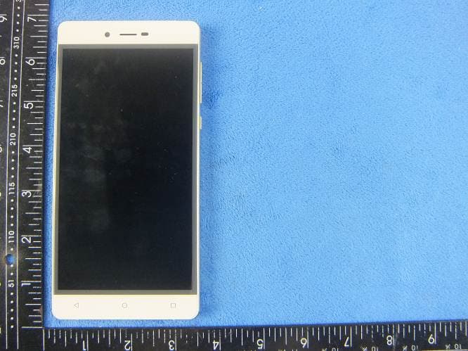
WA6SL6010
Nov 26, 2015Mobile Phone
Equipment Class
DTS - Digital Transmission System