WBKMBSC0700040RUThe Remote Unit on BTI DAS system
BTI Wireless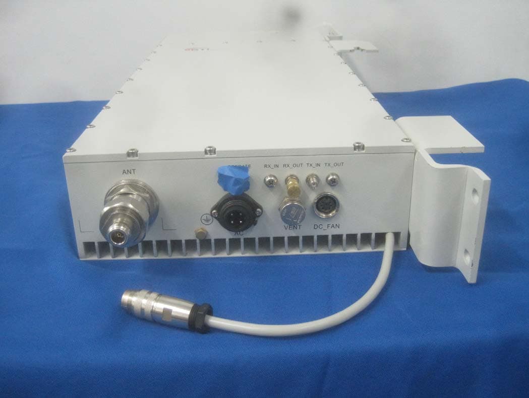
Click to zoom
Application Details
- Equipment Class
- B2I - Part 20 Industrial Booster (CMRS)
- Date of Grant
- Sep 25, 2014
- Application Purpose
- Original Equipment
- Date of Application
- Sep 27, 2013
- Equipment Note
- The Remote Unit on BTI DAS system
- Frequency Range
- 728.90000000 - 745.10000000
- Company
- BTI Wireless
- Country
- United States
Documents & Files
Document Text
Text extracted from the exhibit documents filed with the FCC. Open a document above to read the original.
Users Manual
Document Name: MBSC0700-040-RU Revision: 001.01A Effective Date: 4/15/2013 USER MANUAL Fiber Optic DAS Platform MBSC0700-040-RU High-Power In-Building Coverage Solution 6185 Phyllis Drive Cypress, CA 90630 USA PH: 714.230.8333 Visit our Website at www.BTIwireless.com MBSC0700-040-RU BTI Wireless 6185 Phyllis Drive Unit D, Cypress, CA 90630 Phone: 1-714-230-8333 Website: www.btiwireless.com MBSC0700-040-RU Copyright © 2013 BTI Wireless All rights reserved. No part of this publication may be reproduced, transmitted, transcribed, stored in a retrieval system, or translated into any language, in any form or by any means, electronic, mechanical, photocopying, recording, or otherwise, without prior written permission from BTI Wireless. All copyright, confidential information, patents, design rights and all other intellectual property rights of whatsoever nature contained herein are and shall remain the sole and exclusive property of BTI Wireless. The information furnished herein is believed to be accurate and reliable. However, no responsibility is assumed by BTI Wireless for its use, or for any infringements of patents or other rights of third parties resulting from its use. The BTI Wireless name and BTI Wireless logo are trademarks or registered trademarks of BTI Wireless All other trademarks are the property of their respective owners MBSC0700-040-RU ©1999-2013 Bravo Tech Inc. Document History Paper copies are valid only on the day they are printed. Contact the author if you are in any doubt about the accuracy of this document. Revision History Revision Number Revision Date Summary of Changes 001.00A 2/28/2013 Initial Release for NA 001.01A 4/15/2013 Updated for new EMS GENERAL SAFETY PRECAUTIONS Warning: Wet conditions increase the potential for receiving an electrical shock when installing or using electrically-powered equipment. To prevent electrical shock, never install or use electrical equipment in a wet location or during a lighting storm. Improper installation and operation of this equipment outside of the recommended installation procedures, and operation beyond the designed operating specifications, and/or not in compliance with regulatory requirements, will revoke any warranty and may: Prevent the equipment from performing properly Violate regulatory RF emissions requirements Require removal of the equipment from service. MBSC0700-040-RU ©1999-2013 Bravo Tech Inc. TABLE OF CONTENTS 1 INTRODUCTION 1 1.1 SYSTEM SOLUTION BLOCK DIAGRAM 1 1.1.1 Host Unit 1 1.1.2 Remote Node 2 2 SAFETY 3 3 SYSTEM OVERVIEW AND UNIT DESCRIPTION 4 3.1 SYSTEM OVERVIEW 4 3.1.1 Interface with BTS 4 3.1.2 Interface with Cellular Phones 5 3.1.3 Fiber Optic Transport 5 3.1.4 Powering 5 3.1.5 Cooling 5 3.1.6 Fault Detection and Alarm Reporting 5 3.2 HOST UNIT DESCRIPTION 6 3.2.1 Host Unit Components 6 3.2.2 Mounting 9 3.2.3 Fault Detection and Alarm Reporting 9 3.2.4 RF Signal Connections 9 3.2.5 Optical Connections 9 3.2.6 Powering 10 3.2.7 Host Unit Interface 10 3.3 REMOTE NODE DESCRIPTION 12 3.3.1 CM-BTS/ANT Enclosure 12 3.3.2 Single-band RUEnclosure 17 3.3.3 Power Supply Junction Box 20 3.3.4 Shroud& Bracket 21 4 SYSTEM INSTALLATION 23 4.1 UNPACKING AND INSPECTION 23 4.2 INSTALLATION PREPARATION 23 4.2.1 Required Tools 23 4.2.2 Installation Location 23 4.2.3 Anti-corrosion and Shock-protection 24 4.2.4 Lighting, Ventilation and Fire Protection 24 4.2.5 Power Requirements 24 MBSC0700-040-RU ©1999-2013 Bravo Tech Inc. 4.2.6 Lightning Protecting and Grounding 24 4.3 HOST UNIT INSTALLATION 24 4.3.1 Rack Mounting 24 4.3.2 Cable Connections 26 4.4 REMOTE NODE INSTALLATION 30 4.4.1 Bracket and Shroud Installation 30 4.4.2 Cable Connections 33 4.5 INSTALLATION FINAL INSPECTION 38 4.5.1 Host Unit Connection Overview 39 4.5.2 Remote Node Connection Overview 40 4.5.3 mBSC-C Inspection Checklist 41 4.5.4 Cabling Inspection 41 4.6 SYSTEM TEST 41 5 SYSTEM MONITORING &CONFIGURATION 43 5.1 ACCESSING EMS LOCAL GUI 43 5.1.1 Using Ethernet Port 43 5.1.2 Using USB Port 44 5.1.3 Login to EMS Local GUI 45 5.2 NAV I G AT I N G T H E EMS LOCAL GUI 46 5.2.1 Topology Tool Bar 47 5.2.2 Upgrade/Password Functions 48 5.3 INSTALLATION & CONFIGURATION 48 5.3.1 Network & Communications 48 5.3.2 System Installation 50 5.3.3 Alarms 55 5.4 SYSTEM TUNING 57 5.4.1 BTS Signal Conditioning 57 5.4.2 Set Downlink Gain 57 5.4.3 Set Uplink Gain 60 5.4.4 Link Verification 61 5.5 MONITORING AND ALARMS 63 5.5.1 Operational Status 63 5.5.2 System Alarms 65 5.6 SYSTEM UPGRADE 66 5.6.1 Verify Software Versions 66 5.6.2 Upgrade component software 66 MBSC0700-040-RU ©1999-2013 Bravo Tech Inc. 6 MAINTENANCE 67 6.1 ELECTROSTATIC DISCHARGE PRECAUTIONS 67 6.2 PREVENTATIVEMAINTENANCE 67 6.3 FAULT DETECTION AND ALARM REPORTING 67 6.4 TROUBLESHOOTING QUICK GUIDE 68 6.4.1 Host Unit Trouble Shooting 69 6.4.2 Remote Unit Trouble Shooting 70 7 TERMS, ACRONYMS & ABBREVIATIONS 71 MBSC0700-040-RU ©1999-2013 Bravo Tech Inc. LIST OF FIGURES FIGURE 1BLOCK DIAGRAM OF HOST UNIT ................................................................................................................................. 1 FIGURE 2 BLOCK DIAGRAM OF REMOTE NODE .......................................................................................................................... 2 FIGURE 3MBSC SYSTEM FUNCTIONAL OVERVIEW ..................................................................................................................... 4 FIGURE 4 HOST UNIT .................................................................................................................................................................. 6 FIGURE 5BIU ............................................................................................................................................................................. 7 FIGURE 6FIU .............................................................................................................................................................................…
Text truncated - open the document above for the full version.
Users Manual
Document Name: MBSC0700-040-RU Revision: 001.01A Effective Date: 4/15/2013 USER MANUAL Fiber Optic DAS Platform MBSC0700-040-RU High-Power In-Building Coverage Solution 6185 Phyllis Drive Cypress, CA 90630 USA PH: 714.230.8333 Visit our Website at www.BTIwireless.com MBSC0700-040-RU BTI Wireless 6185 Phyllis Drive Unit D, Cypress, CA 90630 Phone: 1-714-230-8333 Website: www.btiwireless.com MBSC0700-040-RU Copyright © 2014 BTI Wireless All rights reserved. No part of this publication may be reproduced, transmitted, transcribed, stored in a retrieval system, or translated into any language, in any form or by any means, electronic, mechanical, photocopying, recording, or otherwise, without prior written permission from BTI Wireless. All copyright, confidential information, patents, design rights and all other intellectual property rights of whatsoever nature contained herein are and shall remain the sole and exclusive property of BTI Wireless. The information furnished herein is believed to be accurate and reliable. However, no responsibility is assumed by BTI Wireless for its use, or for any infringements of patents or other rights of third parties resulting from its use. The BTI Wireless name and BTI Wireless logo are trademarks or registered trademarks of BTI Wireless All other trademarks are the property of their respective owners MBSC0700-040-RU ©1999-2013 Bravo Tech Inc. Document History Paper copies are valid only on the day they are printed. Contact the author if you are in any doubt about the accuracy of this document. Revision History Revision Number Revision Date Summary of Changes 001.00A 2/28/2013 Initial Release for NA 001.01A 4/15/2013 Updated for new EMS GENERAL SAFETY PRECAUTIONS Warning: Wet conditions increase the potential for receiving an electrical shock when installing or using electrically-powered equipment. To prevent electrical shock, never install or use electrical equipment in a wet location or during a lighting storm. Warning : This is NOT a CONSUMER device. It is designed for installation by FCC LICENSEES and QUALIFIED INSTALLERS. You MUST have an FCC LICENSE or express consent of an FCC License to operate this device. Unauthorized use may result in significant forfeiture penalties, including penalties in excess of $100,000 for each continuing violation. Improper installation and operation of this equipment outside of the recommended installation procedures, and operation beyond the designed operating specifications, and/or not in compliance with regulatory requirements, will revoke any warranty and may: Prevent the equipment from performing properly Violate regulatory RF emissions requirements Require removal of the equipment from service. MBSC0700-040-RU ©1999-2013 Bravo Tech Inc. TABLE OF CONTENTS 1 INTRODUCTION 1 1.1 SYSTEM SOLUTION BLOCK DIAGRAM 1 1.1.1 Host Unit 1 1.1.2 Remote Node 2 2 SAFETY 3 3 SYSTEM OVERVIEW AND UNIT DESCRIPTION 4 3.1 SYSTEM OVERVIEW 4 3.1.1 Interface with BTS 4 3.1.2 Interface with Cellular Phones 5 3.1.3 Fiber Optic Transport 5 3.1.4 Powering 5 3.1.5 Cooling 5 3.1.6 Fault Detection and Alarm Reporting 5 3.2 HOST UNIT DESCRIPTION 6 3.2.1 Host Unit Components 6 3.2.2 Mounting 9 3.2.3 Fault Detection and Alarm Reporting 9 3.2.4 RF Signal Connections 9 3.2.5 Optical Connections 9 3.2.6 Powering 10 3.2.7 Host Unit Interface 10 3.3 REMOTE NODE DESCRIPTION 12 3.3.1 CM-BTS/ANT Enclosure 12 3.3.2 Single-band RUEnclosure 17 3.3.3 Power Supply Junction Box 20 3.3.4 Shroud& Bracket 21 4 SYSTEM INSTALLATION 23 4.1 UNPACKING AND INSPECTION 23 4.2 INSTALLATION PREPARATION 23 4.2.1 Required Tools 23 4.2.2 Installation Location 23 4.2.3 Anti-corrosion and Shock-protection 24 4.2.4 Lighting, Ventilation and Fire Protection 24 4.2.5 Power Requirements 24 MBSC0700-040-RU ©1999-2013 Bravo Tech Inc. 4.2.6 Lightning Protecting and Grounding 24 4.3 HOST UNIT INSTALLATION 24 4.3.1 Rack Mounting 24 4.3.2 Cable Connections 26 4.4 REMOTE NODE INSTALLATION 30 4.4.1 Bracket and Shroud Installation 30 4.4.2 Cable Connections 33 4.5 INSTALLATION FINAL INSPECTION 38 4.5.1 Host Unit Connection Overview 39 4.5.2 Remote Node Connection Overview 40 4.5.3 mBSC-C Inspection Checklist 41 4.5.4 Cabling Inspection 41 4.6 SYSTEM TEST 41 5 SYSTEM MONITORING &CONFIGURATION 43 5.1 ACCESSING EMS LOCAL GUI 43 5.1.1 Using Ethernet Port 43 5.1.2 Using USB Port 44 5.1.3 Login to EMS Local GUI 45 5.2 NAV I G AT I N G T H E EMS LOCAL GUI 46 5.2.1 Topology Tool Bar 47 5.2.2 Upgrade/Password Functions 48 5.3 INSTALLATION & CONFIGURATION 48 5.3.1 Network & Communications 48 5.3.2 System Installation 50 5.3.3 Alarms 55 5.4 SYSTEM TUNING 57 5.4.1 BTS Signal Conditioning 57 5.4.2 Set Downlink Gain 57 5.4.3 Set Uplink Gain 60 5.4.4 Link Verification 61 5.5 MONITORING AND ALARMS 63 5.5.1 Operational Status 63 5.5.2 System Alarms 65 5.6 SYSTEM UPGRADE 66 5.6.1 Verify Software Versions 66 5.6.2 Upgrade component software 66 MBSC0700-040-RU ©1999-2013 Bravo Tech Inc. 6 MAINTENANCE 67 6.1 ELECTROSTATIC DISCHARGE PRECAUTIONS 67 6.2 PREVENTATIVEMAINTENANCE 67 6.3 FAULT DETECTION AND ALARM REPORTING 67 6.4 TROUBLESHOOTING QUICK GUIDE 68 6.4.1 Host Unit Trouble Shooting 69 6.4.2 Remote Unit Trouble Shooting 70 7 TERMS, ACRONYMS & ABBREVIATIONS 71 MBSC0700-040-RU ©1999-2013 Bravo Tech Inc. LIST OF FIGURES FIGURE 1BLOCK DIAGRAM OF HOST UNIT ................................................................................................................................. 1 FIGURE 2 BLOCK DIAGRAM OF REMOTE NODE .......................................................................................................................... 2 FIGURE 3MBSC SYSTEM FUNCTIONAL OVERVIEW ..................................................................................................................... 4 FIGURE 4 HOST UNIT .................................................................................................................................................................. 6 FIGURE 5BIU .................…
Text truncated - open the document above for the full version.
Users Manual
Document Name: MBSC0700-040-RU Revision: 001.01A Effective Date: 4/15/2013 USER MANUAL Fiber Optic DAS Platform MBSC0700-040-RU High-Power In-Building Coverage Solution 6185 Phyllis Drive Cypress, CA 90630 USA PH: 714.230.8333 Visit our Website at www.BTIwireless.com MBSC0700-040-RU BTI Wireless 6185 Phyllis Drive Unit D, Cypress, CA 90630 Phone: 1-714-230-8333 Website: www.btiwireless.com MBSC0700-040-RU Copyright © 2014 BTI Wireless All rights reserved. No part of this publication may be reproduced, transmitted, transcribed, stored in a retrieval system, or translated into any language, in any form or by any means, electronic, mechanical, photocopying, recording, or otherwise, without prior written permission from BTI Wireless. All copyright, confidential information, patents, design rights and all other intellectual property rights of whatsoever nature contained herein are and shall remain the sole and exclusive property of BTI Wireless. The information furnished herein is believed to be accurate and reliable. However, no responsibility is assumed by BTI Wireless for its use, or for any infringements of patents or other rights of third parties resulting from its use. The BTI Wireless name and BTI Wireless logo are trademarks or registered trademarks of BTI Wireless All other trademarks are the property of their respective owners MBSC0700-040-RU ©1999-2013 Bravo Tech Inc. Document History Paper copies are valid only on the day they are printed. Contact the author if you are in any doubt about the accuracy of this document. Revision History Revision Number Revision Date Summary of Changes 001.00A 2/28/2013 Initial Release for NA 001.01A 4/15/2013 Updated for new EMS GENERAL SAFETY PRECAUTIONS Warning: Wet conditions increase the potential for receiving an electrical shock when installing or using electrically-powered equipment. To prevent electrical shock, never install or use electrical equipment in a wet location or during a lighting storm. Warning : This is NOT a CONSUMER device. It is designed for installation by FCC LICENSEES and QUALIFIED INSTALLERS. You MUST have an FCC LICENSE or express consent of an FCC License to operate this device. Unauthorized use may result in significant forfeiture penalties, including penalties in excess of $100,000 for each continuing violation. Improper installation and operation of this equipment outside of the recommended installation procedures, and operation beyond the designed operating specifications, and/or not in compliance with regulatory requirements, will revoke any warranty and may: Prevent the equipment from performing properly Violate regulatory RF emissions requirements Require removal of the equipment from service. MBSC0700-040-RU ©1999-2013 Bravo Tech Inc. TABLE OF CONTENTS 1 INTRODUCTION 1 1.1 SYSTEM SOLUTION BLOCK DIAGRAM 1 1.1.1 Host Unit 1 1.1.2 Remote Node 2 2 SAFETY 3 3 SYSTEM OVERVIEW AND UNIT DESCRIPTION 4 3.1 SYSTEM OVERVIEW 4 3.1.1 Interface with BTS 4 3.1.2 Interface with Cellular Phones 5 3.1.3 Fiber Optic Transport 5 3.1.4 Powering 5 3.1.5 Cooling 5 3.1.6 Fault Detection and Alarm Reporting 5 3.2 HOST UNIT DESCRIPTION 6 3.2.1 Host Unit Components 6 3.2.2 Mounting 9 3.2.3 Fault Detection and Alarm Reporting 9 3.2.4 RF Signal Connections 9 3.2.5 Optical Connections 9 3.2.6 Powering 10 3.2.7 Host Unit Interface 10 3.3 REMOTE NODE DESCRIPTION 12 3.3.1 CM-BTS/ANT Enclosure 12 3.3.2 Single-band RUEnclosure 17 3.3.3 Power Supply Junction Box 20 3.3.4 Shroud& Bracket 21 4 SYSTEM INSTALLATION 23 4.1 UNPACKING AND INSPECTION 23 4.2 INSTALLATION PREPARATION 23 4.2.1 Required Tools 23 4.2.2 Installation Location 23 4.2.3 Anti-corrosion and Shock-protection 24 4.2.4 Lighting, Ventilation and Fire Protection 24 4.2.5 Power Requirements 24 MBSC0700-040-RU ©1999-2013 Bravo Tech Inc. 4.2.6 Lightning Protecting and Grounding 24 4.3 HOST UNIT INSTALLATION 24 4.3.1 Rack Mounting 24 4.3.2 Cable Connections 26 4.4 REMOTE NODE INSTALLATION 30 4.4.1 Bracket and Shroud Installation 30 4.4.2 Cable Connections 33 4.5 INSTALLATION FINAL INSPECTION 38 4.5.1 Host Unit Connection Overview 39 4.5.2 Remote Node Connection Overview 40 4.5.3 mBSC-C Inspection Checklist 41 4.5.4 Cabling Inspection 41 4.6 SYSTEM TEST 41 5 SYSTEM MONITORING &CONFIGURATION 43 5.1 ACCESSING EMS LOCAL GUI 43 5.1.1 Using Ethernet Port 43 5.1.2 Using USB Port 44 5.1.3 Login to EMS Local GUI 45 5.2 NAV I G AT I N G T H E EMS LOCAL GUI 46 5.2.1 Topology Tool Bar 47 5.2.2 Upgrade/Password Functions 48 5.3 INSTALLATION & CONFIGURATION 48 5.3.1 Network & Communications 48 5.3.2 System Installation 50 5.3.3 Alarms 55 5.4 SYSTEM TUNING 57 5.4.1 BTS Signal Conditioning 57 5.4.2 Set Downlink Gain 57 5.4.3 Set Uplink Gain 60 5.4.4 Link Verification 61 5.5 MONITORING AND ALARMS 63 5.5.1 Operational Status 63 5.5.2 System Alarms 65 5.6 SYSTEM UPGRADE 66 5.6.1 Verify Software Versions 66 5.6.2 Upgrade component software 66 MBSC0700-040-RU ©1999-2013 Bravo Tech Inc. 6 MAINTENANCE 67 6.1 ELECTROSTATIC DISCHARGE PRECAUTIONS 67 6.2 PREVENTATIVEMAINTENANCE 67 6.3 FAULT DETECTION AND ALARM REPORTING 67 6.4 TROUBLESHOOTING QUICK GUIDE 68 6.4.1 Host Unit Trouble Shooting 69 6.4.2 Remote Unit Trouble Shooting 70 7 TERMS, ACRONYMS & ABBREVIATIONS 71 MBSC0700-040-RU ©1999-2013 Bravo Tech Inc. LIST OF FIGURES FIGURE 1BLOCK DIAGRAM OF HOST UNIT ................................................................................................................................. 1 FIGURE 2 BLOCK DIAGRAM OF REMOTE NODE .......................................................................................................................... 2 FIGURE 3MBSC SYSTEM FUNCTIONAL OVERVIEW ..................................................................................................................... 4 FIGURE 4 HOST UNIT .................................................................................................................................................................. 6 FIGURE 5BIU .................…
Text truncated - open the document above for the full version.
Cover Letter(s)
BTIWIRELESSTM 8/19/2013 FederalCommunicationsCommission 7435OaklandMillsRoad Columbia,MD21046 Subject:RequestforPermanentConfidentiality Towhomitmayconcern: Inaccordancewith47CFRSection0.457andSection0.459pertainingtoconfidentialmaterial,wehereby requesttoholdpermanentlyconfidentialallinformationcontainedwithinthebelowidentified exhibits/documentcategoriessubmittedpursuanttoradioequipmentcertificationrequirementsforFCCID: WBKMBSCO70004ORU 1.BlockDiagram 2.OperationalDescription 3.Schematics 4.PartsList/Tune-UpProcedure Theabovematerialcontainstradesecretsandproprietaryinformationasspecifiedby47CFR0.457(d)and technicaldata,whichwouldcustomarilybeguardedfromcompetitors.Thepublicdisclosureofthis informationmightbeharmfultoourcompanyandprovideunjustifiedbenefitstoourcompetitors. Sincerely, ~HEN~ COO BTIWireless 6185PhyHisDr.,UnitD,Cypress,CA90630ITel:+1714-230-8333Fax:+1714-230-8341www.btiwireless.com
Cover Letter(s)
During application upload, the internal photos were mistakenly uploaded under exhibit type “External Photos” The internal photos were uploaded again under the correct exhibit type. Please supersede the “internal photos” currently displayed under the external photos exhibit type. -CKC Certification Services, LLC.
Cover Letter(s)
# Request Response 1 Unless it is in there already, please revise external photos or label exhibits to show placement/location of FCC ID label and 20.21(f) label on the device. Updated exhibit provided 1/10/14 2 Please submit RF exposure compliance supporting information [KDB pub 447498, KDB pub 865664, KDB pub 935210, FCC-13-21 para. 181, etc.]. This equipment is not sold with an antenna; it is a fixed station and thus RF exposure is to be addressed at the time of licensing for the station. 3 Further to 20.21(f)(1)(2), the 20.21(f)(1)(4)(ii) statement is needed in the install/operating instructions too; if not in there already then please revise. Updated exhibit provided 1/10/14 4 Install/operating instructions indicate G7D modulation, while f-731 has W7D. Please clarify one or the other (or both if applicable, then how), and basis for it based on the signal configurations tested. Updated exhibit provided 1/10/14. 5 Unless it is in the EMC/radio report already, please amend to address KDB pub 935210 D01 “part of system” operating / testing with host/master unit. In other words please amend with basic descriptions of host/master unit that can operate with this remote, signal types supplied by it, FCC equipment authorization status for it, etc. For example Fig2 of install/operate instructions indicates fiber-optic interface for RF-over-fiber. This device is a slave unit which does not operate with fiber optic input; but RF input only from a master device. Updated operational description provided 2/4/14 clarifying device operation. FYI related policy/procedures provisions include the following. KDB 935210 D01 v01r01, "... Where donor-side and server-side components (components B, C of Figure 3) are not electrically identical, each component generally is subject to separate / individual equipment authorization. For example, where a donor-side device never connects to an antenna for transmitting over-the-air, then only part 15 subpart B digital device authorization might apply. Donor-side and server-side components generally need to be tested together as a system, and equipment applications need to describe and address compliance for the supported signal and modulation types for each path. The Form-731 provision for “part of a system that operates with, or is marketed with, another device that requires an equipment authorization” needs to be completed as applicable, e.g., when the transport link uses proprietary signaling such that each donor or server component operates only with specific associated devices. ..." KDB 935210 D02 v01r01, 6) System operation – When transmitter requires other devices in a system, select Form 731 “Part of system...” checkbox. List FCC IDs of other components. Test with system components if needed. Usually applies for fiber-optic systems. Control of power level is one implication. 6 Unless it is in the filing already, please amend to explain/show compliance for the following. KDB 935210 D02 v01r01, 11) Output power – e) Devices using automatic gain control (AGC) for compliance with service rule power limits should provide test results showing maximum output with and without AGC activated. 13) Worst case results should be reported for occupied bandwidth comparison and intermodulation tests done with and without any AGC circuitry activated, for devices so equipped Per manufacturer declaration, the device does not employ AGC circuit, therefore requirements identified in e and 13 are not applicable. Our product has ALC function and it’s similar with AGC, but not same. Because our product has the fixed gain and only when the output reaches to the threshold, the output level is limited by ALC function
RF Exposure Info
Page 1 of 8 Report No: 94688-9 RADIO FREQUENCY EXPOSURE REPORT FOR THE Device: 700MHz 40W Remote Transmitting Unit Model: mBSC0700-040-RUC11 Report No.: 94688-9 Date of issue: June 16, 2014 PREPARED FOR: BTI Wireless 6185 Phyllis Drive. Unit D Cypress, CA 90630 PREPARED BY: Eddie Wong CKC Laboratories, Inc. 5046 Sierra Pines Drive Mariposa, CA 95338 The test data contained in this report documents the observed testing parameters pertaining to and are relevant for only the sample equipment tested in the agreed upon operational mode(s) and configuration(s) as identified herein. Compliance assessment remains the client’s responsibility. This report may not be used to claim product endorsement by A2LA or any government agencies. This test report has been authorized for release under quality control from CKC Laboratories, Inc. Steve Behm Director of Quality Assurance & Engineering Services CKC Laboratories, Inc. Page 2 of 8 Report No: 94688-9 Purpose: To demonstrate compliance with United States, Canada and/or European Union RF Exposure requirements for Portable equipment (devices used ≤20cm from the body) or Mobile equipment (devices used >20cm from the body) with power output below exemption levels and Mobile equipment, where Maximum Permissible Exposure (MPE) Calculations apply. United States Compliance Requirements (1.1310): RF Exposure Evaluation Limits Occupational / Controlled Exposure Frequency Range (MHz) Electric Field Strength (V/m) Magnetic Field Strength (A/m) Power Density (mW/cm 2 ) Averaging Time (minutes) 0.3-3.0 614 1.63 *(100) 6 3.0-30 1842/f 4.89/f *(900/f 2 ) 6 30-300 61.4 0.163 1 6 300-1500 --- --- f/300 6 1500-100,000 --- --- 5.0 6 RF Exposure Evaluation Limits General Population / Uncontrolled Exposure Frequency Range (MHz) Electric Field Strength (V/m) Magnetic Field Strength (A/m) Power Density (mW/cm 2 ) Averaging Time (minutes) 0.3-1.34 614 1.63 *(100) 30 1.34-30 824/f 2.19/f *(180/f 2 ) 30 30-300 27.5 0.073 0.2 30 300-1500 --- --- f/1500 30 1500-100,000 --- --- 1.0 30 * Plane wave equivalent power density Limit is calculated based on the mid-band frequency used in the operating frequency range. Exemption Level: Power output <60/f GHz (mW) Page 3 of 8 Report No: 94688-9 Canadian Compliance Requirements (RSS-102): RF Exposure Evaluation Limits Occupational / Controlled Exposure Frequency Range (MHz) Electric Field Strength (V/m) Magnetic Field Strength (A/m) Power Density (W/m 2 ) Averaging Time (minutes) 0.003-1.0 600 4.9 --- 6 1.0-10 600/f 4.9/f --- 6 10-30 60 4.9/f --- 6 30-300 60 0.163 10 6 300-1500 3.54 f 0.5 0.0094*f 0.5 f/3 6 1500-15,000 137 0.364 50 6 15,000-150,000 137 0.364 50 616000/f 1.2 RF Exposure Evaluation Limits General Population / Uncontrolled Exposure Frequency Range (MHz) Electric Field Strength (V/m) Magnetic Field Strength (A/m) Power Density (W/m 2 ) Averaging Time (minutes) 0.003-1.0 280 2.19 --- 6 1.0-10 280/f 2.19/f --- 6 10-30 28 2.19/f --- 6 30-300 28 0.073 2 6 300-1500 1.585 * f 0.5 0.0042 * f 0.5 f/150 6 1500-15,000 61.4 0.163 10 6 15,000-150,000 61.4 0.163 10 616000/f 1.2 *Power density limit applicable >100MHz Exemption Level: Frequency Range (MHz) Maximum Output Power (Conducted or EIRP) 0.003-1000 ≤ 200 mW 1000-2200 ≤ 100 mW 2200-3000 ≤ 20 mW 3000-6000 ≤ 10 mW Page 4 of 8 Report No: 94688-9 European Union Compliance Requirements (ICNIRP): RF Exposure Evaluation Limits Occupational / Controlled Exposure Frequency Range (MHz) Electric Field Strength (V/m) Magnetic Field Strength (A/m) Power Density (W/m 2 ) Averaging Time (minutes) 0.00082-0.065 610 24.4 --- 6 0.065-1.0 610 1.6/f --- 1.0-10 610/f 1.6/f --- 6 10-400 61 0.16 10 6 400-2000 3.0 * f 0.5 0.008 * f 0.5 f/40 6 2000-300,000 137 0.36 50 6 RF Exposure Evaluation Limits General Population / Uncontrolled Exposure Frequency Range (MHz) Electric Field Strength (V/m) Magnetic Field Strength (A/m) Power Density (W/m 2 ) Averaging Time (minutes) 0.003-0.150 87 5.0 --- 6 0.150-1.0 87 0.73/f -- 6 1.0-10 87/f 0.5 0.73/f --- 6 10-400 28 0.073 2 6 400-2000 1.375 f 0.5 0.0037*f 0.5 f/200 6 2000-300,000 61 0.16 10 6 *Power density limit applicable >100MHz Exemption Level: Power output < 20mW 1 1 May vary by product type Page 5 of 8 Report No: 94688-9 Device and Antenna Operating Configuration: Device operating at maximum output power with continuous transmission of modulated data. 15 MHz LTE modulation, maximum measured power at 737MHz, 39.72W 46dBm. Antenna = 16dBi. Test Procedure: This equipment is evaluated in accordance with the guidelines set forth in OET Guide 65 & ANSI C95.1 for the US and Health Canada Safety Code 6 & RSS 102 for Canada. Other Considerations: None Page 6 of 8 Report No: 94688-9 MPE Calculations Applicability: Limit Used X General Population / Uncontrolled Exposure Occupational / Controlled Exposure RF Exposure Exemption No United States NA Canada NA Europe Equipment operational details: Config # Operating Frequency (MHz) Measured Output Power (dBm) Antenna Gain (dBi) Antenna Type / Configuration EIRP (dBm) 1 737 46 16 NA 62 Measurements based from EMC Test Report(s): 94688-3 MPE Calculation: 2 4d EIRP DensityPower Given: EIRP in mW or W and d in cm or m Minimum Distance of Separation: Distance to meet these limits: Config Freq Range EIRP US # (mW) (cm) 1 728-745 1584893.19 507.338 Page 7 of 8 Report No: 94688-9 Summary Exemptions: In the case the equipment meets compliance requirements by exemption the product is approved for use under mobile or portable conditions without further testing under the condition that any additional collocation or simultaneous transmission requirements (including necessary separation distances) have been met. MPE Calculation Results: In the case the equipment meets compliance by MPE Calculations the product is approved for use under mobile conditions without further testing under the condition that any additional collocation or simultaneous transmission requirements (including necessary separation distances) have been met. It is assum…
Text truncated - open the document above for the full version.
Test Report
This report contains a total of 57 pages and may be reproduced in full only. Partial reproduction may only be done with the written consent of CKC Laboratories, Inc. BTI Wireless TEST REPORT FOR 700MHz 40W Remote Transmitting Unit Model: mBSC0700-040-RUC11 Tested To The Following Standard: FCC Part 27C Report No.: 94688-3 Date of issue: August 16, 2013 This test report bears the accreditation symbol indicating that the testing performed herein meets the test and reporting requirements of ISO/IEC 17025 under the applicable scope of EMC testing for CKC Laboratories, Inc. We strive to create long-term, trust based relationships by providing sound, adaptive, customer first testing services. We embrace each of our customers’ unique EMC challenges, not as an interruption to set processes, but rather as the reason we are in business. Page 2 of 57 Report No.: 94688-3 TABLE OF CONTENTS Administrative Information .......................................................................................................................... 3 Test Report Information ........................…
Text truncated - open the document above for the full version.
Contact Information
Applicant
Gang Liang(VP of Business Development)
Technical Contact
BTI WirelessRaymond Shin
[email protected]714-230-8333
6185 Phyllis Drive · Cypress, California · United States
Test Firm
CKC Laboratories, Inc.Steve Behm
Technical Specifications
| # | Rule Parts | Frequency Range | Power Output | Emission | Tolerance |
|---|---|---|---|---|---|
| 3 | 27 | 728.9 MHz - 745.1 MHz | 10.12 W | W7D | Amp |
Other Applications from BTI Wireless
WBKRU446078
Apr 21, 2026Remote Radio Unit
Equipment Class
TNB - Licensed Non-Broadcast Station Transmitter
WBK-RU243171
Feb 10, 2026Remote Radio Unit
Equipment Class
TNB - Licensed Non-Broadcast Station Transmitter
WBK-RU437041
Jun 12, 20245G Integrated Base Station
Equipment Class
TNT - Licensed Non-Broadcast Transmitter Worn on BodyWBKF224041
Apr 10, 20245G NR Femtocell
Equipment Class
TNT - Licensed Non-Broadcast Transmitter Worn on Body
WBK-RU4370
Apr 03, 2023Remote Radio Unit
Equipment Class
CBD - Citizens Band Category A and B Devices