WC2DS-1108PORTABLE WIRELESS SPEAKER
Wonders Technology Co., Ltd.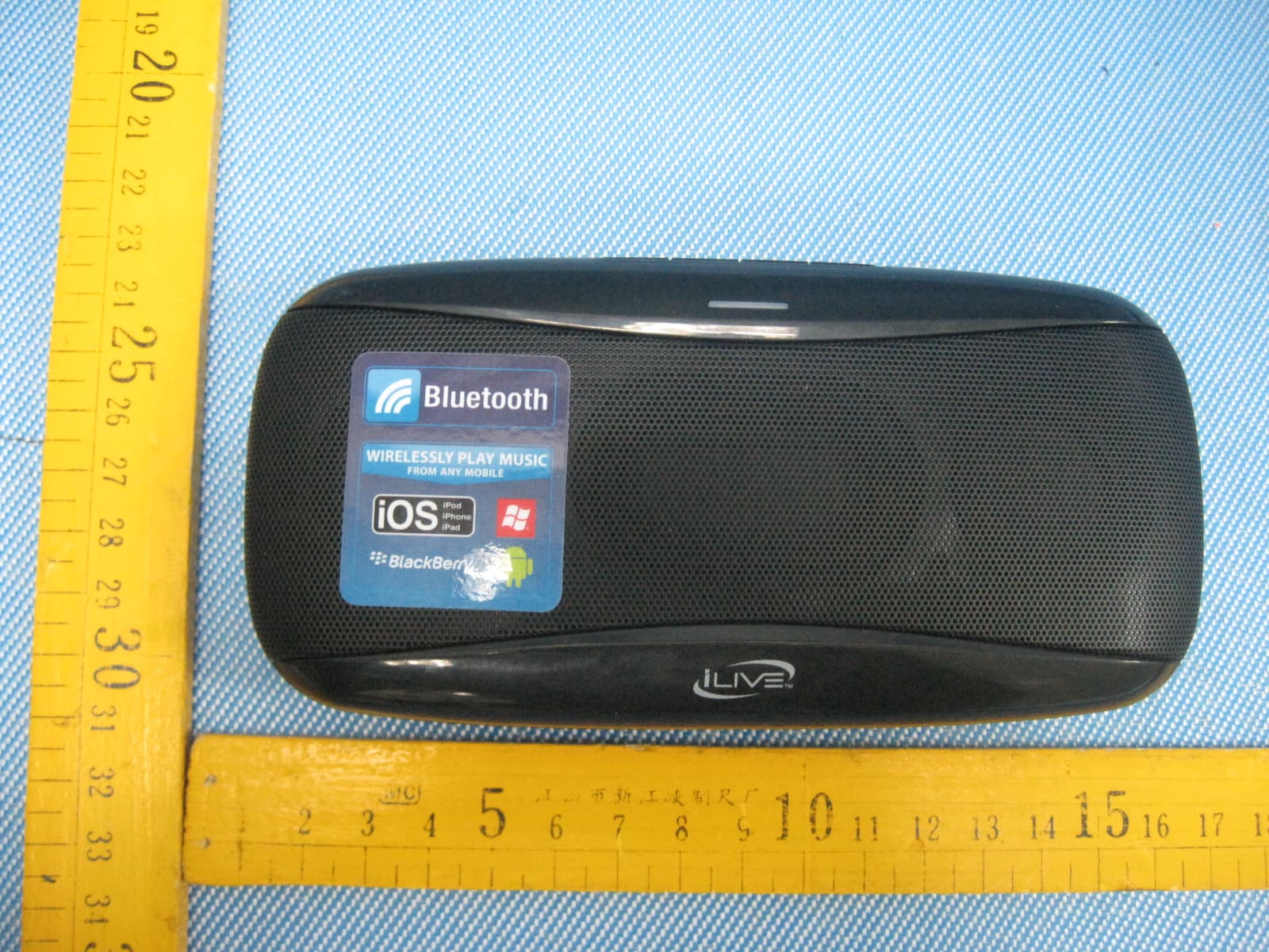
Click to zoom
Application Details
- Equipment Class
- DSS - Part 15 Spread Spectrum Transmitter
- Date of Grant
- Sep 04, 2012
- Application Purpose
- Original Equipment
- Date of Application
- Sep 04, 2012
- Equipment Note
- PORTABLE WIRELESS SPEAKER
- Frequency Range
- 2402.00000000 - 2480.00000000
- Company
- Wonders Technology Co., Ltd.
- Country
- China
Documents & Files
Document Text
Text extracted from the exhibit documents filed with the FCC. Open a document above to read the original.
Users Manual
Warranty Contact Information For Warranty Information and the most up-to-date version of this User’s Guide, go to: www.iLiveElectronics.com Email Support: [email protected] Email Parts: [email protected] Phone Support: 1-888-999-4215 Website: www.iLiveElectronics.com Warnings and Precautions • WARNING: To prevent fire or shock hazards, do not expose this unit to rain or moisture. • WARNING: Do not place the unit on top of any soft, porous, or sensitive surfaces to avoid damaging the surface. Use a protective barrier between the unit and surface to protect the surface. • WARNING : Where the mains plug or appliance coupler is used as the disconnect device, such disconnect device shall remain readily operable. • Note : This device uses an internal rechargeable lithium-ion battery that should last the lifetime of the device. If you suspect your battery may be dead after several attempts to charge, please contact 1-888-999-4215 for support. • Never disassemble the unit or attempt to remove the battery as that could cause leakage of an electrolytic substance. Warning: Changes or modifications to this unit not expressly approved by the party responsible for compliance could void the user’s authority to operate the equipment. FCC NOTE: This device complies with Part 15 of the FCC Rules. Operation is subject to the follow:(1) This device may not cause harmful interference, and (2) This device must accept any including interference that may cause undesired operation. The manufacturer is not responsible for any radio or TV interference caused by uncouth. Such modifications could void the user's authority to operate the equipment. • • • • FCC Warnings Pairing a Bluetooth Device 1. Turn on the unit using the On/Off switch. The Pairing Indicator will flash blue quickly. 2. Press and hold the Pair button until a beep sounds. When pairing, remain within 3 feet of the unit. 3. Using the native controls on your Bluetooth device, select the “DS-1108” in your Bluetooth settings to pair. If your device requests a password, enter the default password “ 0 0 0 0 ”. Refer to the user’s manual for your specific device for instructions on pairing and connecting Bluetooth devices. 4. When successfully paired and connected, the Pairing Indicator will display a solid blue light and a beep will sound from the unit. After initial pairing, the unit will stay paired unless unpaired manually by the user. Playing Audio Wirelessly 1. Follow the instructions for Pairing a Bluetooth Device. 2. Use the native controls on the connected Bluetooth device to select a track. 3. To play, pause or skip the selected track, use the native controls on the connected Bluetooth device or press the Play/Pause button on the unit. 4. Audio played through the connected Bluetooth device will now be heard through the speakers. 5. Press and hold the Vol+/Vol- buttons to adjust the volume. Using the Line Input 1. Plug one end of a 3.5 mm audio input cable (not included) into the Line Input on the unit. 2. Plug the other end of the cable into the audio output/ headphone output on an MP3 Player or other audio source. 3. Turn on the unit using the On/Off switch. 4. Audio played through the connected device will now be heard through the speakers. Note: Any audio being played through a connected Bluetooth Device will cease once the 3.5mm Audio source is connected. USER’S GUIDE V: 712-01 For the most up-to-date version of this User’s Guide, go to www.iLiveElectronics.com ISB182 Portable Wireless Speaker To download this User’s Guide in English, Spanish, or French, or to get answers to frequently asked questions, visit the support section at www.iLiveElectronics.com Para descargar este Manual del Usuario en inglés, español y francés, o para obtener respuestas a preguntas frecuentes, visite la sección de apoyo en www. iLiveElectronics.com Pour télécharger ce guide de l’utilisateur en anglais, espagnol ou français, ou pour obtenir des réponses à des questions fréquemment posées, consultez la rubrique d’assistance sur www.iLiveElectronics.com International Support Features • Supports profile A2DP (Advanced Audio Distribution Profile) • Built-in speakers • 3.5mm audio input • Micro-USB port for bat- tery recharge • LED pairing indicator • Low battery indicator • DC battery power: built-in rechargeable lithium ion battery • Metal speaker grill Included • Micro USB to USB charging cable Power USB Power Requires a Micro USB to USB cable (included). During initial charge please continue to charge the unit for at least 2 hours after the battery indicator light has turned green. Note: PC must not be in sleep mode. CHARGE BATTERY STATUS Status Indicator Power OffNo light ChargingRed light Fully ChargedGreen light Low batteryFlashing red light Introduction PAIR Pair Press and hold to begin connecting a Bluetooth device. Volume Press and hold to increase or decrease the volume. Play/Pause Press to play or pause. Pairing Indicator CHARGE BATTERY STATUS On/Off Adjust the switch to turn the unit on or off. Always be sure to switch to the OFF position when not in use. Stand Introduction CHARGE BATTERY STATUS Line Input Micro USB Charging Port (Charging only) Low Battery Indicator Stand Introduction
Block Diagram
1 2 3 4 5 6 78 ABCD 8 7 6 5 4 3 2 1 D CBA AUX OP-AMP U2(358) POWER AMP U1(HT6809) VCC VCC BLOCK DIAGRAM MODEL: DATE: 2012.08.10 REV: 1.0 BLUETOOTH ANTENNA MODULE STATE DISPLAY BLUETOOTH OVC3860/24C08C BLUETOOTH POWER RECHARGE DC5V IN MANAGEMENT 3.7V LITHIUM BATTERY RECHARGE DISPLAY IC1(EMC5754) BUTTON CONTEROL POWER SWITCH VCC F-3089 Balun and filter ANT matching EEPROM Audio Codec Power control and regulation Crystal 12MHz OVC3860/24C08C
External Photos
2.1 EUT – Appearance View
ID Label/Location Info
Page:61 of 61 Wonders Technology Co., Ltd. FCC ID: WC2DS-1108 The results shown in this test report refer only to the sample(s) tested , This Test report cannot be reproduced, except in full, without prior written permission of the Company. WALTEK SERVICES Reference No.: WT12085548-D-S-F 17 FCC Label This device complies with Part 15 of the FCC Rules. Operation is subject to the following two conditions:(1)this device may not cause harmful interference,and (2) this device must accept any interference received, including interference that may cause undesired operation. The Label must not be a stick-on paper. The Label on these products must be permanently affixed to the product and readily visible at the time of purchase and must last the expected lifetime of the equipment not be readily detachable. Proposed Label Location on EUT EUT Back View/ proposed FCC Label Location FCC ID: WC2DS-1108 This device complies with Part 15 of the FCC Rules. Operation is subject to the following two conditions: (1) this device may not cause harmful interference, and (2) this device must accept any interference received, including interference that may cause undesired operation.
ID Label/Location Info
FCC ID Label Sample for Models: DS-1108, ISB182B FCC ID: WC2DS-1108 This device complies with Part 15 of the FCC Rules. Operation is subject to the following two conditions: (1) this device may not cause harmful interference, and (2) this device must accept any interference received, including interference that may cause undesired operation.
Internal Photos
2.1 EUT- Open View 2.2 EUT – PCB View
Operational Description
Power Supply: DC 3.7V Speaker Impedance: 4Ohm DS-1108 is a Bluetooth speaker, introductions for the circuits: AUX signal was sent through the JACK2 (earphone socket) to U1 (HT6809) the amplifier U1 (HT6809), and finally to the speaker. Under Bluetooth status, Pls press ‘pair ’button at the back of the speaker to pair with the external BT equipment. After paired, it will play the music. The signal is conducted after the Bluetooth receiver module to the COMMON Mode U2 (LM358), via amplifier U1 (HT6809), and finally to the speaker. When play the music, we can press PLAY/PAUSE and volume up and down buttons.U2 (LM358) is the pre-amplifier. SW4 (PAIR button) 、SW3(Volume down)、SW2(PLAY/PAUSE)、SW1(Volume up)、LED1(charging indicator)、 LED2(AUX/Bluetooth status indicator). The device is a bluetooth stereo speaker, The working frequency of RF module F-3089(crystal is 12MHz) is setted to 2402MHz ~ 2480MHz, the frequency separation is 1MHz and there are 79 channels. with the spread spectrum code sequences to hopping constantly. To make sure the communication stable, Bluetooth special design the fast acknowledge and frequency hopping plan to ensure that link stability. First link, between Bluetooth devices will build a pseudorandom code, Only the pseudorandom code is same, the information transfer will be accepted. Other interference is not possible in the same sequence of interference. Bluetooth through the spread spectrum technology, Make the influence of interference may become very small. The working procedures are: 1. Power on, the indicator light flashes faster, the DS-1108 enter to pair mode.The DS-1108 will do the frequency hopping according to a certain sequence, and then send the connection command. 2. If there is a Device response, the DS-1108 will judge whether it can be permitted to connect. Prompt enter a passkey. 3. If the passkey is right, then can be permitted to connect, send the connection command to build up the connection. 4. While the connection build up successfully, the data transmission is beginning. At the same time, the DS-1108 and device will shift frequencies in synchronization per a same pseudo randomly ordered list of hopping frequencies, the hopping rate is 1600 times per second. 5. The bandwidth of the receiver, which is set to a fix width by the software, match the hopping channel bandwidth of their corresponding transmitte
Schematics
1 2 3 4 5 6 78 ABCD 8 7 6 5 4 3 2 1 D CBA 12345 J2 R341KR37 1K R36 33K R3533K C41 105 C42 105 VCC C8 225 C9 225 R13 10K R15 10K C16563 C14563 C13 105 R6 1M C18 563 C17 563 C31 224 C28 224 C30 224 C32 224 1 23 + - U2A LM358 7 65 + - U2BLM358 8 4 U2C LM358 R23 22K R24 22K R21 22K R22 22K R16 30K R17 30K C19224C20224 R19 22K R20 22K R18 36K R44 22K C26 104 R91K 1 2 3 4 5 VOL+ 1 VOL- 2 UP 3 DOWN 4 PLAY/PU 5 1.8V 6 GND 7 VDD 8 LED1 9 LED2 10 MIC 11 R+ 12 R- 13 L+ 14 L- 15 GND 16 USB-TX 17 USB-RX 18 VBUCK 19 MUTE 20 F-1 F-3089 BLU-MUTE BLU-POWER SW1 VOL+ SW3 VOL- AGND 1 INL- 2 INL+ 3 ACRC 4 OUTL+ 5 PVDD 6 PGND 7 OUTL- 8 MUTE 9 /SDL 10 /SDR 11 AVDD 12 OUTR- 13 PGND 14 PVDD 15 OUTR+ 16 DN 17 INR+ 18 INR- 19 UP 20 U1 HT6809 C44 104 C12 104 R2 100R R1 100R R12 3K3 R14 3K3 12 SPK2 R-OUT L3 600 OHM L4 600 OHM L2 600 OHM L1 600 OHM 12 SPK1 L-OUT C4102 C3102 C1 102 C7102 R3 560 Ω BLU-MUTE R8 220K R7 220K VCC D1SS14 + C34 100U/16V R322K7 R30 12K R31 1K5 LED1 R29 22K Q1 2N3094 R28150 Ω 1 2 CN3BAT + C35 10U/16V VIN 4 ISET 5 CHRG 1 BAT 3 GND 2 IC1 EMC5754 C35 103 C38 104 C39 103 VBUS 1 D- 2 D+ 3 GND 4 Shield 5 Shield 6 USB USB-1 SW5 POWER R27 10 Ω + C36 220U/10V VCC BLU-POWER VCC D2 IN4007 D3 IN4007 R396K8 C33 20P C29 20P C25 20P C27 20P C24 106 C22 104 LED1 BLU GREEN RED GREEN R1082 Ω VCC R38 200 Ω SW4PAIR R26 2K R11 2K SW2 PLAY/PU C43 103 + C2 100U/10V C15 104 + C37 1000U/10V + C23 100U/10V C10104 R4 10 Ω C5 105 BT Module F-3089
Test Report
Page: 1 of 61 FCC TEST REPORT The results shown in this test report refer only to the sample(s) tested , This Test report cannot be reproduced, except in full, without prior written permission of the Company. WALTEK SERVICES Reference No.: WT12085548-D-S-F FCC ID : WC2DS-1108 Applicant : Wonders Technology Co., Ltd. Address : Doss Industrial Zone, Qiping Kengdu Industrial Area Guihua Village, Guanlan Town, Baoan District, Shenzhen, China. Equipment Under Test (EUT) : Product Name : Portable Wireless Speaker Model No. : DS-1108, ISB182B Standards : FCC CFR47 Part 15 Section 15.247:2010 Date of Test : August 16 ~ August 22, 2012 Date of Issue : August 24, 2012 Tested By : Zero Zhou / Engineer Reviewed By : Philo zhong / Manager Test Result : PASS Prepared By: Waltek Services (Shenzhen) Co., Ltd. 1/F, Fukangtai Building, West Baima Rd., Songgang Street, Baoan District, Shenzhen 518105, China Tel :+86-755-83551033 Fax:+86-755-83552400 The sample detailed above has been tested to the requirements of Council Directives ANSI C63.4:2003. The test results have been reviewed against the Directives above and found to meet their essential requirements. Page:2 of 61 Wonders Technology Co., Ltd. FCC ID: WC2DS-1108 The results shown in this test report refer only to the sample(s) tested , This Test report cannot be reproduced, except in full, without prior written permission of the Company. WALTEK SERVICES Reference No.: WT12085548-D-S-F 2 Test Summary Test Items Test Requirement Result Conducted Emissions (150kHz to 30MHz) 15.207 PASS Radiated Spurious Emissions (12MHz to 25GHz) 15.205(a) 15.209 15.247(d) PASS 20dB Bandwidth 15.247(a)(1) PASS Maximum Peak Output Power 15.247(b)(1) PASS Frequency Separation 15.247(a)(1) PASS Number of Hopping Frequency 15.247(a)(1)(iii) PASS Dwell time 15.247(a)(1)(iii) PASS Maximum Permissible Exposure (Exposure of Humans to RF Fields) 1.1307(b)(1) PASS Page:3 of 61 Wonders Technology Co., Ltd. FCC ID: WC2DS-1108 The results shown in this test report refer only to the sample(s) tested , This Test report cannot be reproduced, except in full, without prior written permission of the Company. WALTEK SERVICES Reference No.: WT12085548-D-S-F 3 Contents Page 1 COVER PAGE ........................................................................................................................................................ 1 2 TEST SUMMARY .................................................................................................................................................. 2 3 CONTENTS............................................................................................................................................................. 3 4 GENERAL INFORMATION ................................................................................................................................ 5 4.1 CLIENT INFORMATION........................................................................................................................................... 5 4.2 GENERAL DESCRIPTION OF E.U.T. ........................................................................................................................ 5 4.3 DETAILS OF E.U.T................................................................................................................................................. 5 4.4 DESCRIPTION OF SUPPORT UNITS.......................................................................................................................... 5 4.5 STANDARDS APPLICABLE FOR TESTING................................................................................................................ 5 4.6 TEST FACILITY...................................................................................................................................................... 6 4.7 TEST LOCATION.................................................................................................................................................... 6 5 EQUIPMENT USED DURING TEST .................................................................................................................. 7 6 CONDUCTED EMISSION .................................................................................................................................... 9 6.1 E.U.T. OPERATION................................................................................................................................................ 9 6.2 EUT SETUP......................................................................................................................................................... 10 6.3 CONDUCTED EMISSION TEST RESULT................................................................................................................. 10 6.4 PHOTOGRAPH – CONDUCTED EMISSION TEST SETUP.......................................................................................... 13 7 RADIATED SPURIOUS EMISSIONS ............................................................................................................... 14 7.1 EUT OPERATION :............................................................................................................................................... 14 7.2 MEASUREMENT UNCERTAINTY........................................................................................................................... 14 7.3 TEST SETUP......................................................................................................................................................... 15 7.4 SPECTRUM ANALYZER SETUP............................................................................................................................. 17 7.5 TEST PROCEDURE................................................................................................................................................ 18 7.6 CORRECTED AMPLITUDE & MARGIN CALCULATION..................................................................…
Text truncated - open the document above for the full version.
Test Setup Photos
2.1 Photograph – Conducted Emission Test Setup 2.2 Photograph – Radiation Spurious Emission Test Setup Below 30MHz From 30-1000MHz Above 1GHz
Contact Information
Applicant
Bo Liang(Engineering Manager)
Test Firm
Waltek Services(Shenzhen) Co., Ltd.Philo zhong
Technical Specifications
| # | Rule Parts | Frequency Range | Power Output |
|---|---|---|---|
| 1 | 15C | 2.40 GHz - 2.48 GHz | 1.00 mW |
Other Applications from Wonders Technology Co., Ltd.
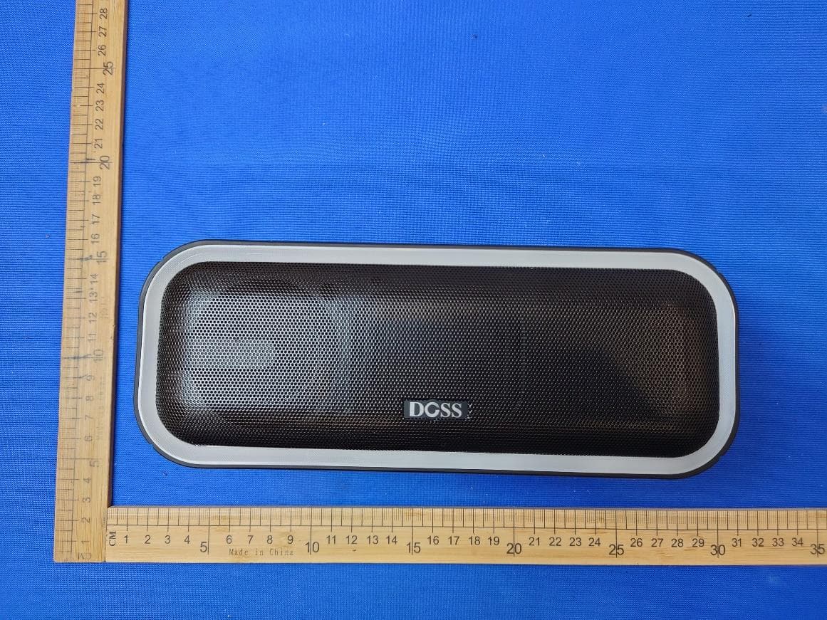
WC2-WB20
May 09, 2024Wireless Bluetooth Speaker
Equipment Class
DSS - Part 15 Spread Spectrum Transmitter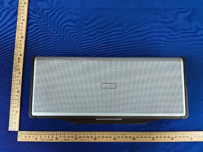
WC2-WB565
Dec 21, 2023Home Speaker
Equipment Class
DSS - Part 15 Spread Spectrum Transmitter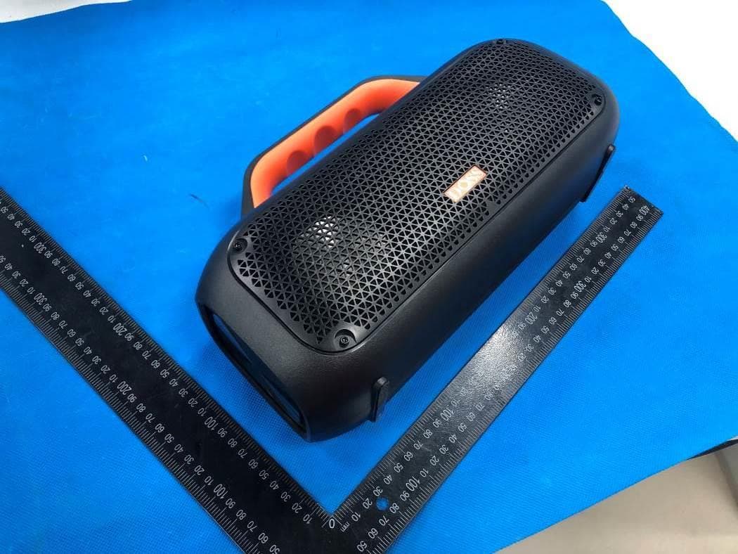
WC2-WB507
Jun 08, 2022Portable Waterproof Speaker
Equipment Class
DSS - Part 15 Spread Spectrum Transmitter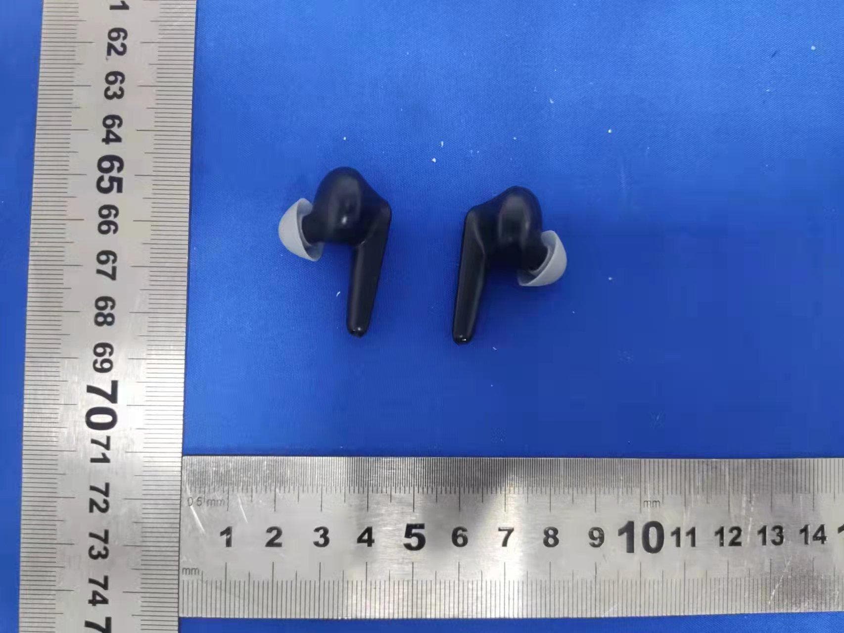
WC2-P1
Apr 07, 2022True Wireless Earbuds
Equipment Class
DXX - Part 15 Low Power Communication Device Transmitter
WC2-WB206
May 10, 2020Wireless Bluetooth Speaker
Equipment Class
DSS - Part 15 Spread Spectrum Transmitter