WFK-RCBT001Headshower Remote
Grohe AG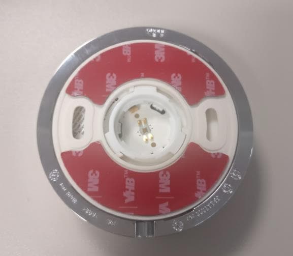
Click to zoom
Application Details
- Equipment Class
- JAB - Part 15 Class B Digital Device
- Date of Grant
- Feb 19, 2020
- Application Purpose
- Original Equipment
- Date of Application
- Feb 19, 2020
- Equipment Note
- Headshower Remote
- Company
- Grohe AG
- Country
- Germany
Documents & Files
Document Text
Text extracted from the exhibit documents filed with the FCC. Open a document above to read the original.
Users Manual
DESIGN + ENGINEERING GROHE GERMANY www.grohe.com RAINSHOWER 310 SMARTCONNECT 99.1365.031/ÄM 245110/01.20 6 26 640 26 642 26 641 26 644 26 643 26 645 26 646 1522 - 33 - 4 7 - 89 - 4849 - 5051 I 1 26 643 26 645 26 642 * 26 64026 641 26 644 26 646 2 1. 45° 2. 1 2a 1. 2. 24h 2b GROHE Deutschland Vertriebs GmbH Zur Porta 9 D-32457 Porta Westfalica 3 max.10m max 32,8 ft I 4 1. 2. 3x 3. min. 30 sec. 4. 5. 6. min. 30 sec. * 24mm 3. 2. 1. 2,5mm 45° 45 3. 1. 2. max. 5 min. 4. 5. 3 6 I 5 I 6 >3 sec. >3 sec. 2 sec. 2 sec. >30 min. >30 min. >30 min. 1. 2. 1. 2. 1. 2. I 7 3x CR 2032 2. 45° 1. 3 2,5mm 1. 2. 45° 21 I 8 3x 3x AAA 2. 1. 24mm 9 D Anwendungsbereich Kopfbrause mit Fernbedienung zur drahtlosen Umstellung der Strahlarten. Allgemeine Informationen Die Installation und die Nutzung unterliegen den geltenden nationalen Bestimmungen. Für Schäden, die durch Nichtbeachtung der Betriebsanleitungen entstehen, wird keine Haftung übernommen. Betriebsbedingungen Störquellen Die Sender-/Empfängereinheit arbeitet im ISM-Frequenz- band (2,4 GHz). Die Installation in der Nähe von Geräten mit gleicher Kanalbelegung (z.B. WLAN-Geräte, HF Kom- ponenten, etc. [Herstellerdokumentation beachten!]) ist zu vermeiden. Hindernisse/Barrieren Bei Betrieb unter ungünstigen Umgebungsbedingungen, in Gebäuden/Räumen mit Stahlbetonwänden, Stahl und Eisen- rahmen oder in der Nähe von Hindernissen (z.B. Möbelstücke) aus Metall, kann der Funkempfang gestört und unterbrochen werden. Batteriehinweise Zur Erstinbetriebnahme die mitgelieferten Batterien verwenden. Beim Einlegen der Batterien auf richtige Polung achten! Nur Batterien des gleichen Typs verwenden. Immer alle Batterien gleichzeitig austauschen, keine gebrauchten und neue Batterien miteinander mischen. Gebrauchte Batterien nicht aufladen bzw. nicht versuchen durch Wärme oder andere Mittel zu reaktivieren. Wiederaufladbare Batterien dürfen nicht verwendet werden. Erschöpfte Batterien müssen umgehend aus dem Gerät genommen werden, erhöhte Auslaufgefahr! Technische Daten • Fließdruck:min. 0,1 MPa / empfohlen 0,15–0,5 MPa • Betriebsdruck:max. 0,5 MPa • Prüfdruck:1,6 MPa • Temperatur - Warmwassereingangmax. 70 °C - Zur Energieeinsparung empfohlen60 °C • relative Luftfeuchtigkeit: max. 80 %rH • Umgebungstemperatur: 15 - 45 °C • Funkfrequenz:2,402 ... 2,483 GHz • Sendeleistung:< 10 mW • Batterie Fernbedienung: 1x 3 V-Lithium Batterie (Typ CR 2032) • Batterien Kopfbrause: 3x AAA Batterie • Schutzart Fernbedienung: IP 57 Elektrische Prüfdaten • Software-Klasse:A • Verschmutzungsgrad:2 Installation, siehe Seite 3 und 4. Pairing Pairing bedeutet die erstmalige Kopplung zwischen zwei Geräten. Nach Einlegen der Batterien ist der Pairing Modus bis zu 5 Minuten aktiv, die rote LED an der Fernbedienung blinkt. Bei erfolgtem Pairing hört die LED auf zu blinken. Montage der Kopfbrause Bei Montage z.B. an Gipskartonwänden (keine feste Wand) muss sichergestellt sein, dass eine ausreichende Festigkeit durch eine entsprechende Verstärkung in der Wand vorhan- den ist. Montage des Brausearmes Siehe zusätzlich beiliegende Installationsanweisung. Funktionsprüfung, siehe Seite 4 Abb. [6]. Um zu testen, ob das Pairing erfolgreich war, muss direkt nach der Installation eine Funktionsprüfung durchgeführt werden. Dazu Wasserzufuhr über die installierte Armatur freigeben. Werkseitig ist der GROHE PureRain-Strahl (gleichmäßiger Strahl mit großen und weichen Tropfen) voreingestellt. Durch Drücken der Tasten auf der Fernbedienung kann die Strahlart verändert werden: GROHE ActiveRain (kraftvoller Strahl aus der Mitte der Brause) oder beide Strahlarten sind parallel aktiviert Sollte das Umstellen nicht funktionieren, müssen die folgenden Schritte in weniger als 5 Minuten durchgeführt werden: • Batterie aus Fernbedienung entnehmen, 30 Sekunden warten und neu einsetzen oder ersetzen • Batterien aus Kopfbrause entnehmen, 30 Sekunden warten und neu einsetzen oder ersetzen Bedienung, siehe Seite 5. Die Strahlart kann nur bei Wasserfluss eingestellt werden. Nach dem Schließen der Wasserzufuhr bleibt die zuletzt verwendete Strahlart für 30 Minuten als Start-Strahlart ausgewählt. Danach startet die Brause bei erneuter Wasserzufuhr wieder in der voreingestellten Strahlart. Strahlartvoreinstellung , siehe Seite 6. Durch Drücken einer Taste länger als 3 Sekunden wird die entsprechende Strahlart als Start-Strahlart voreingestellt. Bei Start des Wasserflusses nach mehr als 30 Minuten Unterbrechung startet die Brause in dieser Strahlart. Wartung Batteriewechsel, siehe Seite 7 und 8. Die Indikatoren, die das notwendige Batteriewechseln signalisieren, starten bei einer Restkapazität der Batterie von ca. 10% (siehe Störung/Ursache/Abhilfe). Das Pairing zwischen Kopfbrause und Fernbedienung bleibt bestehen. Hinweis: Die vom Benutzer gespeicherte Einstellung bleibt auch nach einem Batteriewechsel oder bei entladener Batterie erhalten. Art der Barriere Stör- bzw. Abschirmungs- potenzial Holz, KunststoffNiedrig Wasser, Ziegel, MarmorMittel Putz, Beton, Glas, Massivholz Hoch MetallSehr hoch 10 Brause, siehe Seite 8. 5 Jahre Garantie auf die gleich bleibende Funktion der SpeedClean-Düsen. Entsorgungshinweis Geräte mit dieser Kennzeichnung gehören nicht in den Hausmüll, sondern müssen gemäß der landesspezifischen Vorschriften getrennt entsorgt werden. Störung / Ursache / Abhilfe GB Applications Head shower with remote control for wireless diversion of spray patterns. General information Installation and use are subject to applicable national provisions. No liability can be accepted for damage occurring due to non-observance of the operating instructions. Operating conditions Interference sources The transmitter/receiver unit operates in the ISM frequency band (2.4 GHz). Installation in proximity to devices with the same frequency band (e.g. Wi-Fi devices, HF components, etc. [observe manufacturer documentation!]) should be avoided. Obstructions/barriers Wireless reception can be impaired and interrupted under unfavourable surround…
Text truncated - open the document above for the full version.
External Photos
Rainshower 310 SmartConnect (26646) FCC ID: WFK‐RCBT001 IC ID: 7787A‐RCBT001
ID Label/Location Info
Rainshower 310 SmartConnect (26646) FCC ID: WFK‐RCBT001 IC ID: 7787A‐RCBT001
Internal Photos
Rainshower 310 SmartConnect (26646) FCC ID: WFK‐RCBT001 IC ID: 7787A‐RCBT001
Internal Photos
Rainshower 310 SmartConnect (26646) FCC ID: WFK‐RCBT001 IC ID: 7787A‐RCBT001 In PCB integrated Antenna
Test Report
Page 1 of 6 The test results relate only to the individual items which have been tested. This report shall not be reproduced in parts without the written approval of the testing laboratory © Copyright: All rights reserved by CETECOM Annex 1: Measurement diagrams to T E S T R E P O R T No.: 19-1-0142201T09a According to: FCC Regulations Title 47, Part 15 Subpart B (Unintentional radiators) §15.109 ISED-Regulations ICES-003, Issue 6 for GROHE AG Rainshower 310 SmartConnect (26646) Remote Control FCC ID: WFK-RCBT001 IC ID: 7787A-RCBT001 Laboratory Accreditation and Listings Accredited EMC-Test Laboratory accredited according to DIN EN ISO/IEC 17025:2018 CETECOM GmbH Laboratory Radio Communications & Electromagnetic Compatibility Im Teelbruch 116 • 45219 Essen • Germany Registered in Essen, Germany, Reg. No.: HRB Essen 8984 Tel.: + 49 (0) 20 54 / 95 19-0 • Fax: + 49 (0) 20 54 / 95 19-150 E-mail: [email protected] • Internet: www.cetecom.com Annex 1 to Test Report 19-1-0142201T09a, Page 2 of 6 CETECOM_TR19_1_0142201T09a_A1 Table of contents 1. MEASUREMENT DIAGRAMS OF EMISSION TEST 3 Annex 1 to Test Report 19-1-0142201T09a, Page 3 of 6 CETECOM_TR19_1_0142201T09a_A1 1. Measurement diagrams of emission test 1.1. Diagrams of radiated field strength emissions, 30 MHz - 1 GHz (Diagram group 03) 3.01a Common Information Test Description: Electric Fieldstrength Measurement Test Spec.: EN 55022B: 3m meas. distance in the anechoic room Antenna: receiving antenna is directed to all sides, h=1.55m height Operating Mode: BT Environmental Conditions:: Humidity : 40% rH; Temperature: 20° C Operator: LKu Verdict: Passed EUT Information PMT number: 19-1-01422S31 Manufacturer: Grohe AG Product: Rainshower 310 SmartConnect (26646) Model: Remote Control HW version: GH_RC-1V3 SW version: n/a Serial number: 0Z051-4119-00137-21 Power Supply: 3 V Battery 0 10 20 30 40 50 60 30M5060 80 100M200300400 500 8001G L e v e l i n d B μ V / m Frequency in Hz Full Spectrum FCC15.209 Final_Result Frequency (MHz) QuasiPeak (dBμV/m) Limit (dBμV/m) Margi n (dB) Meas. Time (ms) Bandwidth (kHz) Height (cm) PolAzimuth (deg) Corr. (dB/m) 927.174000 33.88 46.00 12.12 1000.0 120.000 257.0 H 207.0 27.0 (continuation of the "Final_Result" table from column 16 ...) Frequency (MHz) Comment 927.174000 15:20:00 - 31.01.2020 Annex 1 to Test Report 19-1-0142201T09a, Page 4 of 6 CETECOM_TR19_1_0142201T09a_A1 3.01_standing Common Information Test Description: Electric Fieldstrength Measurement Test Spec.: EN 55022B: 3m meas. distance in the anechoic room Antenna: receiving antenna is directed to all sides, h=1.55 m height Operating Mode: BT Environmental Conditions:: Humidity : 40% rH; Temperature: 20° C Operator: LKu Verdict: PassedComment: Comment: standing EUT Information PMT number: 19-1-01422S31 Manufacturer: Grohe AG Product: Rainshower 310 SmartConnect (26646) Model: Remote Control HW version: GH_RC-1V3 SW version: n/a Serial number: 0Z051-4119-00137-21 Power Supply: 3 V Battery 0 10 20 30 40 50 60 30M5060 80 100M200300400 500 8001G L e v e l i n d B μ V / m Frequency in Hz Full Spectrum FCC15.209 Final_Result Frequency (MHz) QuasiPeak (dBμV/m) Limit (dBμV/m) Margin (dB) Meas. Time (ms) Bandwidth (kHz) Height (cm) PolAzimuth (deg) Corr. (dB/m) 792.824000 27.47 46.00 18.53 1000.0 120.000 253.0 H 143.0 25.1 928.332000 35.76 46.00 10.24 1000.0 120.000 368.0 H 172.0 27.0 (continuation of the "Final_Result" table from column 16 ...) Frequency (MHz) Comment 792.824000 15:46:44 - 31.01.2020 928.332000 15:41:40 - 31.01.2020 Annex 1 to Test Report 19-1-0142201T09a, Page 5 of 6 CETECOM_TR19_1_0142201T09a_A1 1.2. Diagrams of radiated emission above 1 GHz (Diagram group 04) 4.01a Common Information Test Description: Radiated field strength emission in 3m distance Test Site: CETECOM GmbH Essen Test Standard: FCC 15.109 Unintentional Radiator Antenna polarization: horizontal/vertical Operating Mode: 15B Operator: TFra Environmental Conditions: Humidity : 40% rH; Temperature: 20° C EUT Setup: Verdict: Failed EUT Information PMT number: 19-1-01422S31 Manufacturer: Grohe AG Product: Rainshower 310 SmartConnect (26646) Model: Remote Control HW version: GH_RC-1V3 SW version: n/a 25 30 35 40 45 50 55 60 65 70 75 80 85 1G2G3G4G5G6 8 10G18G L e v e l i n d B μ V / m Frequency in Hz Full Spectrum FCC15_109_PK FCC15_109_AV Final_Result Frequency (MHz) MaxPeak (dBμV/m) RMS (dBμV/m) Limit (dBμV/m) Margin (dB) Meas. Time (ms) Bandwidth (kHz) Height (cm) PolAzimuth (deg) Elevati on (deg) Corr. (dB/m) 3499.426333 42.54 --- 74.00 31.46 100.0 1000.000 155.0 V 327.0 90.0 4 16243.91366 7 --- 61.53 54.00 -7.53 100.0 1000.000 155.0 H 225.0 90.0 28 17111.77533 3 63.70 --- 74.00 10.30 100.0 1000.000 155.0 V 285.0 0.0 30 17186.06066 6 --- 64.30 54.00 -10.30 100.0 1000.000 155.0 H 18.0 0.0 30 17648.67333 3 --- 63.06 54.00 -9.06 100.0 1000.000 155.0 H -13.0 0.0 29 Annex 1 to Test Report 19-1-0142201T09a, Page 6 of 6 CETECOM_TR19_1_0142201T09a_A1 Diagram No. 4.01b END OF ANNEX
Test Report
Page 1 of 17 The test results relate only to the individual items which have been tested. This report shall not be reproduced in parts without the written approval of the testing laboratory © Copyright: All rights reserved by CETECOM T E S T R E P O R T No.: 19-1-0142201T09a According to: FCC Regulations Title 47, Part 15 Subpart B (Unintentional radiators) §15.109 ISED-Regulations ICES-003, Issue 6 for GROHE AG Rainshower 310 SmartConnect (26646) Remote Control FCC ID: WFK-RCBT001 IC ID: 7787A-RCBT001 Laboratory Accreditation and Listings Accredited EMC-Test Laboratory accredited according to DIN EN ISO/IEC 17025:2018 CETECOM GmbH Laboratory Radio Communications & Electromagnetic Compatibility Im Teelbruch 116 • 45219 Essen • Germany Registered in Essen, Germany, Reg. No.: HRB Essen 8984 Tel.: + 49 (0) 20 54 / 95 19-0 • Fax: + 49 (0) 20 54 / 95 19-150 E-mail: [email protected] • Internet: www.cetecom.com Test Report 19-1-0142201T09a, Page 2 of 17 CETECOM_TR19_1_0142201T09a Table of contents 1. SUMMARY OF TEST RESULTS 3 1.1. TEST OVERVIEW ACCORDING FCC PART 15B AND CANADIAN RSS- OR ICES STANDARDS 3 1.2. ATTESTATION 3 2. ADMINISTRATIVE DATA 4 2.1. Identification of the testing laboratory 4 2.2. Test location 4 2.3. Organizational items 4 2.4. Applicant’s details 4 2.5. Manufacturer’s details 4 3. EQUIPMENT UNDER TEST (EUT) 5 3.1. EUT: Type, S/N etc. and short descriptions used in this test report 5 3.2. Auxiliary Equipment (AE): Type, S/N etc. and short descriptions 5 3.3. EUT set-ups 5 3.4. EUT operating modes 5 3.5. Additional declaration and description of EUT 6 3.6. Configuration of cables used for testing 6 4. DESCRIPTION OF TEST SYSTEM SET-UP’S 7 4.1. Test system set-up for radiated electric field measurement 30 MHz to 1 GHz 7 4.2. Test system set-up for radiated electric field measurement above 1 GHz 8 5. MEASUREMENTS 9 5.1. General Limit - Radiated field strength emissions, 30 MHz - 1 GHz 9 5.2. General Limit – Radiated field strength emissions, above 1 GHz 10 5.3. Measurement uncertainties 11 6. ABBREVIATIONS USED IN THIS REPORT 12 7. ACCREDITATION DETAILS OF CETECOM’S LABORATORIES AND TEST SITES 12 8. INSTRUMENTS AND ANCILLARY 13 8.1. Used equipment 13 9. VERSIONS OF TEST REPORTS (CHANGE HISTORY) 17 Table of annexTotal pages Annex 1: Measurement diagrams (separate document) CETECOM_TR19_1_00142201T09a_A1 6 Annex 2: External photographs of EUT (separate document) CETECOM_TR19_1_00142201T09a_A2 3 Annex 3: Test setup photographs (separate document) CETECOM_TR19_1_00142201T09a_A3 4 The listed attachments are an integral part of this report. Test Report 19-1-0142201T09a, Page 3 of 17 CETECOM_TR19_1_0142201T09a 1. Summary of test results The test results apply exclusively to the test samples as presented in this Report. The CETECOM GmbH does not assume responsibility for any conclusions and generalizations taken in conjunction with other specimens or samples of the type of the item presented to tests. Also we refer on special conditions which the applicant should fulfill according §2.927 to §2.948, special focus regarding modification of the equipment and availability of sample equipment for market surveillance tests. The Equipment Under Test (in this report, hereinafter referred as EUT) is a digital device with no support of radiofrequency technologies. A typical operating mode (one or more) as used in the real usage was tested or a special test program simulating this was used. Pls. see chapter Operating-Mode for more details. Following tests have been performed to show compliance with applicable FCC Part 15, Subpart B (Unintentional Radiators) of the CFR 47 Rules, Edition 1 st October 2018 and Canadian ICES-003, Issue 6. 1.1. TEST OVERVIEW ACCORDING FCC PART 15B AND CANADIAN RSS- OR ICES STANDARDS No. of Diagram group Test Cases Port References, Standards & Limits EUT set-up EUT op- mode Result FCC ISED Limits 3 Radiated emissions 30 MHz - 1 GHz Cabinet + Inter- connecting cables §15.109 ICES-003, Issue 6 (ANSI C63.4) Class A Class B 1 1 passed 4 Radiated emissions above 1 GHz Cabinet + Inter- connecting cables §15.109 ICES-003, Issue 6 (ANSI C63.4) Class A Class B 1 1 passed Remark: 1.2. ATTESTATION I declare that all measurements were performed by me or under my supervision and that all measurements have been performed and are correct to my best knowledge and belief to Innovation, Science and Economic Development Canada standards. All requirements as shown in above table are met in accordance with enumerated standards. ...................................................... .................................................... Markus Ridder H. Laayouni Responsible for test section Responsible for test report Test Report 19-1-0142201T09a, Page 4 of 17 CETECOM_TR19_1_0142201T09a 2. Administrative Data 2.1. Identification of the testing laboratory Company name: CETECOM GmbH Address: Im Teelbruch 116 45219 Essen - Kettwig Germany Responsible for testing laboratory: Volker Wittmann Deputy: Ninovic Perez 2.2. Test location 2.2.1. Test laboratory “CETECOM GmbH” Company name: see chapter 2.1. Identification of the testing laboratory 2.3. Organizational items Responsible for test report and project leader: H. Laayouni Receipt of EUT: 2020-01-21 Date(s) of test: 2020-01-22 to 2020-02-05 Date of report: 2020-02-12 ----------------------------------------------------------------------------------------------------------------------------------------------------- Version of template: 13.03 2.4. Applicant’s details Applicant’s name: GROHE AG Address: Industriepark Edelburg 58675 Hemer Germany Contact person: Ralf Oberste-Lehn 2.5. Manufacturer’s details Manufacturer’s name: please see applicant's details Address: please see applicant's details Test Report 19-1-0142201T09a, Page 5 of 17 CETECOM_TR19_1_0142201T09a 3. Equipment under test (EUT) 3.1. EUT: Type, S/N etc. and short descriptions used in this test report Short descrip- tion*) EUT Type S/N serial number HW hardware status SW so…
Text truncated - open the document above for the full version.
Test Setup Photos
Page 1 of 4 The test results relate only to the individual items which have been tested. This report shall not be reproduced in parts without the written approval of the testing laboratory © Copyright: All rights reserved by CETECOM Annex 3: Test Setup Photographs to T E S T R E P O R T No.: 19-1-0142201T09a According to: FCC Regulations Title 47, Part 15 Subpart B (Unintentional radiators) §15.109 ISED-Regulations ICES-003, Issue 6 for GROHE AG Rainshower 310 SmartConnect (26646) Remote Control FCC ID: WFK-RCBT001 IC ID: 7787A-RCBT001 Laboratory Accreditation and Listings Accredited EMC-Test Laboratory accredited according to DIN EN ISO/IEC 17025:2018 CETECOM GmbH Laboratory Radio Communications & Electromagnetic Compatibility Im Teelbruch 116 • 45219 Essen • Germany Registered in Essen, Germany, Reg. No.: HRB Essen 8984 Tel.: + 49 (0) 20 54 / 95 19-0 • Fax: + 49 (0) 20 54 / 95 19-150 E-mail: [email protected] • Internet: www.cetecom.com Annex 3 to Test Report 19-1-0142201T09a, Page 2 of 4 CETECOM_TR19_1_0142201T09a_A3 Table of contents 1. TEST SET UP PHOTOGRAPHS 3 Annex 3 to Test Report 19-1-0142201T09a, Page 3 of 4 CETECOM_TR19_1_0142201T09a_A3 1. Test set up photographs Photograph 1: Radiated measurements test set-up Photograph 2: Radiated measurements test set-up Annex 3 to Test Report 19-1-0142201T09a, Page 4 of 4 CETECOM_TR19_1_0142201T09a_A3 Photograph 3: Radiated measurements test set-up, 1 GHz – 26 GHz Photograph 4: Radiated measurements test set-up, 1 GHz – 26 GHz END OF ANNEX
Contact Information
Applicant
Joerg Buechner(Approval Manager)
Test Firm
cetecom advanced GmbHGerald Schmidt
Technical Specifications
| # | Rule Parts | Frequency Range | Power Output |
|---|---|---|---|
| 1 | 15B | - | - |
Other Applications from Grohe AG
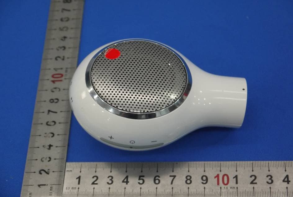
WFK26270
Nov 23, 2015Wireless shower speaker
Equipment Class
DSS - Part 15 Spread Spectrum Transmitter
WFK-SPABT01
Feb 18, 2015F-digital deluxe Bluetooth-unit
Equipment Class
DSS - Part 15 Spread Spectrum Transmitter