WHQ20000310PAM 3000 Bed Sensor Panel
Wireless 2000 RF & UWB Technologies Ltd.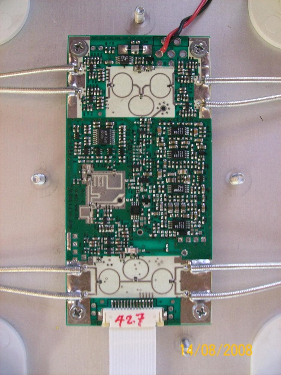
Click to zoom
Application Details
- Equipment Class
- UWB - Ultra Wideband Transmitter
- Date of Grant
- Dec 28, 2008
- Application Purpose
- Original Equipment
- Date of Application
- Aug 24, 2008
- Equipment Note
- PAM 3000 Bed Sensor Panel
- Frequency Range
- 3400.00000000 - 5000.00000000
- Country
- Canada
Documents & Files
Document Text
Text extracted from the exhibit documents filed with the FCC. Open a document above to read the original.
Users Manual
Patient Assessment Monitor PAM™3000 Installation and Maintenance Guide Document p/n 100.100.19.04 Page 1 of 7 Rev 04 DOCUMENT TITLE Installation and Maintenance Guide DOCUMENT #: 100.100.19.04 DOCUMENT REVISION #: 04 REVISION HISTORY Revision Date Reason For Change Author 00 09.Mar.2006 Preliminary Draft E. Gavrilovich 01 07.Apr.2008 Rev history and FCC standards added, Environmental conditions changed as in CSA report Eli A 02 22.Apr.2008 P/N added to “System Hardware Installation”, troubleshooting table added Eli A 03 29.May.2008 Grammatical and spelling errors fixed Eli A 03 14.Jul.2008 BSI&CSA logo removed, FCC notice included Eli A Proprietary Information This document contains proprietary information which is protected by copyright. All rights reserved. Reproduction, adaptation, or translation without prior written permission is prohibited, except as allowed under the copyright laws . Wireless 2000 RF & UWB Technologies Ltd. 2421 Alpha Avenue Burnaby, BC, V5C 5L2 Canada Patient Assessment Monitor PAM™3000 Installation and Maintenance Guide Document p/n 100.100.19.04 Page 2 of 7 Rev 04 1 Introduction This Guide provides safety information, maintenance guidelines and cleaning instructions for the PAM™3000 Patient Assessment Monitor system. 2 System Description PAM™3000 is for use in the US and Canada. The PAM™3000 system consists of Bed Sensor (200.003.10.00), RBS Repeater Base Station (200.001.10.00), CBS Central Base Station (200.002.10.00) and software. 3 System Hardware Installation 3.1 Installing the Bed Sensor Regulatory Notice This equipment may only be operated indoor. Operations outdoor is in violation of 47 U.S.C. 301 and could subject the operator to serious legal penalties FCC information Product Name: PAM 3000 Bed Sensor Panel Model number: WHQ20000310 3.1.1 Step 1: Power Supply Find the power supply in the shipping box and unpack it. Only the approved Power Supply (Wireless2000 p/n 375.001.10.00) and Power Cord (Wireless2000 p/n 506.001.10.00) shipped with PAM™3000 should be used. Attach the power supply to the closest to the headboard tubular crossbar of the bed frame with the Velcro ties as shown. Route DC output cable as shown and fasten it with the Velcro ties to the bed frame. The DC plug should be placed near the top Patient Assessment Monitor PAM™3000 Installation and Maintenance Guide Document p/n 100.100.19.04 Page 3 of 7 Rev 04 section of the bed surface, as shown. Route AC power cord as shown and fasten it with the Velcro ties to the bed frame. Plug the AC power cord into the approved AC wall outlet. 3.1.2 Step 2: Bed Sensor Unpack the bed sensor. Record its serial number and the room number for the location identification during the admission procedure. Pull up or slide down the bed mattress to expose the top section of the bed. Place bed sensor on the bed 18” (46 cm) away from the headboard and ensure that bed sensor’s plastic cover is facing up and the bed sensor’s DC power jack is oriented toward the footboard. Insert DC plug of the power supply into the DC jack of the bed sensor and tighten the outer ring of the plug to prevent its accidental unplugging. 3.1.3 Step 3: Calibration To perform successful self-calibration procedure, ensure that the bed is vacant and there is no motion within 1 meter from the bed for 10 minutes. The bed sensor is now calibrated and ready for integration into the PAM system. 3.2 Installing the Repeater Base Station (RBS): The locations to install the RBSs and the necessary number of RBS units were determined during the Initial Facility Assessment (IFA). Please consult the IFA Report. Install the RBS up on the wall near the ceiling by using mounting screws supplied. Attach the DC plug of the DC power adapter (supplied) to the RBS DC jack and insert the AC plug into the nearest AC wall receptacle. Alternately, the RBS may be mounted above the suspended ceiling. Patient Assessment Monitor PAM™3000 Installation and Maintenance Guide Document p/n 100.100.19.04 Page 4 of 7 Rev 04 3.3 Installing the Central Base Station (CBS): The system requires only one CBS unit per facility’s floor. Install the CBS by plugging its cable into the USB port of designated PC and placing the unit on the desk next to PC. For proper operation ensure that the label on the CBS enclosure is facing up. Improper orientation of the CBS may greatly decrease system’s communication range. 4 Replacement Parts List 200.003.10.00 – Bed Sensor 200.001.10.00 – Repeater Base Station 200.002.10.00 – Central Base Station 5 Technical Information Model: PAM™3000 Type of protection against electric shock: Class 1 Degree of protection against electric shock: Type BF, Applied part 6 Environmental Specifications: 6.1 Operating Ambient temperature range: 10°C to 40°C (50°F to 104°F) Relative humidity: 30% to 75%, non-condensing Altitude: Sea level to 3000m max (10,000 Ft) 6.2 Transport and Storage Ambient temperature range: -10°C to +60°C (+14°F to 140°F) Relative humidity: 5% to 95%, non-condensing Altitude: Sea level to 12,000m (40,000 Ft) Patient Assessment Monitor PAM™3000 Installation and Maintenance Guide Document p/n 100.100.19.04 Page 5 of 7 Rev 04 6.3 Applicable Requirements: UL 60601-1 (1 st Edition) Medical Electrical Equipment, Part 1: General Requirements for Safety IEC 601-1:1988 + A1:1991 + A2:1995 Safety of Medical Electrical Equipment, Part 1: General Requirements for Safety IEC/EN 60601-1-2 Medical Electrical Equipment, Part 1: General Requirements for Basic Safety and Essential Performance. Collateral standard, EMC Safety With respect to ELECTRICAL SHOCK, FIRE, MECHANICAL and OTHER specified hazards in accordance with CAN/CSA C22.2 No.601.1- M90 Safety of Medical Electrical Equipment, Part 1: General Requirements for Safety CAN/CSA C22.2 No.601.1S1-94 Supplement No. 1-94 to CAN/CSA C22.2 601.1-M90 CAN/CSA C22.2 No.601.1B-98 Amendment 2 to CAN/CSA C22.2 601.1-M90 EN 61000-4, IEC 61000-4 in accordance with FCC part 15/B, 15/C, 15/F Power Supply complies with UL…
Text truncated - open the document above for the full version.
Cover Letter(s)
2421 Alpha Avenue, Burnaby, BC, V5C 5L2 Ph. (604) 298-8471 Fax (604) 298-8470 CONFIDENTIALITY REQUEST 7th October 2008 Federal Communications Commission Authorization and Evaluation Division 7435 Oakland Mills Road Columbia, MD 21046 USA Subject: Wireless 2000 RF & UWB Technologies Ltd. FCC ID: WHQ20000310 To Whom It May Concern: We request for confidentiality for exhibits Part List and Schematics (UWB) pursuant to 47 CFR 0.459 of the Commission Rules. Should you have any questions or require any further information with regards to this, please feel free to contact me. Sincerely, Eli Abramzon Engineer
Cover Letter(s)
2421 Alpha Avenue, Burnaby, BC, V5C 5L2 Ph. (604) 298-8471 Fax (604) 298-8470 CONFIDENTIALITY REQUEST 8nd December 2008 Federal Communications Commission Authorization and Evaluation Division 7435 Oakland Mills Road Columbia, MD 21046 USA Subject: Wireless 2000 RF & UWB Technologies Ltd. FCC ID: WHQ20000310 To Whom It May Concern: Pursuant to 47 CFR 0.459 of the Commission Rules we request for confidentiality for exhibits below: BSP_Part List.PDF Part List BSP_Schem1.PDF Schematics (UWB) BSP_Block_Diagram.PDF Block Diagram Pursuant to DA04-1705 June 15, 2004 of the Commission’s public notice, we also request temporary confidential treatment for BSP_IntPho.PDF Internal Photos We ask for temporary confidentiality for the time period before mass production begins. We believe that the exhibits above contain confidential information that might be used to reverse engineer our product prior to mass production. Should you have any questions or require any further information with regards to this, please feel free to contact me. Sincerely, Eli Abramzon Engineer
External Photos
Aug 14, 2008 Page 1 of 2 BSP External Photos Aug 14, 2008 Page 2 of 2 1 BSP with cover
ID Label/Location Info
Patient Assessment Monitor PAM™3000 Label Position Page 1 of 2 1 Introduction This document is a reference for label placement on the PAM 3000 Bed Sensor Panel. The Label appearance and its placement must be consistent for engineering and production units. 2 Label appearance The compliancy PAM 3000 label (Wireless 2000 P/N 621.001.10.00) is a matt silver aluminium foil adhesive type, made from 3M-7940 material. It must contain the follow information: a) Wireless 2000 logo b) Model name c) CSA regulatory notice of using unique accessories ( Power supply W2K P/N 375.001.10.00) d) CSA regulatory notice of proper grounding e) Manufacturer name f) CSA Master Contract number g) Type BF applied part logo as per IEC 60417-5333 h) FCC ID number Fig. 1 PAM 3000 Label Patient Assessment Monitor PAM™3000 Label Position Page 2 of 2 3 Label Placement The label should be placed on the lower part of the PAM 3000 Bed Sensor Panel (power connector facing down) from the left side of a power jack. The lower edge of the label should be not closer than 2cm from the lower edge of the Bed Sensor. The left edge of the label should be as fare as 7 cm from the center line of the Bed Sensor, referring to the power jack. Fig.2 Label Placement Wireless 2000 RF & UWB Technologies Ltd. 2421 Alpha Avenue Burnaby, BC, V5C 5L2 Canada
Internal Photos
2421 Alpha Avenue, Burnaby, BC, V5C 5L2 Ph. (604) 298-8471 Fax (604) 298-8470 Aug 14, 2008 Page 1 of 7 BSP Internal Photos 2421 Alpha Avenue, Burnaby, BC, V5C 5L2 Ph. (604) 298-8471 Fax (604) 298-8470 Aug 14, 2008 Page 2 of 7 Table of Contents 1 BSP Radar Board........................................................................................................................................................................... 3 1.1 The Radar board without shield .......................................................................................................................................... 3 1.2 The Radar Board with a shield ........................................................................................................................................... 4 2 The Antenna Board ....................................................................................................................................................................... 5 3 The Communication Board ........................................................................................................................................................... 6 4 Full internal Assembly .................................................................................................................................................................. 7 Revisions Date Rev Prepared Approved Comment Aug 14, 2008 0.0 Eli A. First draft Acronyms BSP – Bed Sensor Panel Aug 14, 2008 Page 3 of 7 1 BSP Radar Board 1.1 The Radar board without shield Aug 14, 2008 Page 4 of 7 1.2 The Radar Board with a shield Aug 14, 2008 Page 5 of 7 2 The Antenna Board Aug 14, 2008 Page 6 of 7 3 The Communication Board Aug 14, 2008 Page 7 of 7 4 Full internal Assembly
Operational Description
PAM™3000 Bed Sensor Panel Operational Description Page 1 of 2 DOCUMENT TITLE Bed Sensor Panel Operational Description DOCUMENT #: 200.003.23.01 DOCUMENT REVISION #: 01 REVISION HISTORY Revision Date Reason For Change Author 00 May 16, 2008 Preliminary V. Goldenberg 01 August 13, 2008 Released V. Goldenberg Proprietary Information This document contains information which is exclusive property of Wireless 2000 RF & UWB Technologies Ltd. Reproduction or use by others is not permitted without the express written consent of Wireless 2000 RF & UWB Technologies Ltd. Wireless 2000 RF & UWB Technologies Ltd. 2421 Alpha Avenue Burnaby, BC, V5C 5L2 Canada PAM™3000 Bed Sensor Panel Operational Description Page 2 of 2 Operational Description PAM™3000 bed sensor is a wireless device intended for monitoring heart and respiration rates of patients in healthcare and medical environments. The sensor is a ultra- wideband (UWB) radar which is capable of detecting movements of heart and lungs inside the human body. The bed sensor is placed underneath the bed mattress and transmits UWB pulses towards the patient lying on top of the mattress. Applications of this system are mainly in healthcare and elder care industries. PAM™3000 bed sensor is a composite device consisting of an ultra-wideband radar, a conventional radio transceiver operating in a 902-928MHz range and associated digital and analog circuitry. The bed sensor panel contains an array of 4 UWB radiating elements and 48 UWB receive elements which are permanently attached and integral to the device. The signal conditioning and processing is done on-board with the results sent through the 902- 928MHz radio link to a monitoring station through a repeater. The bed sensor contains pressure elements for patient detection and shuts the UWB radar off when the patient is not on the bed. Sensor Diagram
Test Report
EMC Compatibitity Medicat Report Rev 't.O Wireless 2000 - PAM rM3000 Bed Sensor Panel Wireless 2000 PAM TM3OOO Bed Sensor Panel (BsP) CE Mark EMC Directive Compliance Test Report lEC6060 1-1-2:3'd Ed. :2OOi"'General Requirements for Basic Safety and Essential Performances Standard for Emissions & lmmunity Report lc lcEs-003 Approval Checked by Johanson, Technical Manager 2r,/0deS Date Protocol Data Systems Inc, EMC Testing Lab, Abbotsford BG, Canada SCC tSO/17025 (CAN-P-4E) Accredited Laboratory No. 612 FCC O.A.T.S. Registration Number 96437 Industry Canada O.A.T.S. Registration Number 1C3384 This report is for the exclusive use of Protocol Data Systems Customerand is provided pursuant to the agreement between protocol and its Customer. Protocol's responsibility and liability are limited to the terms and conditions of the agreement Protocol assumes no liability to any party, other than to the Customer in accordance with the agreement, for any loss, expense or damage occasioned by the use of this report. Only the Customer is authorized to copy or distribute this report and then only in its entirety. Any use of the Protocol Data Systems name for the sale or advertisement of the tested material, product or service must first be approved in writing by Protocol Data Systems. The observations and test results in this report are rglgyqq!of !y !q lhe ganplelg leslqd and of Measurements to & FCC CFR47 Part 15/B for Emissions Revision 1.0 August 0'1, 2008 Reoort Number: 03265 Page 1 of 27 EMC Compatibility Medical Report Rev 1.0 Wireless 2000 – PAM ™3000 Bed Sensor Panel Report Number: 03265 Page 2 of 27 Index Section I: Report of Measurements Testing Information .................................................................... 3 Section II: Report of Measurements for CE Mark Emissions .............................................................. 5 Part 1 - Conducted Emission Testing ................................................................................. 6 Part 2 - Radiated Emission Testing .................................................................................... 7 Section III: Report of Measurements per IC ICES-003......................................................................... 8 Part 1 - Conducted Emission Testing ................................................................................. 9 Part 2 - Radiated Emission Testing .................................................................................. 10 Section IV: Report of Measurements per FCC CFR47 Part 15/B ....................................................... 11 Part 1 - Conducted Emission Testing ............................................................................... 12 Part 2 - Radiated Emission Testing .................................................................................. 13 Section V: Report of Measurements to Immunity Testing.................................................................. 14 Part 1 - ESD Testing ........................................................................................................ 16 Part 2 - Radiated Immunity Testing (A.M.) ....................................................................... 18 Part 3 - EFT/Burst Testing (Fast Transient - AC Power Supply and I/O Lines) ............... 19 Part 4 - Surge Transient Immunity .................................................................................... 21 Part 5 - Conducted Immunity Testing (A.M.) .................................................................... 22 Part 6 - Dips and Interruptions Testing ............................................................................. 23 Appendix A: Report of Measurements EUT Photos.............................................................................. 24 Appendix B: Report of Measurement Data and Plots ........................................................................... 25 Conducted Emission Plots ................................................................................................ 26 EMC Compatibility Medical Report Rev 1.0 Wireless 2000 – PAM ™3000 Bed Sensor Panel Report Number: 03265 Page 3 of 27 Section I: Report of Measurements Testing Information Testing Details TESTED BY: Emissions Testing: David Johanson/ Dan Petrulian Immunity Testing: David Johanson TEST CONDITIONS: Temperature and Humidity: July 1, 2008 26.0°C, 60% TEST VOLTAGE: 120Vac, 60Hz, 230Vac, 50Hz Testing Lab Protocol Data Systems Inc. EMC Testing Lab 28945 McTavish Rd. Abbotsford BC, Canada, V4X 2E7 SCC ISO/17025 (CAN-P-4E) Accredited Laboratory No. 612 FCC O.A.T.S. Registration Number 96437 Industry Canada O.A.T.S. Registration Number IC3384 Test Equipment List EMISSION: Manufacturer Model Equipment Description Serial No. Next Cal HP 85650A CDN Quasi-Peak Adapter 2043A00240 18/09/09 HP 85662A Spectrum Analyzer Display 2318A05184 18/09/09 HP 8566B Spectrum Analyzer RF Section 2241A02102 18/09/09 HP 85685A RF-Preselector 3107A01222 18/09/09 LaPlace Instruments AC1000 Low Distortion Power Source 138041 01/11/08 Thurlby Thandar HA1600 Power and Harmonics Analyzer 140108 01/11/08 Solar 8012-50-R-24 LISN 863092 28/09/08 EMCO CPA-30 Ant Log Periodic 200-1000MHZ 563 05/12/08 EMCO 3110B Ant Biconical 20-300MHz 9401-1850 05/12/08 Fischer F-33-1 VHF-UHF Current Clamp 725 01/04/09 AH Systems SAS-200/550-1 Active Monopole Antenna 631 08/05/09 EMCO 6502 Active Loop Antenna 9002-2489 28/02/09 Rhientech Custom Antenna Mast N/A N/A Protocol EMC Custom Turntable N/A N/A IMMUNITY: Manufacturer Model Equipment Description Serial No. Next Cal EIN 3100L RF Amplifier 309 N/A Amplifier Research 30W1000M7 RF Amplifier 22606 N/A HD Communications HD18876 RF Amplifier 1003 N/A HP 8657A Signal Generator 2913A00373 N/A HP 8672A Signal Generator (2-18GHz) 1930A00890 N/A HP 11721A Frequency Doubler (100-2600MHz) 1950A02276 N/A Schaffner NSG432 ESD Simulator: 1243 01/12/09 Keytek EMC-Pro CE Combination Tester * 0312235 22/01/09 Fischer CustomCommu. F-140 Bulk In…
Text truncated - open the document above for the full version.
Test Report
EMC Compliance Test Report Rev 2.0 Wireless 2000 – PAM TM 3000 15.249 Report Number: 03265-1 Page 2 of 15 Index Section I: Report of Measurements Testing Information .................................................................... 3 Section II: Report of Measurements Test Procedure.......................................................................... 5 Section III: Report of Measurements to Radiation Interference............................................................ 6 Section IV: Report of Maximum Permissible Exposure......................................................................... 7 Section V: Report of Measurements to Occupied Bandwidth............................................................ 11 Section VI: Report of Measurements to Power Line Conducted Interference .................................... 13 Section VII: Report of Measurements EUT Photos.............................................................................. 15 EMC Compliance Test Report Rev 2.0 Wireless 2000 – PAM TM 3000 15.249 Report Number: 03265-1 Page 3 of 15 Section I: Report of Measurements Testing Information General Information Applicant Company Name Wireless 2000 RF & UWB Technologies Ltd. Address 2421 Alpha Avenue Burnaby, BC V5C 5L2 Phone: 604-298-8471 Fax 604-298-8470 Contact Person: Vlad Goldenberg Email: [email protected] Product Name PAM ™3000 Bed Sensor Panel FCC ID# WHQ20000310 Applicable Standard FCC Part 15.517, ANSI C63.4:2003 ; Part 15.207, 15.209 Test Results Pass Related Report/s Approval 1) Wireless 2000 UWB 15.517 03265-2 Rev 1.0.PDF for Pt 15.517 Indoor UWB device 2) Wireless 2000 FCC IC 03265 Rev 1.0.pdf for Pt 15.209 digital interface portion. Statement of Compliance This equipment has been tested in accordance with the standards indentified in the referenced test report. To the best of our knowledge and belief, these tests were performed using the measurement procedures described in this report and demonstrate that the equipment complies with the appropriate standards. – Signature on Front Cover Page. Equipment Under Test Specification Manufacturer Wireless 2000 RF & UWB Technologies Ltd. Product Description Bed Sensor Panel FCC ID WHQ20000310 Model Number 20000310 Name PAM ™3000 Bed Sensor Panel Operating Frequency 902-928MHz Emission Designator DSS EUT Power Source 5Vdc from Jerome Power Supply Test Item Production Unit Type of Equipment Mobile Antennas Internal PCB Antenna Connector permanently attached Test Voltage 120Vac 60Hz Test Environment Test Facility Protocol Data Systems Inc. 28945 McTavish Road Abbotsford, BC V4X 2E7 Phone: 604-607-0012 Fax: 604-607-0019 Email: [email protected] Website: www.protocol-emc.com Test Facility ID’s SCC ISO/17025 (CAN-P-4E) Accredited Laboratory No. 612 FCC O.A.T.S. Registration Number 96437 Industry Canada O.A.T.S. Registration Number IC3384 Date Tested 2April08 Tested By David Johanson EMC Compliance Test Report Rev 2.0 Wireless 2000 – PAM TM 3000 15.249 Report Number: 03265-1 Page 4 of 15 Test Setup Test Supporting Equipment 120Vac to 5Vdc Power Supply Manufacturer: Jerome Industries Part Number: WSC150M Test Conditions Temperature and Humidity: 7.0°C, 87% Test Exercise e.g. software description, test signal, etc. The EUT was set for continuous transmit mode of operation. It was tested using a wireless connection from a remotely located Laptop running the Radiotronix program Wi232DTSTest.exe and the Wireless 2000 program GUI_VitalViewer Deviation from Standard/s No deviation from Standard Modification to the EUT No modifications was made. Test Equipment List EMISSION Manufacturer Model Equipment Description Serial No. Next Cal HP 85650A CDN Quasi-Peak Adapter 2043A00240 18/09/09 HP 85662A Spectrum Analyzer Display 2318A05184 18/09/09 HP 8566B Spectrum Analyzer RF Section 2241A02102 18/09/09 HP 85685A RF-Preselector 3107A01222 18/09/09 Solar 8012-50-R-24 LISN 863092 28/09/08 EMCO CPA-30 Ant Log Periodic 200-1000MHZ 563 05/12/08 EMCO 3110B Ant Biconical 20-300MHz 9401-1850 05/12/08 EMCO 3115 DGR Horn At. 1-18GHzMHz 3429 15/12/08 AH Systems SAS-200/550-1 Active Monopole Antenna 631 08/05/09 EMCO 6502 Active Loop Antenna 9002-2489 28/02/09 Rhientech Custom Antenna Mast N/A N/A Protocol EMC Custom Turntable N/A N/A Measurement Uncertainty Parameter Uncertainty Radio Frequency ±1 x 10⁻⁵ Total RF power, conducted ±1,5 dB RF power density, conducted ±3 dB Spurious emissions, conducted ±3 dB All emissions, radiated ±3 dB Temperature ±1°C Humidity ±5 % DC and low frequency voltages ±3 % EMC Compliance Test Report Rev 2.0 Wireless 2000 – PAM TM 3000 15.249 Report Number: 03265-1 Page 5 of 15 Section II: Report of Measurements Test Procedure Radiation Interference: The measurement was made per ANSI C63.4-2003 using an Agilent model 8566B spectrum analyzer, a model 85685A Preselector, a model 85650A quasi-peak adapter, and the appropriate antenna. The analyzer was calibrated in dB above a microvolt at the output of the antenna. The resolution bandwidth was 100kHz with an appropriate sweep speed and the video bandwidth was 300kHz up to 1GHz and 1MHz with a VBW greater than or equal to the RBW above 1GHz. When an emission was found, the table was rotated to produce the maximum, signal strength. The antenna was placed in both the horizontal and vertical planes and the worse case emissions were reported. The EUT was re-positioned to produce the highest emission level. The spectrum was searched to at least the tenth (10) harmonic of the fundamental. Formula of Conversion Factors: The field strength at 3m was established by adding the meter reading of the spectrum analyzer (which is set to read in units of dBμV) to the antenna correction factor supplied by the antenna manufacturer. The antenna correction factors are stated in terms of dB. The gain of the Preselector was accounted for in the spectrum analyzer meter reading. Example: Freq (MHz) Meter Reading +ACF +CL = FS 330 20 dBμV +10.36 dB +0.5 = 30.86 dBμV/m @ 3m Where…
Text truncated - open the document above for the full version.
Test Report
EMC Compliance Test Report Rev 2.0 Wireless 2000 – PAM TM 3000 15.517 Report Number: 03265-2 Page 2 of 13 Index Section I: Report of Measurements Testing Information .................................................................... 3 Section II: Report of Measurements Test Procedure.......................................................................... 5 Section III: Report of Measurements to Radiation Interference............................................................ 6 Section IV: Report of Measurements to Occupied Bandwidth .............................................................. 8 Section V: Report of Maximum Permissible Exposure....................................................................... 10 Section VI: Report of Measurements to Power Line Conducted Interference .................................... 11 Section VII: Report of Measurements EUT Photos.............................................................................. 13 EMC Compliance Test Report Rev 2.0 Wireless 2000 – PAM TM 3000 15.517 Report Number: 03265-2 Page 3 of 13 Section I: Report of Measurements Testing Information General Information Applicant Company Name Wireless 2000 RF & UWB Technologies Ltd. Address 2421 Alpha Avenue Burnaby, BC V5C 5L2 Phone: 604-298-8471 Fax 604-298-8470 Contact Person: Vlad Goldenberg Email: [email protected] Product Name PAM ™3000 Bed Sensor Panel FCC ID# WHQ20000310 Applicable Standard FCC Part 15.517, ANSI C63.4:2003 ; Part 15.207, 15.209 Test Results Pass Related Report/s Approval 1) Wireless 2000 15.249 03265-1 Rev 1.0.PDF for Pt 15.249 Low Power device 2) Wireless 2000 FCC IC 03265 Rev 1.0.pdf for Pt 15.209 digital interface portion. Statement of Compliance This equipment has been tested in accordance with the standards indentified in the referenced test report. To the best of our knowledge and belief, these tests were performed using the measurement procedures described in this report and demonstrate that the equipment complies with the appropriate standards. – Signature on Front Cover Page. Equipment Under Test Specification Manufacturer Wireless 2000 RF & UWB Technologies Ltd. Product Description Bed Sensor Panel FCC ID WHQ20000310 Model Number 20000310 Name PAM ™3000 Bed Sensor Panel Operating Frequency 3.5-4.5GHz Emission Designator UWB EUT Power Source 5Vdc from Jerome Power Supply Test Item Production Unit Type of Equipment Mobile Antennas Internal PCB Antenna Connector permanently attached Test Voltage 120Vac 60Hz Test Environment Test Facility Protocol Data Systems Inc. 28945 McTavish Road Abbotsford, BC V4X 2E7 Phone: 604-607-0012 Fax: 604-607-0019 Email: [email protected] Website: www.protocol-emc.com Test Facility ID’s SCC ISO/17025 (CAN-P-4E) Accredited Laboratory No. 612 FCC O.A.T.S. Registration Number 96437 Industry Canada O.A.T.S. Registration Number IC3384 Date Tested 2July08 Tested By David Johanson EMC Compliance Test Report Rev 2.0 Wireless 2000 – PAM TM 3000 15.517 Report Number: 03265-2 Page 4 of 13 Test Setup Test Supporting Equipment 120Vac to 5Vdc Power Supply Manufacturer: Jerome Industries Part Number: WSC150M Test Conditions Temperature and Humidity: 7.0°C, 87% Test Exercise e.g. software description, test signal, etc. The EUT was set for continuous transmit mode of operation. Deviation from Standard/s No deviation from Standard Modification to the EUT No modifications was made. Test Equipment List EMISSION Manufacturer Model Equipment Description Serial No. Next Cal HP 85650A CDN Quasi-Peak Adapter 2043A00240 18/09/09 HP 85662A Spectrum Analyzer Display 2318A05184 18/09/09 HP 8566B Spectrum Analyzer RF Section 2241A02102 18/09/09 HP 85685A RF-Preselector 3107A01222 18/09/09 Solar 8012-50-R-24 LISN 863092 28/09/08 EMCO CPA-30 Ant Log Periodic 200-1000MHZ 563 05/12/08 EMCO 3110B Ant Biconical 20-300MHz 9401-1850 05/12/08 EMCO 3115 DGR Horn At. 1-18GHzMHz 3429 15/12/08 AH Systems SAS-200/550-1 Active Monopole Antenna 631 08/05/09 EMCO 6502 Active Loop Antenna 9002-2489 28/02/09 Rhientech Custom Antenna Mast N/A N/A Protocol EMC Custom Turntable N/A N/A Measurement Uncertainty Parameter Uncertainty Radio Frequency ±1 x 10⁻⁵ Total RF power, conducted ±1,5 dB RF power density, conducted ±3 dB Spurious emissions, conducted ±3 dB All emissions, radiated ±3 dB Temperature ±1°C Humidity ±5 % DC and low frequency voltages ±3 % EMC Compliance Test Report Rev 2.0 Wireless 2000 – PAM TM 3000 15.517 Report Number: 03265-2 Page 5 of 13 Section II: Report of Measurements Test Procedure Radiation Interference: The measurement was made per ANSI C63.4-2003 using an Agilent model 8566B spectrum analyzer, a model 85685A Preselector, a model 85650A quasi-peak adapter, and an appropriate antenna. The analyzer was calibrated in dB above a microvolt at the output of the antenna. The resolution bandwidth was 100kHz with an appropriate sweep speed and the video bandwidth was 300kHz up to 1GHz and 1MHz with a VBW greater than or equal to the RBW above 1GHz. When an emission was found, the table was rotated to produce the maximum, signal strength. The EUT was tested in various orientations and rotated to maximize the signal strength. The antenna was placed in both the horizontal and vertical planes for each EUT orientation and the worse case emissions were reported…
Text truncated - open the document above for the full version.
Contact Information
Applicant
Eli Abramzon(RF Engineer)
Technical Contact
Wireless 2000 RF & UWB Technologies Ltd.Vlad Goldenberg
[email protected]604-298-8471
2421 Alpha Avenue · Burnaby · Canada
Test Firm
Protocol LabsRobert Stirling
Technical Specifications
| # | Rule Parts | Frequency Range | Power Output |
|---|---|---|---|
| 1 | 15F | 3.40 GHz - 5.00 GHz | - |