WIZSYNCROEX6Radio control transmitter
Kyosho Corporation of America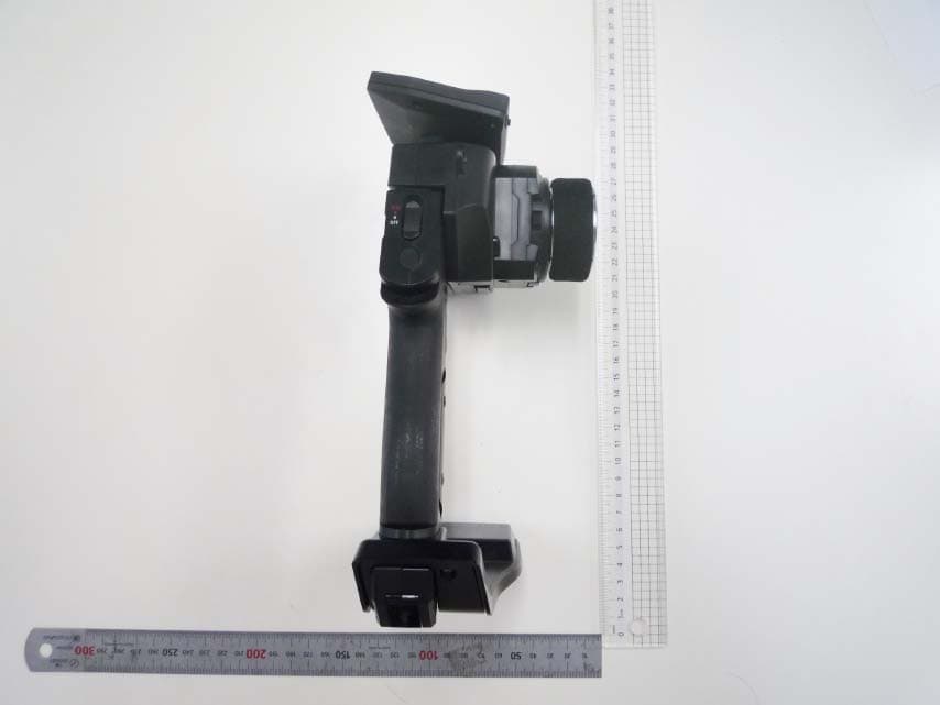
Click to zoom
Application Details
- Equipment Class
- DTS - Digital Transmission System
- Date of Grant
- Jun 23, 2015
- Application Purpose
- Original Equipment
- Date of Application
- Jun 21, 2015
- Equipment Note
- Radio control transmitter
- Frequency Range
- 2404.00000000 - 2480.00000000
- Country
- United States
Documents & Files
Document Text
Text extracted from the exhibit documents filed with the FCC. Open a document above to read the original.
Users Manual
THE FINEST RADIO CONTROL MODELS R *Specifications are subject to be changed without prior notice! DIGITAL PROPORTIONAL SYSTEMDIGITAL PROPORTIONAL SYSTEM Before beginning assembly, please read these instructions thoroughly. © Copyright 2015 KYOSHO CORPORATION / 82030-T01 Instruction Manual 2 Title Title PagePage ■ Table of Contents ■ Table of Contents 2 ■ For Safe Operation 3 ■ Getting Started 5 ●Transmitter Assembly 5 ●Transmitter Dismantling 5 ■ Names of Parts 6 ●ET Keys (1-3) and BT Button (1) 7 ●Steering Adjustment 7 ●Wheel Cap Removal 7 ●Throttle Adjustment 7 ●Throttle Position Adjustment 7 ●Colored Grip and Pad Replacement 7 ●Unit Connector 8 ●Power Switch 8 ■ Preparations 9 ●Battery Installation 9 ●Battery Level Warning 9 ● Initializing EX-6 10 ●How to change the Modulation 10 ●Pairing 11 ■ Procedures Prior to Operation 12 ●Trim and Sub Trim Operation 13 ■ Operating procedure 14 ●STEERING 14 ●THROTTLE 15 ●3CH 4CH operation 16 ■ Display and Control Method with the Xpansion unit attached 17 ●Basic Operations to Change Settings 17 ●How to attach Xpansion unit 18 ●Startup Screen and Initial Screen 19 ●VR information setting 20 ●How to change the Modulation mode 20 ●Pairing 21 ■TOP MENU 22 ■□□ FUNCTION 24 ● Model Menu (Model) 24 ▶Model Select (MDL-Select) 24 ▶Model Name (MDL-Name) 24 ▶Model Copy (MDL-Copy) 25 ▶Model Reset (MDL-Reset) 25 ● TIMER MENU 26 ▶TRGSTART (Trigger Start) 26 ▶LAP HISTORY (Lap History) 26 ▶ALARM (Alarm) 26 ●KEYSET (Key setting MENU) 27 ●3・4CH (3・4Channel) 28 ▶2WAY(2WAY) 28 ▶3WAY(3WAY) 28 ▶5WAY(5WAY) 29 ▶ANALOG (Analog mixing MENU) 29 ▶GYRO (GYRO mixing MENU) 29 ▶TWIN SERVO (Twin servo mixing MENU) 30 ▶4WS (4WS mixing MENU) 30 ▶AMP (AMP mixing MENU) 31 ▶T-MIX (Throttle mixing MENU) 32 ●TRIM SET (Trim SET MENU) 33 ▶STEER AUTO TRIM (Steering auto trim) 33 ▶STEER AUTO BALANCE (Steering auto balance Left) 33 ▶STEER AUTO BALANCE (Steering auto balance Right) 3 3 ●SYSTEM MENU 34 ▶DISPLAY MENU 34 ▶BATTERY TYPE 34 !WARNING! Warning Display 35 ▶CALCULATOR 36 ▶SOUND MENU 36 ▶VR INFORMATION Volume information 36 ▶KEYSPEED 37 ▶OPERATIN ALARM 37 □■□STEERING MENU 38 ●TRAVEL MENU 38 ▶ST TRAVEL Steering Travel 38 ▶ST BALANCE L R Seering Balance L R 38 ●TRIM MENU 39 ▶ST TRIM Steering Trim 39 ▶ST SUBTRIM Steering Subtrim 39 ▶ST TRIMRATE Steering Trimrate 39 ●ST SPEED Steering Speed 40 ▶ST TURN Steering Turn Speed 40 ▶ST RETURN Steering Return Speed 40 ●DYNAMC Steering Dynamics 41 ▶CURVE Steering curve 41 ▶PUNCH Steering punch 41 ●FEEL MENU 42 ▶ST FEEL Steering feel MENU 42 ●REVERSE Steering Reverse 42 ▶ST REVERSE Steering Reverse 42 □□■THROTTLE MENU 43 ●TRAVEL Throttle travel 43 ▶TH TRAVEL F Throttle Travel F 43 ▶TH TRAVEL B Throttle Travel B 43 ●TRIM MENU 44 ▶TH TRIM Throttle Trim 44 ▶TH SUBTRIM Throttle Subtrim 44 ▶TH TRIMRATE Throttle Trimrate 44 ●TH SPEED Throttle Speed 45 ▶TH TURN Throttle Turn Speed 45 ▶TH RETURN Throttle Return Speed 45 ●DYNAMC Throttle Dynamics 46 ▶CURVE Throttle Curve 46 ▶PUNCH Throttle punch 46 ●FEEL Throttle feel MENU 47 ▶TH FEEL Throttle feel 47 ●OVERRIDE Throttle Override 48 ●REVERSE Throttle Reverse 48 ▶TH REVERSE Throttle Reverse 48 ●CYCLE Throttle Cycle 49 ▶ACCEL Throttle Acceleration 49 ▶ABS Throttle ABS 49 ●ATSTART Throttle Auto-Start 50 ●OFFSET Throttle OFFSET 51 ■ Glossary 52 ■ FCC statement 55 ■ Specifications 55 3 ■ For Safe Operation 4 5 ■ Getting Started Insert the Grip Unit into the Master Unit, then attach the Steering Unit. Detach the Steering Unit, then detach the Master Unit. ● Transmitter Assembly● Transmitter Dismantling 1. 1. 2. 2. 3. 3. Remove the connector cover before use. If storing the transmitter in dismantled form, please remember to attach the connector covers. (separately available option: Kondo Kagaku Co., Ltd.) Assembly may differ with the included set contents. [Legend] P :Point:Notice Steering Unit Release Button Steering Unit Release Button Steering Unit Lock Lever Steering Unit Lock Lever Grip Unit Lock Lever Grip Unit Release Button Grip Unit Master Unit Master Unit Steering Unit Steering Unit ※ Assembled ※ Depending on the model, expansion unit has been installed at the factory. 6 Antenna EXP Connector Cover Power Switch (P.8) LED Steering Unit Release Button (P.5) Colored Grip (P.7) Colored Pad (P.7) ● ET Keys (1-3) and BT Button (1) Functions may be assigned to the keys/button. Steering Unit Lock Lever (P.5) Throttle Trigger (P.7) Grip Unit Lock Lever (P.5) Grip Unit Release Button (P.5) Throttle Trigger Position Adjuster (P.7) ET1 (P.7) BT1 (P.7) ET2 (P.7) ET3 (P.7) ■ Names of Parts 《Front View》《Side View》 《Rear View》 The possible functions which each key/ button may be assigned to are different. The tabs on the colored grip and pad are to be inserted into holes. Note the direction. Make sure the battery box or battery pack is removed before replacing the colored grip and pad. Note direction of the of the colored grip and pad 7 ● Steering Wheel Adjustment ● Throttle Trigger Adjustment ● Wheel Cap Remove ● Throttle Trigger Position Adjustment ●Colored Grip and Pad Replacement ● ET Keys (1-3) and BT Button (1) Functions may be assigned to the keys/button. The possible functions which each key/button may be assigned to are different. Colored grip pad (optional: Kondo Kagaku Co., Ltd.) and Large/small grip pad options are available. Remove the two screws on each side of the grip to detach the grip plates, then attach the colored grip and pad. 《How to change》 Adjust the tension of the steering wheel spring. Insert a 1.5mm hex wrench referring to the image below. Rotate clockwise to increase tension and counterclockwise to decrease it. [How to Adjust] Hex Wrench Excessive counterclockwise rotation will result in the wheel being unable to return to neutral position. In this case, rotate clockwise until the wheel returns to neutral. Temperature and aging, because it may become loose by the strong impact or the like, it is recommended that you adhere to such cases. In the case where there is a thing that would loose still, p…
Text truncated - open the document above for the full version.
Users Manual
19 ● Startup Screen and Initial Screen When the transmitter is switched on, the startup screen will display, followed by the initial screen. ※ Pressing the ENTER key during the startup screen will allow you to proceed to the initial screen. ① ① ⑤ ⑦ ⑥ ⑧ ② ③ ④ ① Function Monitor: Functions that are active will be lit up. ② Steering Trim Monitor: Displays the position of the steering trim. ③ Throttle Trim Monitor: Displays the position of the throttle trim. ④ Top menu: Display three kinds of setting items FUNCTION Modify settings related to functions. STEERING Modify settings related to the steering. THROTTLE Modify settings related to the throttle. ⑤Power Source Type: Displays the type of battery being used. ⑥ Voltage: Displays the current power source voltage. ⑦ Model Number: Displays the currently selected model number. ⑧ Model Name: Displays the name of the currently selected model number. ① Version Information : Displays the version of the program that is installed in the Master Unit's CPU. This product's performance may be upgraded via paid or free upgrades. Check the Kyosho website for information regarding such upgrades. ( http://www.kyosho.com ) 【 Startup Screen 】 【 Initial Screen 】 LP:Li-po LF:Li-Fe DR:R03/AAA/UM4 Alkaline Batteries NI:Ni-MH OR : Steering and Brake travel Override AUT : Throttle Auto Start CYC : Cycle (Throttle Acceleration/Throttle ABS) OFS : Offset (Drag Brake/Idle Up) (Notice) If you switch battery types, make sure to also change the [Battery Management] setting. 20 ● VR information setting Adjust the steering and throttle resistance information. ※ Please perform the VR information configuration to calibrate your system. ○ When using EX-6 for the first time. ○ When changing a steering unit for a different product or when putting it back together. ○When changing a grip unit for a different product or when putting it back together. ○ When using and confusion has occurred in the positional information. 1.Select [FUNCTION] on the initial screen and push the ENTER key. 2.Select [SYSTEM] on the function screen and push the ENTER key. 3.Select [VR INFO] on the system screen and push the ENTER key. 4.Move the wheel slowly to the full left and right lock (numbers will change as the steering is moved) and release the wheel back to neutral. 5.Move the trigger slowly to the full throttle and full brake positions (numbers will change as the throttle is moved) and release the trigger back to neutral. 6.Then select YES (press ENTER) to adjust and save the settings. 4,5, Move slowly to full stroke, then release. 3.Example before setting 6, Small window [Yes] comes active. ※ When operating the VR INFORMATION and pressing the BACK key will cancel the operation. ●How to change the Modulation mode EX-6 has two Modulation modes. ※ When attaching the Xpansion unit, this operation is the same. ① Turn off EX-6 switch. ② Push the ET1 lever to the left and power on. ③ Hold ET1 lever until the buzzer sounds and the LED of EX-6 turns on (approximately two seconds). ● MINI-Z ASF mode: LED Solid ASF support of MINI-Z series is steerable. ● MINI-Z MHS mode :LED Flashing slowly Oparating MINI-Z MHS mode. (MR-03 VE PRO) Only MINI-Z with ASF/MHS system are operable. FHS (MINI-Z sports) it will not be able to steer the. If the pilot LED is blinking fast, this is a warning that the battery voltage is low. Please change to new batteries or for a battery pack which has been charged. Model selection changes and modulation mode changes are not linked. Power ON ↓ ↓ ↓ ET1 Approximately two seconds, LED turns on. 《Functions》 21 ① Bring distance of EX-6 and MINI-Z close to about 10cm. ② Switch on MINI-Z while pushing the pairing button of MINI-Z. Pushing pairing button Switch on LED ③ After the MINI-Z's LED has lit up, release the pairing button. Then check that the MINI-Z's LED lights up again (indicating pairing completion) ① Switch off MINI-Z. ② Switch off the EX-6 main power, then switch on EX-6 again. ③ Bring distance of EX-6 and MINI-Z close to about 30cm. Switch on the MINI-Z and check that the receiver LED is lit. If the LED flashes, the MINI-Z is not getting the EX-6 signal and the pairing procedure should be repeated. Preparing the MINI-Z 2. Preparations for Operation 3. If the mode is changed(General or France), please conduct pairing procedures with the MINI-Z you are using again. 10cm ● Pairing Preparing the Transmitter ① While pushing the ET2 lever up, power on. The pilot LED lights up, release ET2 lever. Case of using the Xpansion unit ※ Refer to p.11 pairing Operation when not using the Xpansion unit. In order for the receiver to operate, it must store the transmitter's unique ID in its memory in a process called “pairing.” Even if a single transmitter is used to control multiple receivers, each receiver must go through the pairing process with the transmitter before being used for the first time. ※ Please adjust the modulation mode before pairing. (p.20) A receiver does not work normally in a different mode. 1. ET2 Power ON ↓ ↓ ↓ <France mode pairing > FRANCE mode pairing is possible when the ET2 lever is released after LED turns off. Please use this feature if the situation is needed. ② Displays the initial screen, then pairing display is shown. (indicating transmitter is transmitting the pairing signal.) Or have someone else the pairing in the vicinity, when the pairing work does not work under the influence of wireless LAN, microwave ovens, please perform again shifted or time for a little bit and away from there. 22 Model Menu (MODEL) Operations such as selecting or copying a model. Steering Travel Modify the overall amount of steering movement. 3CH/4CH Menu (3/4ch) Modify settings related to 3CH and 4CH. Steering Dynamics Modify the movement speed ratio which corresponds to steering angle and Modify how much the steering initially turns from neutral position. Trim set Menu (TRIM SET) Easy adjust function for steering trim and balance. Steering Feel Modify the feeling of the steering…
Text truncated - open the document above for the full version.
Users Manual
41 DYNAMC Steering Dynamics Settings related to steering control. ▶ CURVE Steering Curve Modify the movement speed ratio which corresponds to steering angle. ▶ PUNCH Steering Punch Modify how much the steering initially turns from neutral position. ▶CURVE Steering Curve ▶ PUNCH Steering Punch This function adjusts the ratio of the steering angle to servo movement speed (Curve Characteristics). Choose between (+) Quick Curve and (-) Mild Curve. This function quickens the steering's initial response and can be used to instill a strong turning movement when the steering initially moves from neutral. 【Setting Range】 ST CURVE : -100〜 0 〜 100% (Default : 0%) 【Setting Range】 ST PUNCH : 0〜 50% (Default : 0%) 【Example】 Modify the movement speed ratio which corresponds to steering angle. As the graph shows, servo movement speed can be changed according to wheel movement angle.Positive values (+1 to +100) equal high initial response followed by mild response. Negative values (-1 to -100) equal a mild initial response followed by high response. P The larger the value, the stronger the amount of turning movement. P When using this in conjunction with other functions such as [Steering Speed], adjust one at a time to confirm their effects to produce an effective overall setting. P To adjust only the steering's initial response, use the [Steering Punch] function. P This could be effective if steering linkages have a lot of slop, but please note that it does not improve straight- line performance. P When using this in conjunction with other functions such as [Steering Speed], adjust one at a time to confirm their effects to produce an effective overall setting. P 42 FEEL Steering feel MENUREVERSE Steering Reverse FEEL function provides changing the moving peformance of steering servo. ▶ ST FEEL Steering Feeling Adjust steering feeling. ▶ TH FEEL F Throttle feel F Refer to "Throttle Feel F" (p.47) ▶ TH FEEL B Throttle feel B Refer to "Throttle Feel B" (p.47) ▶ST FEEL Steering Feel ▶ST REVERSE Steering reverse FEEL function provides changing the cornering peformance feeling. Modify the steering direction. 【Setting Range】 ST FEEL : -50〜 0 〜 50% (Default: 0%) 【Setting Range】 ST REVERSE :NORM(Normal), REVS(Reverse) (Default : NORM) TH REVERSE : Refer to "Throttle Reverse" (p.48) Take into account such factors as the car, driving surface, etc. when adjusting Steering feel settings. Conduct test drives to find the best setting values. P 43 THROTTLE TRAVEL Throttle Travel Settings related to throttle control. ▶ TH TRAVEL F Throttle Travel F Modify the maximum amount of throttle movement (towards forward acceleration). ▶ TH TRAVEL B Throttle Travel B Modify the maximum amount of throttle brake movement. Adjust the maximum amount of throttle forward acceleration movement. ▶TH TRAVEL F Throttle Travel F The key setting displays [T:HIPOINT]. P Throttle will not operate if the High Point value is set to 0. Brake will not operate if the BRAKE value is set to 0. Adjust the maximum amount of brake movement. 【Setting Range】 TH TRAVEL F : 0〜 150 (Defaul : 100) 【Setting Range】 TH TRAVEL B : 0〜 150 (Default : 100) ▶TH TRAVEL B Throttle Travel B The key setting displays [T:BRAKE]. P 44 TRIM Throttle Trim Settings related to throttle control. ▶ TH TRIM Throttle Trim Modify the neutral position of the throttle. ▶ TH SUBTRIM Throttle Subtrim Shift the overall throttle movement range. ▶ TH TRIMRATE Throttle Trimrate Modify the amount of movement which corresponds to one click of the throttle trim button. Adjusts the neutral/center position of the throttle range. ▶TH TRIM Throttle Trim Setting adjustments prior to driving should be carried out with the sub trim, not the trim. P The setting range cannot exceed what is set by [Throttle Travel F] or [Throttle Travel B]. P Adjust the position of the overall throttle movement range. ※ Also refer to Trim and Sub Trim Operation. (p.13) Adjusts the amount of movement associated with one click of the throttle trim button. 【Setting Range】 TH TRIM : F50〜 0 〜 B50 (Default : 0) 【Setting Range】 TH SUBTRIM : F80〜 0 〜 B80 (Default : 0) 【Setting Range】 TH TRIM RATE : 1〜 10 (Default : 5) ▶TH SUBTRIM Throttle Subtrim TH TRIMRATE Throttle Trimrate The amount of movement of one interval can be adjusted, the lower the number the smaller the amount of movement. The overall number of intervals does not change, so a change in trim rate will result in a change in the range in which the trim can be used to make corrections. If the trim rate is changed when the trim is already set, the trim may be thrown off. If the trim setting is 0 then this does not apply.) P P P 45 TH SPEED Throttle Speed Settings related to throttle control. ▶ TH TURN Throttle Turn Speed Modify the speed of the throttle's movement (towards forward acceleration). ▶ TH RETURN Throttle Return Speed Modify the speed of the throttle's return movement. This function delays the conversion of the throttle control signal to make the car easier to control. This function delays the conversion of the throttle control signal to make the car easier to control. ※ The [TURN] direction is adjusted with [Throttle Turn Speed]. 【Setting Range】 TH TURN SPEED : 1〜 100% (Default : 100%) 【Setting Range】 TH RETURN SPEED : 1〜 100% (Default : 100%) ▶TH TURN Throttle Turn Speed TH RETURN Throttle Return Speed For each setting, it has changed the optimal numerical value in a variety of factors, such as your car, the road surface. Conduct test drives to find the best setting values. P For each setting, it has changed the optimal numerical value in a variety of factors, such as your car, the road surface. Conduct test drives to find the best setting values. P 【Example】 If the car spins or otherwise does not drive straight when the throttle is applied suddenly, limiting the throttle speed can be effective. 【Example】 If the car spins or otherwise does not drive straight when the throttle is lowered suddenly, limiting the throttle speed can be effective. 46 DYNAMC Thro…
Text truncated - open the document above for the full version.
Cover Letter(s)
020415 08 KONDO KAGAKU CO.,LTD. 4-17-7 Higashi-Nippori, Arakawa-ku Tokyo, Japan 116-0014 Authority to Act as Agent Date: 26 May, 2015 American Certification Body, Inc. 6731 Whittier Avenue Suite C110 McLean, VA 22101 To Whom It May Concern: SGS RF Technologies Inc. is authorized to act on our behalf, until otherwise notified, for applications to American Certification Body, Inc. (ACB). We certify that we are not subject to denial of federal benefits, that includes FCC benefits, pursuant to Section 5301 of the Anti-Drug Abuse Act of 1988, 21 U.S.C. 862. Further, no party, as defined in 47 CFR 1.2002 (b), to the application is subject to denial of federal benefits, that includes FCC benefits. Thank you, Agency Agreement Expiration Date: 26 May, 2016 By: __________________________ Katsuhisa Nakazono (Signature 1 ) (Print name) Title: Manager On behalf of: KONDO KAGAKU CO., LTD. (Company Name) Telephone: +81-(0)3-3807-7751 1 - Must be signed by applicant contact given for applicant on the FCC site, or by the authorized agent if an appropriate authorized agent letter has been provided. Letters should be placed on appropriate letterhead.
Cover Letter(s)
Kyosho Corpor at ion of A merica 20322 Valencia Cir cle, Lake Forest CA, USA 02 0415 08 Req uest for Confidentiality Dat e: 26 May, 2015 Subject: Conf idential ity R equest for : WIZSYNCROEX6 Pursuant t o FCC 47 CRF 0.457( d) and 0.459 and IC RSP-100, Sect ion 6.4, the applica nt r equests that a part of t he subject F CC application be hel d confidential . Type of Confidentiality Requested Exhibi t Short Term Permanent Block Diagrams Short Term External Phot os Short Term Permanent* 2 Int er nal P hotos Short Term Permanent Operat ion Des cription/Theory of O perat ion Short Term Permanent Parts List & P lacement/BOM Short Term Permanent Tune-Up Procedure Short Term Permanent Schemat ics Short Term Test Setup Photos Short Term Permanent* 3 Kyosho Corporat ion of America has spent substantial effor t i n devel oping thi s product and it i s one of t he first of its ki nd in industry. Hav ing the subject i nf or mat ion easily available t o "competition" would negate t he advantage they have achiev ed by devel oping thi s product. Not prot ecting the detai ls of t he design will res ult in financial hardship. Permanent Confide ntiality: The applicant r equests the exhi bits list ed above as perman ently confidential be perman ently w ithheld from public rev iew due to mat er ial s t hat contai n trade secret s and propr iet ar y i nf or mat ion not customarily r el eased to the public. Short-Term C onfide ntiality: The applicant r equests the exhi bits sel ected above as short t erm confidential be withheld from public view f or a period of __ (sp ecify number of days not t o exceed 180) 3 ___ days f rom t he date of t he Grant of Equipment Aut horization and prior t o mar keting. This i s t o avoi d premat ur e rel ease of sensitive i nf or mat ion prior t o mar keting or r el ease of t he product t o the public. Applicant i s also awar e t hat t hey are res ponsibl e t o notify A CB in the event inf or mat ion regardi ng the product or t he product i s made avai lable t o the public. ACB w ill then rel ease t he documents listed above for public disc losure pursuant t o FCC Public Notice DA 04-1705. NOTE for Industry Canada Applications: IC currently only dist inguish es Per manent C onfidential ity exhibits as shown abov e. Short Term confidential ity is not considered applicab le t o IC applications. Si ncerel y, By: __________________________ Kathuhisa Naka zono ( Si gnatur e/ Title 4 ) (Print name) 2 - The asteris ked items (*) req uir e furth er information to be provid ed to ACB bef ore per man en t c onfid en tiality will be ex tended to th ese ex hib its . Please ref er to FCC KDB 726920 an d th e spec if ic Documen t l ink for D01 found at: https:/ /apps.fcc .gov/o etcf/k db/forms/FTSSea rch Res ultPag e. cfm?switch=P&id =41731 an d rev ie w sec tio n V reg ar din g s response must be provid ed wit h th e ap plication. 3 - Please ref er to http://acbce rt.c om/d ocu ments/mis c-docs/Memo-Short-Ter m-Vs-Standard-Confid en tialit y.pdf for co mplete details. 4 - Must be sig ned by ap plicant c ontact given for ap plicant on th e FCC site, or by th e auth orized ag en t i f an ap propriate au th orized ag ent letter has bee n provid ed . Letters should be placed on ap propriate letterhea d.
Cover Letter(s)
Kyosho Corporation of America 20322 Valencia Circle, Lake Forest CA, USA POWER OF ATTORNEY I Company: Kyosho Corporation of America Name: Futoshi Ishihara Address: 20322 Valencia Circle, Lake Forest, CA, USA City: Lake Forest, CA Country: USA declare that Name of attorney Katsuhisa Nakazono Company name: KONDO KAGAKU CO., LTD. Address: 17-7, Higashi-Nippori, 4-chome, Arakawa-ku, Tokyo, 116-0014 Country Japan is authorized to sign all documents for Certification of the following product Product description: Radio control transmitter Type designation: EX-6 on our behalf. Date: 26 May, 2015 City: Lake Forest, CA Name: Futoshi Ishihara Signature:
External Photos
EX-6 Extarnal Photos EX-6 Extarnal Photos EX-6 Extarnal Photos
ID Label/Location Info
16 21 Scale=2/1 FCC Statement and ID Labeling Study This device complies with part 15 of the FCC Rules. Operation is subject to the following two conditions: (1) This device may not cause harmful interference, and (2) this device must accept any interference received, including interference that maycause undesired operation. This device complies with part 15 of the FCC Rules. Operation is subject to the following two conditions: (1) This device may not cause harmful interference, and (2) this device must accept any interference received, including interference that maycause undesired operation. FCCID:WIZSYNCROEX6 FCCID:QH9T39EX2 Scale=2/1 FCCID:WIZSYNCROEX6
Internal Photos
EX-6 Internal Photos EX-6 Internal Photos EX-6 Internal Photos EX-6 Internal Photos
RF Exposure Info
SGS RF Technologies Inc. Page 1 of 1 3-5-23, Kitayamata, Tsuzuki-ku, Yokohama, 224-0021, Japan Telephone: +81+(0)45-550-3520, FAX: +81+(0)45-592-7506, Web: http://www.rf-test.jp RF Exposure Statement Product description Test item : Radio control transmitter Applicant : Kyosho Corporation of America. Address : 20322 Valencia Circle, Lake Forest, CA, USA 92630 Model : EX-6 FCC ID : WIZSYNCROEX6 Operating frequency range : 2404 - 2480 MHz (DSSS), 2404 – 2460 MHz (FHSS) TX output power (Cond) : DSSS: -3.15dBm @2.404GHz, -3.57dBm @2.442GHz, -4.71dBm @2.480GHz : FHSS: -3.06dBm @2.404GHz, -3.20dBm @2.432GHz, -3.99dBm @2.460GHz Maximum Antenna Gain : +0.5dBi Analysis for portable use Standalone SAR test exclusion considerations are defined in the KDB 447498 Chapter 4.3.1. 1-g head or body SAR exclusion threshold is defined with formula. [(Max. power of channel, mW) / (Min. test separation distance, mm)] *[ √f (GHz)] ≤ 3.0 for 1-g SAR The maximum Conducted Peak Output Power is -3.06dBm (2.404GHz). The best case gain of the antenna is +0.5dBi. EIRP = (-3.06dBm) + (+0.5dBi) = -2.56dBm -2.56dBm logarithmic terms covert to numeric result is nearby 0.555mW General RF Exposure = (0.555mW / 5mm) * √2.404GHz = 0.172 ≤ 3.0 Other frequency results are [FHSS] General RF Exposure = (0.537mW / 5mm) * √2.432GHz = 0.167 ≤ 3.0 General RF Exposure = (0.448mW / 5mm) * √2.460GHz = 0.141 ≤ 3.0 [DSSS] General RF Exposure = (0.543mW / 5mm) * √2.404GHz = 0.168 ≤ 3.0 General RF Exposure = (0.493mW / 5mm) * √2.442GHz = 0.154 ≤ 3.0 General RF Exposure = (0.379mW / 5mm) * √2.480GHz = 0.119 ≤ 3.0 Radio control transmitter EX-6 meets the SAR exclusion. So SAR evaluation is not needed.
Test Report
Issue Date: 25 May. 2015 Report No.: ERY1505P25R1 Model: EX-6 SGS RF Technologies Inc. Page 1 of 34 3-5-23, Kitayamata, Tsuzuki-ku, Yokohama, 224-0021, Japan Telephone: +81+(0)45- 550-3520, FAX: +81+(0)45- 592-7506, Web: http://www.rf-test.jp TEST REPORT For Radio control transmitter (DSSS) In conformity with FCC CFR 47 Part15 Subpart C Model : EX-6 FCC ID : WIZSYNCROEX6 Report No. : ERY1505P25R1 Issue Date : 25 May. 2015 Prepared for Kyosho Corporation of America. 20322 Valencia Circle, Lake Forest, CA, USA 92630 Prepared by SGS RF Technologies Inc. 3-5-23, Kitayamata, Tsuzuki-ku, Yokohama, 224-0021, Japan Telephone: +81+(0)45- 550-3520 FAX: +81+(0)45- 592-7506 Issue Date: 25 May. 2015 Report No.: ERY1505P25R1 Model: EX-6 SGS RF Technologies Inc. Page 2 of 34 3-5-23, Kitayamata, Tsuzuki-ku, Yokohama, 224-0021, Japan Telephone: +81+(0)45- 550-3520, FAX: +81+(0)45- 592-7506, Web: http://www.rf-test.jp This document is issued by the Company subject to its General Conditions of Service printed overleaf, available on request or accessible at www.sgs.com/terms_and_conditions.htm and, for electronic format documents, subject to Terms and Conditions for Electronic Documents at www.sgs.com/terms_e-document.htm. Attention is drawn to the limitation of liability, indemnification and jurisdiction issues defined therein. Any holder of this document is advised that information contained hereon reflects the Company’s findings at the time of its intervention only and within the limits of Client’s instructions, if any. The Company’s sole responsibility is to its Client and this document does not exonerate parties to a transaction from exercising all their rights and obligations under the transaction documents. This document cannot be reproduced except in full, without prior written approval of the Company. Any unauthorized alteration, forgery or falsification of the content or appearance of this document is unlawful and offenders may be prosecuted to the fullest extent of the law. SGS RF Technologies Inc. is managed to ISO17025 and has the necessary knowledge and test facilities for testing according to the referenced standards. The test results in this report apply only to the sample(s) tested. Issue Date: 25 May. 2015 Report No.: ERY1505P25R1 Model: EX-6 SGS RF Technologies Inc. Page 3 of 34 3-5-23, Kitayamata, Tsuzuki-ku, Yokohama, 224-0021, Japan Telephone: +81+(0)45- 550-3520, FAX: +81+(0)45- 592-7506, Web: http://www.rf-test.jp Table of contents 1 General information ...................................................................................................................... 4 1.1 Product description ................................................................................................................................................ 4 1.2 Test(s) performed/ Summary of test result ............................................................................................................ 4 1.3 Test facility ............................................................................................................................................................ 5 1.4 Measurement uncertainty ....................................................................................................................................... 5 1.5 Summary of test results .......................................................................................................................................... 6 1.6 Setup of equipment under test (EUT) .................................................................................................................... 6 1.6.1 Test configuration of EUT ............................................................................................................................. 6 1.6.2 Operating condition: ...................................................................................................................................... 6 1.6.3 Setup diagram of tested system ...................................................................................................................... 7 1.7 Equipment modifications ....................................................................................................................................... 7 1.8 Deviation from the standard .................................................................................................................................. 7 2 Test procedure and test…
Text truncated - open the document above for the full version.
Contact Information
Applicant
Futoshi Ishihara(Secretary)
Technical Contact
Test Firm
SGS Japan Inc. Kitayamata LabTakayuki Okawara
Technical Specifications
| # | Rule Parts | Frequency Range | Power Output |
|---|---|---|---|
| 1 | 15C | 2.40 GHz - 2.48 GHz | 500.00 µW |
Other Applications from Kyosho Corporation of America
WIZKT532P
Jul 20, 2026Digital proportional radio control system
Equipment Class
DSS - Part 15 Spread Spectrum Transmitter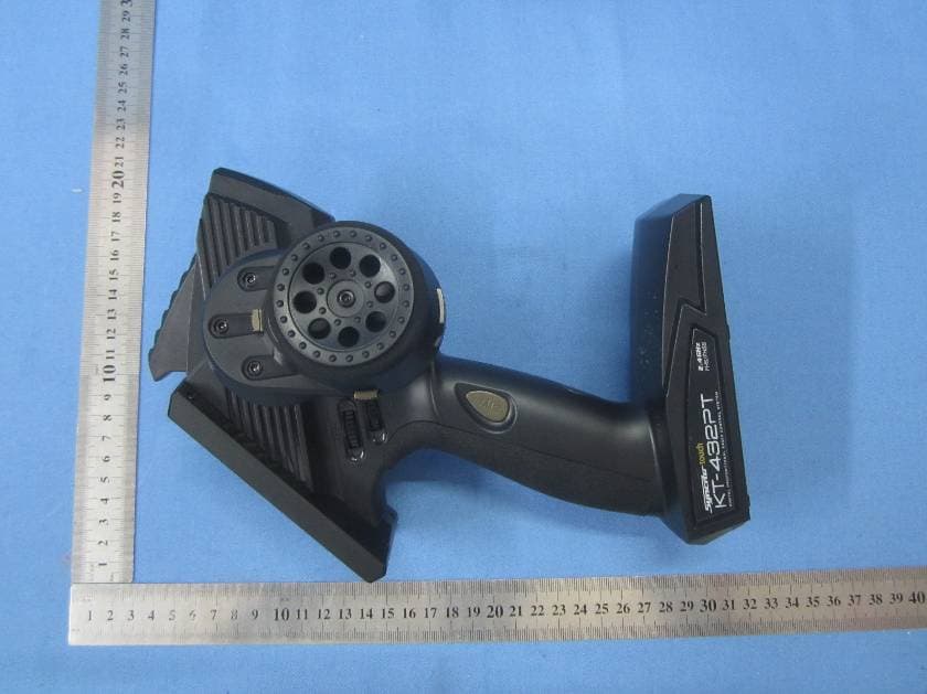
WIZKT432P
Aug 30, 2015DIGITAL PROPORTIONAL RADIO CONTROL SYSTEM
Equipment Class
DSS - Part 15 Spread Spectrum Transmitter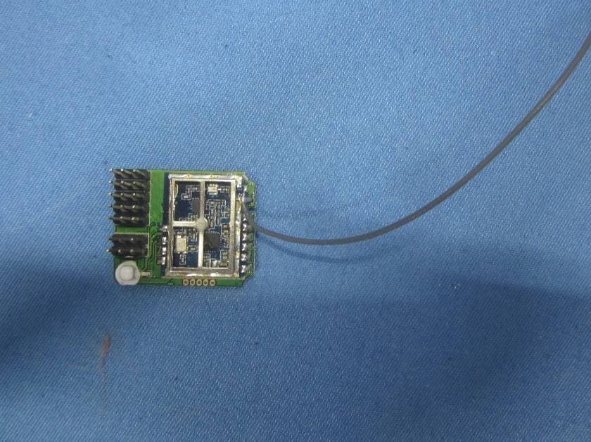
WIZKR431T
Aug 30, 2015DIGITAL PROPORTIONAL RADIO CONTROL SYSTEM
Equipment Class
DSS - Part 15 Spread Spectrum Transmitter
WIZKT331P
Mar 03, 20153-CHANNEL RADIO
Equipment Class
DSS - Part 15 Spread Spectrum Transmitter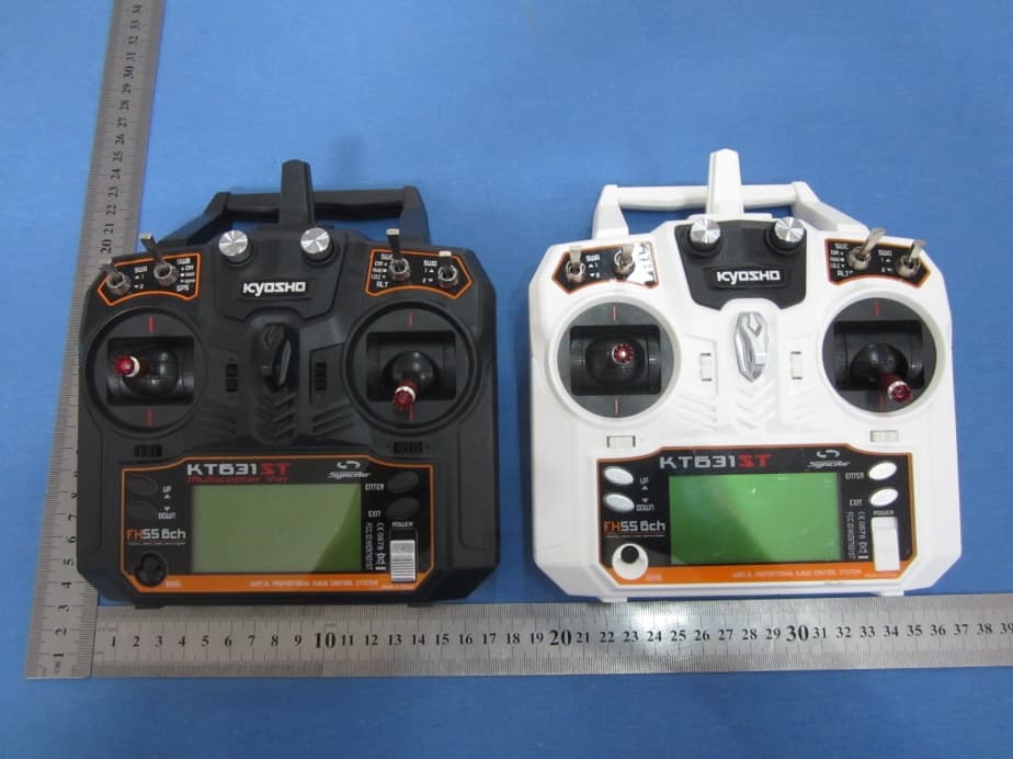
WIZKT631ST
Dec 01, 2014Digital proportional radio control system
Equipment Class
DSS - Part 15 Spread Spectrum Transmitter