WKX-MR302.4g reader
SHENZHEN MARKTRACE CO., LTD.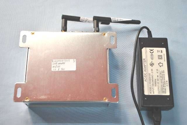
Click to zoom
Application Details
- Equipment Class
- DXT - Part 15 Low Power Transceiver, Rx Verified
- Date of Grant
- Dec 21, 2010
- Application Purpose
- Original Equipment
- Date of Application
- Dec 21, 2010
- Equipment Note
- 2.4g reader
- Frequency Range
- 2480.00000000 - 2480.00000000
- Company
- SHENZHEN MARKTRACE CO., LTD.
- Country
- China
Documents & Files
Document Text
Text extracted from the exhibit documents filed with the FCC. Open a document above to read the original.
Users Manual
MR30 2.4G Reader User Manual Catalog Chapter1 Short Introduction .............................................................................................................. 1 1.1 The appearance ................................................................................................................ 1 1.2 Introduction ...................................................................................................................... 1 1.3 The application ................................................................................................................. 1 1.4 MR30 reader main function ............................................................................................. 2 1.5 Specification..................................................................................................................... 2 Chapter2 MR30 reader full function demo ....................................................................................... 3 2.1 Connect reader ................................................................................................................. 3 2.2 Reset reader ...................................................................................................................... 6 2.3 Multi-tag Identify ............................................................................................................. 6 2.4 Configure the tag‟s sending time interval and sending power ......................................... 7 2.5 Tag operation .................................................................................................................... 8 2.6 Tag working mode instruction........................................................................................ 10 Chapter 3 MR30 reader application system .................................................................................... 11 3.1 System structure ............................................................................................................. 11 3.2 Working process instruction ........................................................................................... 11 Chapter 4 Second development ....................................................................................................... 12 Chapter1 Short Introduction 1.1 The appearance 1.2 Introduction MR30 is a 2.4GHz bi-directional antenna reader, it can write data to tag and meanwhile receive the data from tag. Both of the antenna are omni-directional, one is for RX and the other is for TX, so it can receive the signal from every direction. It supports TCP/IP and RS232 connection and very convenience for users to use. Mainly used in personal management or register system, etc. It can be matched with 2.4GHz tag that we supply to use. 1.3 The application MR30 reader always applies in the omni-directional identify system which need a wide passing channel, long range reading, fast identify, multi-tag identify, person‟s tracking and location field. ● Access management: open door control access management system, such as smart living district, car parking system, freeway ETC system, sea port and customs safety-inspection system. ●Personnel management: attendance administration management, conference signature system, student safety SMS system and even security patrol system. ●Goods management: warehouse goods management, data connection, moving goods monitor system, sea port goods automatically identify, registration management .etc ●prevent accident system: coal mine personnel management, manage the works and to avoid the big accident, anti-stolen management system. ●public traffic system: city traffic smart platform and car monitor ●Manufacture management: product workshop procedure management, monitor the production procedure ●Transportation management: road, railway management and the transportation flow, monitor and tracking of Container. 1.4 MR30 reader main function ●Write data to tag and receive data from tag, so called read & write reader. ●The communication between reader and tag is one-to-one, one tag marks one person or goods, tag ID is unique. ●Matched with MR3820A tag (read & write) to use, this reader can wake up MR3820A tag, after woken up, tag will send its ID to reader and then reader will transfer the tag ID to PC for users to observe. Reader will know a general position of the tag. ●Location: the reader can identify the tag within a circle (minimum radius is 3m and max is 80m), and the signal sent from reader is omni-directional. 1.5 Specification Model No. MR30 Frequency RX frequenc y: 2.44GHz TX frequenc y: 2.48GHz (sending an d receiving independent) Commun ica tion mode Dyn a mic encr yp t mode communica tion speed 9600Bps-115200Bps Signal modula tion mode GFSK Working mode Read,Write tag Error correction CRC8 Receiving s ensitivity -90dbm Iden tif y mod e Omni-directional, read with a radius 80m maximum circle,(custom to connect with directional antenna) Iden tify d is tance Maximum 80m(adjustable) Iden tif y sp eed 80km /h Anti-co llis ion Iden tif y mo re than 100 c ards a t the sa me time Error ra te 1:10000000 Voice indication Buzzer built-in Develop ing por t Supply all usab le de ve lo ping func tion Data interface Standard:RS232, and RJ45 Customized:WIFI or other Power supply DC+9V~+12V Work Temperature. -40°C~+85°C Size 160mm*120mm*35mm Chapter2 MR30 reader full function demo We supply 2.45GDemo.exe program to show the readers function; Open this software, this software support Chinese and English access, here we choose English to enter the software. Show the main operation interface: 2.1 Connect reader First make sure to connect the TX and RX antennas. This reader supply Ethernet port and serial port for communication and transferring the data, we supply demo software to show the reader‟s full function. Filter the repeated tag ID Counting the tag ID Continuous tag read display IP Address parameter set Com connection: If you use com port to connect the rea…
Text truncated - open the document above for the full version.
Block Diagram
MR30 (reader) block diagram RF transceiver IC nRF24L01(TX function) RF match circuit 16MHz oscillator SPI Atmega8 MCU RF transceiver IC nRF24L01(RX function) RF match circuit 16MHz oscillator ARM IC LPC2364 DM9161A SP3232E Ethernet port RS232 port SPI communication SPI control Buzzer LED Oscillator 12MHZ Eeprom FM25L256 Serial port communication TX antenna RX antenna
Cover Letter(s)
SHENZHEN MARKTRACE CO.,LTD. F3,Bldg,D,Changyuan New Meterial Port, Keyuan Rd,Science & Industry Park,Nanshan District,Shenzhen,China To: SIEMIC, INC. 2206 Ringwood Avenue, San Jose, CA 95131 USA Dear Sir/Madam, Re: Project and Product Certification Representative Authorization Letter We, SHENZHEN MARKTRACE CO.,LTD. hereby authorize SIEMIC, INC. to act as a Certification Body for certifying for the following project(s): Product description: 2.4g reader Model name: MR30, MR3001A, 3002A, MR3005, MR5100A, MR5002A FCC ID: WKX-MR30 We affirm that between SIEMIC and SHENZHEN MARKTRACE CO.,LTD. any difference in understanding, including test plan, measurement methods, applicable standards and relevant procedures and processes have been resolved prior to commencement of testing activities. Sincerely, GAOJUN/ Manager 12/16/2010
Cover Letter(s)
SHENZHEN MARKTRACE CO.,LTD. F3,Bldg,D,Changyuan New Meterial Port, Keyuan Rd,Science & Industry Park,Nanshan District,Shenzhen,China Federal Communications Commission 7435 Oakland Mills Road Columbia, MD Date: December 16, 2010 SUBJECT: FCC Application for FCC ID: WKX-MR30 To Whom It May Concern: This letter is to ascertain that SHENZHEN MARKTRACE CO.,LTD. Product has been the units used for conducting FCC compliance testing, the DoC part will be tested by FCC recognized test lab. If you have any question or concerns, please contact us Regards, GAOJUN/ Manager
External Photos
EUT top view EUT bottom view
ID Label/Location Info
This device complies with Part 15 of the FCC Rules. Operation is subject to the following two conditions: (1) this device may not cause harmful interference, and (2) this device must accept any interference received, including interference that may cause undesired operation. The Label must not be a stick-on paper label. The Label on these products must be permanently affixed to the product and readily visible at the time of purchase and must last the expected lifetime of the equipment not be readily detachable. FCC ID: WKX-MR30
ID Label/Location Info
Proposed Label Location on EUT EUT Bottom View/Proposed FCC ID Label Location
Internal Photos
EUT inside whole view Main&RF board component side Main&RF board solder side
Operational Description
1 Description: 1. RX antenna receive the RF signal of tag, nRF24l01 decode the data of tag, and send the data to ARM IC LPC2364 via SPI . LPC2364 check the data is ok, and send the data to RS232 port or Ethernet port. And flash red LED or driver buzzer 2. The SP3232E is interface circuit of RS232 . The DM9161A is interface circuit of Ethernet . 3. LPC2364 send data to MCU Atmega8 via serial port. MCU Atmega8 send data to nRF24L01 via SPI. nRF24L01 encode data to FSK and send the 2.4ghz FSK signal radio frequency to air from antenna. 4. FM25l256 is EEPROM. It store the data Note: The EUT's modulation mode is GFSK and has two antennas. The one is for transmit antenna and the other one is receiver antenna only. It's not multiple input & multiple output.
Schematics
2.4G Reader Marktrace C 12 REV: SIZE: CODE: DRAWN: DATED: DATED: CHECKED:QUALITY CONTROL: DATED: DATED: RELEASED: COMPANY:TITLE: DRAWING NO: SHEET: OF SCALE: REVISION RECORD APPROVED: ECO NO: LTR DATE: 1 2 3 4 5 6 DCBA CDBA 1 TDO 2 TDI 3 TMS 4 /TRST 5 TCK 6 P0.26 7 P0.25 8 P0.24 9 P0.23 10 VDDA 11 VSSA 12 VREF 13 VDCDC 14 RSTOUTN 15 VSS 16 RTCX1 17 /RESET 18 RTCX2 19 VBAT 20 P1.31 21 P1.30 22 X1 23 X2 24 P0.28 25 P0.27 26 P3.26 27 P3.25 28 VDD 29 P0.29 30 P0.30 31 VSS 32 P1.18 33 P1.19 34 P1.20 35 P1.21 36 P1.22 37 P1.23 38 P1.24 39 P1.25 40 P1.26 41 VSS 42 VDCDC 43 P1.27 44 P1.28 45 P1.29 46 P0.0 47 P0.1 48 P0.10 49 P0.11 50 P2.13 51 P2.12 52 P2.11 53 P2.10 54 VDD 55 VSS 56 P0.22 57 P0.21 58 P0.20 59 P0.19 60 P0.18 61 P0.17 62 P0.15 63 P0.16 64 P2.9 65 P2.8 66 P2.7 67 P2.6 68 P2.5 69 P2.4 70 P2.3 71 VDD 72 VSS 73 P2.2 74 P2.1 75 P2.0 76 P0.9 77 P0.8 78 P0.7 79 P0.6 80 P0.5 81 P0.4 82 P4.28 83 VSS 84 VDCDC 85 P4.29 86 P1.17 87 P1.16 88 P1.15 89 P1.14 90 P1.10 91 P1.9 92 P1.8 93 P1.4 94 P1.1 95 P1.0 96 VDD 97 VSS 98 P0.2 99 P0.3 100 RTCK U1 LPC23XX C10.1u R1 10k 1 AVDDR 2 AVDDR 3 RX+ 4 RX- 5 AGND 6 AGND 7 TX+ 8 TX- 9 AVDDT 10 PWRDWN 11 LED0/OP0 12 LED1/OP1 13 LED2/OP2 14 CABLESTS 15 DGND 16 TXER/TXD4 17 TXD3 18 TXD2 19 TXD1 20 TXD0 21 TXEN 22 TXCLK 23 DVDD 24 MDC 25 MDIO 26 RXD3 27 RXD2 28 RXD1 29 RXD0 30 DVDD 31 LEDMODE 32 MDINTR 33 DGND 34 RXCLK 35 CRS 36 COL 37 RXDV 38 RXER 39 DISMDIX 40 RESET 41 DVDD 42 XT2 43 XT1 44 DGND 45 NC 46 AGND 47 BGRESG 48 BGRES U2 DM9161A R2 10k R3 10k R4 10k R5 6.2k R6 6.2k 1 2 3 4 Y1 OSC5X7 R7 500 1 CS 2 SO 3 WP 4 GND 5 SI 6 SCK 7 HOLD 8 VCC U103 FM25L256 1 2 R110 10k 1 2 R111 10k C200.1u 1 2 Y3 C80.1u C9 0.1u C100.1u C110.1u C12 0.1u C13 0.1u C140.1u C150.1u C1633p C1733p 123 4 5678 13 14 15 16 J8 RJ45 C23 100p C24 100p R11 50 R12 50 R13 50 R14 50 C250.1u C260.1u C270.1u C280.1u C290.1u 1 2 Y4 C3022p C3122p 12 U16 BAT R22 10k J14-1J14-2 12 L5 IND0603 10uH C450.1u C460.1u + C47 + C48 C490.1u C500.1u 1 2 D1 LED0805 1 2 D3 LED0805 1 2 D5 LED0805 R29 1k R30 1k R31 200 R32 100 R33 100 VDD3.3 VDD3.3 VDD3.3 VDD3.3 VDD3.3 VDD3.3 VDD3.3 RXD0 TXD0 ENET_TXD0 ENET_TXD1 ENET_TX_EN ENET_CRS ENET_RXD0 ENET_RXD1 ENET_RX_ER ENET_REF_CLK ENET_MDC ENET_MDIO RST RST TCK TRST TMS TDI TDO RTCK E_RX+ E_RX- E_TX- E_TX+ LED_LINK LED_SPEED LED_ACT ENET_TXD1 ENET_TXD0 ENET_TX_EN VDD3.3 ENET_MDC ENET_MDIOENET_RXD1ENET_RXD0 VDD3.3 VAA3.3 VAA3.3 ENET_CRS ENET_RX_ER VDD3.3 ENET_RST ENET_REF_CLK ENET_REF_CLK VDD3.3 SPI_MISO SPI_SCK SPI_NSS SPI_MOSI VDD3.3 VDD3.3 VDD3.3 E_TX+ E_TX- E_RX+ E_RX- VAA3.3 E_RX+ E_RX- E_TX+ E_TX- ENET_RSTLED1LED2LED3LED4 VBAT VDD3.3 VBAT TXD2 RXD2 RS485EN IO4FINTIO0IO1IO2IO3ISP ISP VDD3.3 VDD3.3 VAA3.3 SPI_SCKSPI_NSSSPI_MISOSPI_MOSI MOSI1 MISO1 SCK1 CSN CE VDD3.3 LED_ACT LED_LINK VDD3.3 LED1 LED2 VDD3.3 BUZZERW0W1 Marktrace 2.4G Reader C 22 REV: SIZE: CODE: DRAWN: DATED: DATED: CHECKED:QUALITY CONTROL: DATED: DATED: RELEASED: COMPANY:TITLE: DRAWING NO: SHEET: OF SCALE: REVISION RECORD APPROVED: ECO NO: LTR DATE: 1 2 3 4 5 6 DCBA CDBA J7-1J7-2J7-3J7-4J7-5J7-6J7-7J7-8J7-9 1 RO 2 RE 3 DE 4 DI 5 GND 6 A 7 B 8 VCC U18 MAX487E R210 120 C206 0.1uF C202 0.1u C203 0.1u C204 0.1u C205 0.1u C201 0.1u 16 VCC 2 V+ 6 V- 15 GND 14 T1OUT 13 R1IN 7 T2OUT 8 R2IN 1 C1+ 3 C1- 4 C2+ 5 C2- 11 T1IN 12 R1OUT 10 T2IN 9 R2OUT U102 SP3232E E B C Q101 1 2 R106 100 1 2 R107 10 1 + 2 - U15 BUZZER C3080.1u 3 VIN 1 GND 2 VOUT U13 SPX1117M3 L301 C3100.1uF + C32 + C33 J13-1J13-2J13-3 1 V1 VIA 1 V3 VIA 1 V4 VIA 1 V7 VIA 12 L6 IND0603 10uH C440.1u D302 + C302 10uF 1 IN 2 GND 3 OUT U21 L7805 + C306 10uF D301 C301 C305 R8 ??? R9 ??? R34 100 R35 100 R36 N/A R37 N/A 123 4 X3 1 CE 2 CSN 3 SCK 4 MOSI 5 MISO 6 IRQ 7 VDD 8 VSS 9 XC2 10 XC1 11 VDD_PA 12 ANT2 13 ANT1 14 VSS 15 VDD 16 IREF 17 VSS 18 VDD 19 DVDD 20 VSS NRF24L01PT C215pF C715pF C32.2pF C44.7pF C5 1.5pF C61.0pF C18 0.1u C19 0.1u C2110u 1 2 R10 1M 1 2 R15 22K 12 L1 8.2N 12 L2 2.7N 12 L3 3.9N 5 J3 J-SMA 1 2 R26 10K 1 2 R27 10K 1 2 R28 10K C5210p C5310P C5410P J1-1 J1-2J1-3J1-4J1-5J1-6 J1-7J1-8J1-9 J1-10J1-11J1-12J1-13J1-14 J1-15 R16 10k R17 10k + C2210uF R18 10k 1 2 D2 LED0805 1 2 D4 LED0805 R19 10k R20 10k 1 2 147 U3-A 7404 3 4 U3-B 7404 C340.1u J2-1J2-2J2-3 A+B- VDD5.0 RS485EN TXD2 RXD2 232-RXD 232-TXD RXD0TXD0 VDD3.3 BUZZER VDD3.3 +5V VDD3.3 232-RXD 232-TXD POWER_IN +5V VDD5.0 A+ B- MOSI1 MISO1 SCK1 VDD3.3 VDD3.3 VDD3.3 VDD3.3 CE CSN SCK1 MOSI1MISO1 FINT TXD2 RXD2 VDD5.0 VDD5.0 VDD5.0 W0 W1
Test Report
The test report consists 25 pages in total. It may be duplicated completely for legal use with the allowance of the applicant. It shall not be reproduced except in full, without the written approval of Ke Mei Ou Laboratory Corporation. The test result in the report only applied to the tested sample. FCC TEST REPORT Under FCC 15 Subpart C, Paragraph 15.249 Prepared For : SHENZHEN MARKTRACE CO.,LTD. F3,Bldg,D,Changyuan New Meterial Port, Keyuan Rd,Science & Industry Park,Nanshan District,Shenzhen,China FCC ID: WKX-MR30 EUT: 2.4G Reader Model: MR30 December 16, 2010 Issue Date: Original Report Report Type: Test Engineer: Jacky Huang Review By: Apollo Liu / Manager Ke Mei Ou Laboratory Co., Ltd. 7A, Jiaxiangge, Jiahuixincheng, No.3027, Shennan Rd., Futian, Shenzhen, Guangdong, P.R.China. Zip Code: 518033 Tel: + 86 755 83642690 Fax: + 86 755 83297077 www.kmolab.com SHENZHEN MARKTRACE CO.,LTD. FCC ID: WKX-MR30 KMO FCC ID Report Report #: KSZ2010101503J01 Page 2 of 25 TABLE OF CONTENTS 1. General Information............................................................................................................................................................ 3 1. 1 Notes ............................................................................................................................................................................... 3 1. 2 Testing Laboratory .......................................................................................................................................................... 3 1. 3 Details of Applicant ........................................................................................................................................................ 3 1. 4 Application Details ......................................................................................................................................................... 3 1. 5 Test Item ......................................................................................................................................................................... 3 1. 6 Test Standards ................................................................................................................................................................. 3 2. Technical Test ....................................................................................................................................................................... 4 2. 1 Summary of Test Results ................................................................................................................................................ 4 3. EUT Modifications .............................................................................................................................................................. 4 4. Conducted Power Line Test ................................................................................................................................................ 5 4. 1 Test Equipment ............................................................................................................................................................... 5 4. 2 Test Procedure ................................................................................................................................................................ 5 4. 3 Test Setup ....................................................................................................................................................................... 5 4. 4 Configuration of the EUT ............................................................................................................................................... 6 4. 5 EUT Operating Condition ............................................................................................................................................... 7 4. 6 Conducted Power Line Emission Limits ........................................................................................................................ 7 4. 7 Conducted Power Line Test Result ................................................................................................................................. 7 5. Radiated Emission Test ....................................................................................................................................................... 9 5. 1 Test Equipment ............................................................................................................................................................... 9 5. 2 Test Procedure ................................................................................................................................................................ 9 5. 3 Radiated Test Setup ........................................................................................................................................................ 9 5. 4 Configuration of the EUT ............................................................................................................................................. 10 5. 5 EUT Operating Condition ............................................................................................................................................. 10 5. 6 Radiated Emission Limit .............................................................................................................................................. 10 5. 7 Radiated Emission Test Result ...................................................................................................................................... 11 6. Band Edge .......................................................................................................................................................................... 13 6. 1 Test Equipment ......................................................................................................................................…
Text truncated - open the document above for the full version.
Test Setup Photos
Conducted emission test view Radiated emission test view
Contact Information
Applicant
Gao Jun(Manager)
Test Firm
SinTek Laboratory Co., Ltd.Eric Lin
Technical Specifications
| # | Rule Parts | Frequency Range | Power Output |
|---|---|---|---|
| 1 | 15C | 2.48 GHz - 2.48 GHz | - |
Other Applications from SHENZHEN MARKTRACE CO., LTD.

WKX-MR3848
May 07, 20152.4G Active RFID Tag
Equipment Class
DXX - Part 15 Low Power Communication Device Transmitter
WKX-MR38
Dec 19, 20102.4G Tag
Equipment Class
DXT - Part 15 Low Power Transceiver, Rx Verified