WM7CONFIDEAWDUG3Wireless Conference System (delegated unit)
Televic NV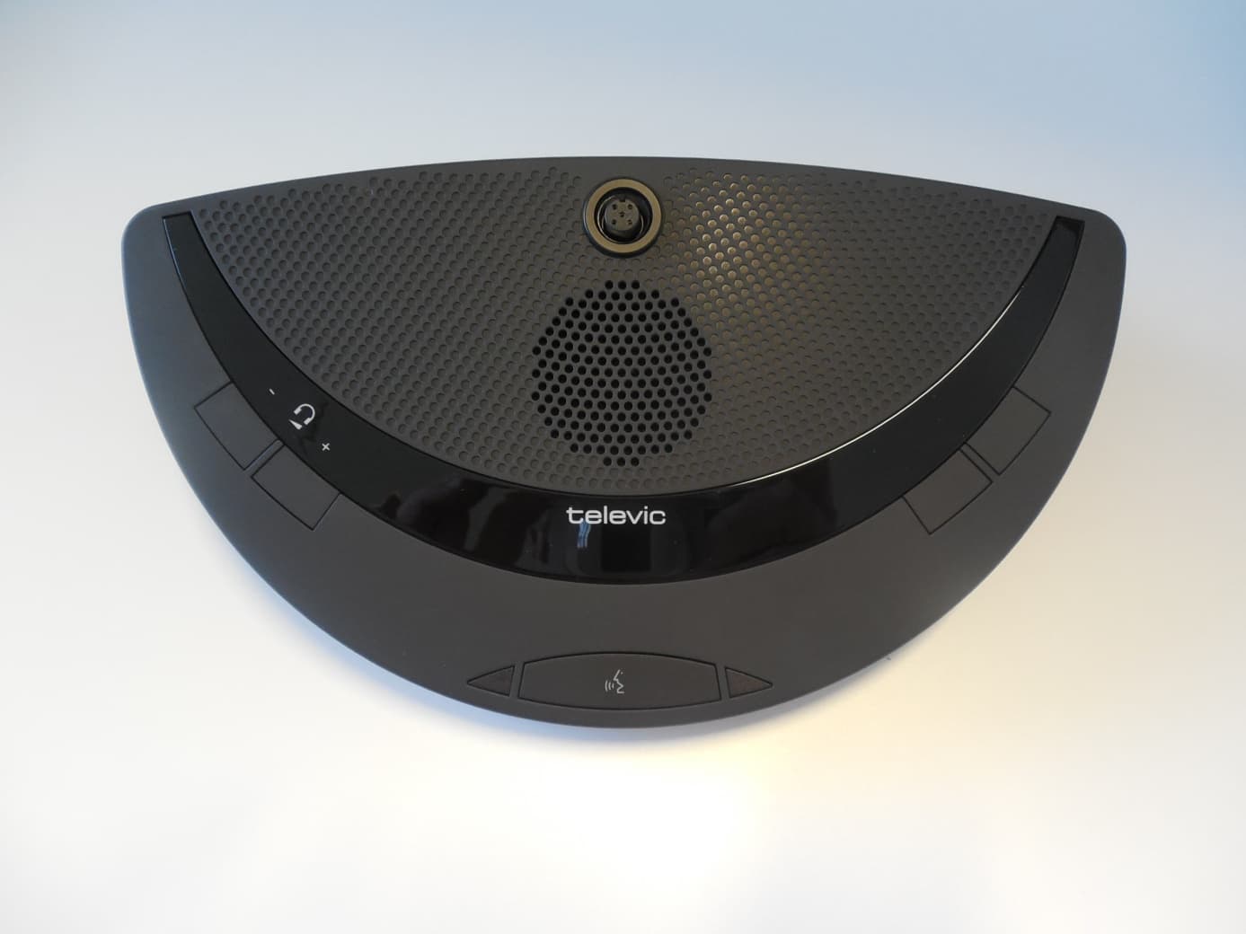
Click to zoom
Application Details
- Equipment Class
- NII - Unlicensed National Information Infrastructure TX
- Date of Grant
- Jul 12, 2015
- Application Purpose
- Original Equipment
- Date of Application
- Jul 12, 2015
- Equipment Note
- Wireless Conference System (delegated unit)
- Frequency Range
- 5745.00000000 - 5850.00000000
- Company
- Televic NV
- Country
- Belgium
Documents & Files
Document Text
Text extracted from the exhibit documents filed with the FCC. Open a document above to read the original.
Users Manual
confidea Installation & User manual Attention: This manual for Wireless Confidea System 3.0 is valid only for all WCAP+ firmware version ≥ 1.06 WCAP fpga version ≥ 1.06 WDU+ firmware version ≥ 1.06 WCAP+ 71.98.0033 Cocon ≥ 3.02 01 General information 1 Copyright Statement 4 2 Trademarks 5 4 1 Copyright Statement No part of this publication or documentation accompanying this product may be reproduced in any form or by any means or used to make any derivative such as translation, transformation, or adaptation without the prior written permission of the publisher, except in case of brief quotations embodied in critical articles or reviews. Contents are subject to change without prior notice. Copyright© 2008 by Televic Conference NV. All rights reserved. The authors of this manual have made every effort in the preparation of this book to ensure the accuracy of the information. However, the information in this manual is supplied without warranty, either express or implied. Neither the authors, Televic Conference NV, nor its dealers or distributors will be held liable for any damages caused or alleged to be caused either directly or indirectly by this book. 2 Trademarks 5 2 Trademarks All terms mentioned in this manual that are known to be trademarks or service marks have been appropriately capitalized. Televic NV cannot attest to the accuracy of this information. Use of a term in this book should not be regarded as affecting the validity of any trademark or service mark. 6 3 Contents 1 Copyright Statement 4 2 Trademarks 5 4 How to connect 8 4.1 Power up 8 4.2 Accessing the web-browser 8 4.3 Login wizard 8 4.4 Introduction 8 First time access 8 4.5 Return to factory settings 11 5 Web server 12 5.1 Compatibility 12 5.2 Navigating through the webserver 13 5.3 Changing IP address 14 5.4 Initialization 16 5.4.1 Controlled Access 16 5.5 Unit Manager 17 5.5.1 Define groups 18 5.5.2 Define delegate names and assign to group 18 5.5.3 Remove delegate 19 5.5.4 Visualize delegate names or numbers in unit manager 19 5.6 Unit monitoring 20 5.7 Activating microphones 21 5.8 Conference options 21 5.8.1 Max active microphones 21 5.8.2 Microphone modes 22 5.8.3 Microphone preset 23 5.9 AUX Control 24 5.9.1 AUX In/out 24 5.9.2 General Aux settings - Audio routing 24 5.10 Regional settings 26 5.11 Security 26 2 Trademarks 7 5.12 Check firmware versions of delegate units 27 5.13 Check firmware versions of WCAP 28 5.14 Update 28 5.14.1 WCAP update 29 5.14.2 Update delegate units 31 6 Frequency selection 32 6.1 Check already used frequencies by other Confidea G3 systems 32 6.2 Selecting own frequencies 32 6.3 The current used frequency 33 6.4 Frequencies used by other Confidea G3 systems 33 6.5 Other indications 33 6.5.1 Signal quality 33 6.5.2 Sorting frequencies 33 7 Message screen 34 8 Guidelines on optimal WCAP setup and configuration 35 8.1 Positioning the Confidea Wireless Access Point 35 8.2 Optimizing the position the antennas 35 8.3 Max range of WCAP 36 9 Frequency Planning 37 9.1 Use with WiFi base stations nearby 37 9.2 Avoiding interference b.m.o. wifi collection points 37 10 Adding Cocon license to the WCAP 38 10.1 Introduction 38 10.2 Get the MAC address of your central equipment 38 10.3 Upload your license file 39 11 Appendix 40 11.1 Use of camera control feature 40 11.1.1 Overview 40 11.1.2 Connectivity 40 11.1.3 Commands for Confidea Gen III camera protocol 40 02 4 How to connect 4.1 Power up After applying the 24V adapter to the power supply socket and switching the device on, the first LED blinks white. This means the system is booting. Note: If the LED does not switch to green after some minutes or it turns red, please contact your support team. 4.2 Accessing the web-browser To access the web-browser connect the LAN connector directly to your computer or to the LAN network which includes your computer. The default IP address is 192.168.1.110. Please make sure that your PC has an IP address and subnet mask that can access that IP address. 4.3 Login wizard When you enter the web-browser for the first time you will be guided through a small wizard for initial setup of the system. 4.4 Introduction The WCAP has a built-in web server that allows you to set/monitor certain parameters characterizing the wireless conference system. The following is a step-by-step guide to give you a general idea of how to access your WCAP. First time access STEP 1 – PC IP setup In order to access the built-in web server for the first time, the TCP IP settings from the PC or MAC must be modified. A fixed IP address has to be set. Therefore follow the instructions below. Note: The WCAP has a default fixed IP address and subnet mask: IP: 192.168.1.110 Subnet mask: 255.255.255.0 4 How to connect 9 - Gotothe‘ControlPanel’ - Click on Network and sharing center - Click on Change adapter settings - Right-click on Local Area Connection - Double on Properties - Click on Internet Protocol (TCP/IP) - Click Properties Static IP address WINDOWS 7 - Input your IP Address and subnet mask the IP addresses on the network must be within the same range. - The default IP address from the WCAP is 192.168.1.110 so the computer should have an IP Address that is within the same subnet, like 192.168.1.11 and 192.168.1.20. The subnet mask must be the same for all equipment on the network: 255.255.255.0) - Click OK Assigning a fixed IP Address in WINDOWS 7 - Enter the IP Settings op the PC - InthisexamplethePChasnormally“10.0.40.85” as IP address. - Click on Advanced and add a new IP address that is in the range of the access point, for example 192.168.0.26 and subnet mask 255.255.0.0 - Click to add 10 - Click OK STEP 2 - Accessing WCAP Open Internet Explorer or any other browser (with the computer connected to the WCAP) Enter 192.168.1.110 or wcap3.local into the Address Bar, press Enter A wizard will guide you through the initial system setup: - Choose your language - Then you can choose to be notified when updates are available.…
Text truncated - open the document above for the full version.
RF Exposure Info
RF EXPOSURE EVALUATION Equipment under test: CONFIDEA DVG3 Test report reference: RC-030-GTE-14-105110-6-A MPE calculation These equations are generally accurate in the far field of an antenna but will over predict power density in the near field, where they could be used for making a “worst case” prediction. S = PG/4πR² Where: S = power density (in appropriate units, e.g. mW/cm²) P = power input to the antenna (in appropriate units e.g. mW) G = power gain of the antenna in the direction of interest relative to the isotropic radiator R = distance to the centre of radiation of the antenna (appropriate units e.g. cm) Or S = EIRP/4πR² Where EIRP = equivalent isotropically radiated power Calculation: (Calculated for max. EIRP) EIRP: 12.6 dBm (18.20 mW) Calculated at distance of 20 cm: Power density = 0.003620 mW/cm² Limit: 1mW/cm² is the reference level for general public exposure according to the OET Bulletin 65. Edition 97-01 Table1 Siège Social : Emitech - 3, rue des Coudriers - Z.A. de l’Observatoire - 78180 MONTIGNY LE BX - France Siret : 344 545 645 00022 - Tél. : 33 (0)1 30 57 55 55 - Fax : 33 (0)1 30 43 74 48 - E-mail : [email protected] - URL : www.emitech.fr S.A. au capital de 1 560 000 € - R.C.S. VERSAILLES 344 545 645 - APE 7112B
Test Report
RC-030-GTE-14-105110-6-A (01) Page 2 out of 51 TEST CERTIFICATION FOR: FCC Certification NAME OF THE EQUIPMENT UNDER TEST: Microphone Type: CONFIDEA DV G3 Serial number: 134101215110000 Reference / model (P/N): 71.98.0006 Software version: - NAME OF THE MANUFACTURER: TELEVIC ADDRESS OF THE APPLICANT: Company: TELEVIC Address: Leo Bekaertlaan 1 8870 Izegem BELGIUM Person in charge: Mr DUMEZ DATES OF TESTS: From 03/10/2014 to 20/10/2014 and 25/02/2015 TESTS LOCATION: Open area test site in Aunainville (28) - FRANCE TESTS OPERATOR: F. LHEUREUX RC-030-GTE-14-105110-6-A (01) Page 3 out of 51 TABLE OF CONTENTS 1. INTRODUCTION ____________________________________________________________________ 4 2. REFERENCES DOCUMENTS _________________________________________________________ 4 3. PRODUCT DESCRIPTION ____________________________________________________________ 5 4. TESTS AND CONCLUSION ___________________________________________________________ 6 5. 6 dB BANDWIDTH 26, dB BANDWIDTH AND 99 % OCCUPIED BANDWIDTH ___________________ 9 6. MAXIMUM OUTPUT POWER _________________________________________________________ 14 7. PEAK POWER SPECTRAL DENSITY __________________________________________________ 17 8. PEAK EXCURSION RATIO ___________________________________________________________ 20 9. ADDITIONAL PROVISIONS TO THE GENERAL RADIATED EMISSIONS LIMITATION ___________ 23 10. BAND EDGE ______________________________________________________________________ 25 11. UNINTENTIONAL RADIATED EMISSIONS AND TRANSMITTER UNWANTED EMISSION IN THE BAND 9 KHz – 40 GHz ______________________________________________________________ 27 12. RADIATED EMISSION LIMIT _________________________________________________________ 31 ANNEX 1: ANTENNA FACTORS, INSERTION LOSSES AND AMPLIFIER VALUES ANNEX 2: EXTERNAL PHOTOGRAPHIES ANNEX 3: TEST SETUP PHOTOGRAPHIES ANNEX 4: CALIBRATION DATES RC-030-GTE-14-105110-6-A (01) Page 4 out of 51 1. INTRODUCTION This document presents the results of Electromagnetic Compatibility tests performed on the equipment « Microphone type: CONFIDEA DV G3» according to references documents listed below. 2. REFERENCES DOCUMENTS FCC 47 CFR Part 15: 2014 Code of Federal Regulations Title 47- Telecommunication Chapter 1- Federal Communication Commission Part 15- Radio frequency devices ANSI C63.4: 2003 Methods of Measurement of Radio-Noise Emissions from Low-Voltage Electrical and Electronics Equipment in the range of 9 kHz to 40 GHz. 789033 D02 General UNII Test Procedures new rules v01 Guidelines for Compliance Testing of Unlicensed National Information Infrastructure (U-NII) Devices Part 15, Subpart E RC-030-GTE-14-105110-6-A (01) Page 5 out of 51 3. PRODUCT DESCRIPTION Class: B (residential environment) Antenna type and gain: Internal antenna: Not communicated Modulation: OFDM @ 54 Mbits/sec Power source: 7.2 Vdc Software power setting: The microphone is paired with the wireless conference access point system. (The power is not adjustable, only the channels) Operating frequency range: From 5150 MHz to 5250 MHz From 5725 MHz to 5825 MHz Operating mode: Slave device without radar detection¹ Table for carrier frequency: 802.11 a (20 MHz) Channel No. 36 40 44 48 149 153 157 161 CF (MHz) 5180 5200 5220 5240 5745 5765 5785 5805 Tested X X X X X X ¹ : The E.U.T. does not use the following frequencies bands: 5250 MHz to 5350 MHz 5470 MHz to 5725 MHz Modification of the equipment during the tests: No RC-030-GTE-14-105110-6-A (01) Page 6 out of 51 4. TESTS AND CONCLUSION The following tables summarize test results of the EUT. Subpart B of the standard FCC part 15 – Unintentional radiators Test procedure Designation of test Test results Comments Pass Fail N.A. N.P. 15.107 Measurement of conducted emission on AC mains ports X 15.109 Radiated emission limits X RC-030-GTE-14-105110-6-A (01) Page 7 out of 51 Subpart C of the standard FCC part 15 – Intentional radiators Test procedure Designation of test Test results Comments Pass Fail N.A. N.P. 15.205 Restricted bands of operation X 15.207 Measurement of conducted emission on AC mains ports X 15.209 Radiated emission limits; general requirements X 15.215 Additional provisions to the general radiated emission limitations (a) Alternative to general radiated emission limits X (b) Unwanted emissions outside of § 15.247 frequency bands X (c) 20 dB bandwidth and band-edge compliance X 15.407 Intentional radiated emissions a) Power limits a) (1) in the bands 5150–5250 MHz - maximum conducted output power X - 26 dB bandwidth X - peak power spectral density X a) (2) in the bands 5250–5350 MHz and 5470- 5725 MHz - maximum conducted output power X - 26 dB bandwidth X - peak power spectral density X a) (3) in the bands 5725–5825 MHz - maximum conducted output power X - 6 dB bandwidth X - peak power spectral density X a) (6) peak excursion ratio X b) Undesirable emission limits b) (1) outside of the bands 5150–5250 MHz X b) (2) outside of the bands 5250–5350 MHz X b) (3) outside of the bands 5470-5725 MHz X b) (4) outside of the bands 5725–5825 MHz X c) Operation in the absence of information to transmit X g) Frequency Stability X h) Transmit Power Control (TPC) and Dynamic Frequency Selection (DFS) X h) (1) TPC operating in the bands 5250-5350 MHz and 5470-5725MHz X output power < 500mW h) (2) DFS operating in the bands 5250-5350 MHz and 5470-5725MHz X N.A.: Not Applicable N.P.: Not Performed RC-030-GTE-14-105110-6-A (01) Page 8 out of 51 Conclusion: The tested sample " Microphone type: CONFIDEA DV G3 " submitted to the tests complies with the requirements of the standard: FCC 47 CFR PART 15 : 2014 According to the limits specified in this report. RC-030-GTE-14-105110-6-A (01) Page 9 out of 51 5. 6 dB BANDWIDTH, 26 dB BANDWIDTH AND 99 % OCCUPIED BANDWIDTH Standard: FCC 47 CFR PART 15 : 2014 Sections: 15.407 a) (1) and (3) Test configuration: The system is tested in an open area test site (OATS). The test unit is placed on a rotating table, 0.8 m from a ground plane. Zero degr…
Text truncated - open the document above for the full version.
Contact Information
Applicant
Bart Deschodt(General manager)
Test Firm
EMITECH MontignyMaxime Michau
Technical Specifications
| # | Rule Parts | Frequency Range | Power Output |
|---|---|---|---|
| 2 | 15E | 5.75 GHz - 5.85 GHz | 10.00 mW |
Other Applications from Televic NV
WM7CONFIDEAWCAPG3
Jul 12, 2015Wireless Conference System (delegated unit)
Equipment Class
NII - Unlicensed National Information Infrastructure TX