WMXSRZ2100Wireless Siren
Sensing Tek Co., Ltd.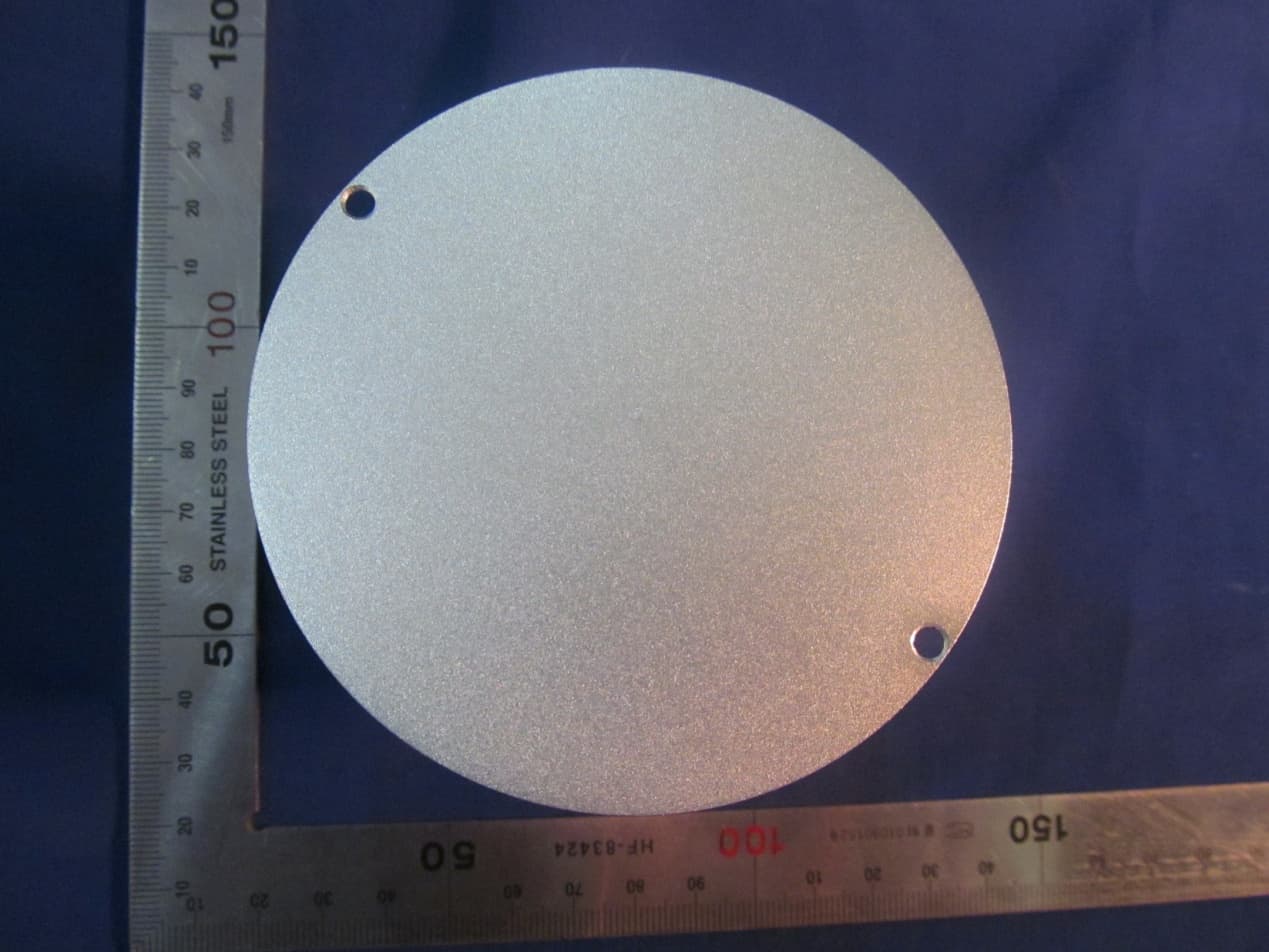
Click to zoom
Application Details
- Equipment Class
- DTS - Digital Transmission System
- Date of Grant
- Apr 15, 2015
- Application Purpose
- Original Equipment
- Date of Application
- Apr 15, 2015
- Equipment Note
- Wireless Siren
- Frequency Range
- 2405.00000000 - 2480.00000000
- Company
- Sensing Tek Co., Ltd.
- Country
- Taiwan
Documents & Files
Document Text
Text extracted from the exhibit documents filed with the FCC. Open a document above to read the original.
Users Manual
Wireless Siren user manual Mode: SRZ2100 Wireless alarm instructions First, Wireless alarm components: SRZ2100 X 1 AC adapter X 1 Changer line X 1 Wireless alarms add network description: 1, Wireless alarm installed in a prominent, easy to alert local. 2, Alarm wireless adapter (output 5V/2A ) Access. 3, The adaptor 120VAC Connected to the power mains, 12VDC Output connector to plug in the WI‐FI/ZigBee GateWay Back DC12V 。 4, Connect network cable WI‐FI/ZigBee GateWay Back LAN Interface, and the other end connected PC The network port. 5, Open IE Written on the address bar of the browser: 192.168.5.1 Click the Enter key to enter WI‐FI/ZigBee GateWay Login screen as shown below: 6, WI‐FI/ZigBee GateWay Login into your user name admin , Password 123456 , Sign in to the router. The following figure: 7, Click on the Site contents‐>ZigBee‐‐> Access Control The following figure: 8, If the new sensors join WI‐FI/ZigBee GateWay Successful displays like the one above, such as the join does not succeed then the power adapter, and then power on again. 9, NO Says how many sensors are successfully joined the network in the list, select the sensor data to the Tablet client ALLOW Tick to select: 10. the ZigBee Access Control interface, click on the Apply Changes button as shown below: 11. exit the WI‐FI/ZigBee GateWay settings, sensor back to electricity, you can display the newly added device Tablet client. FCC Statement This equipment has been tested and found to comply with the limits for a Class B digital device, pursuant to part 15 of FCC Rules. These limits are designed to provide reasonable protection against harmful interference in a residential installation. This equipment generates and can radiate radio frequency energy and, if not installed and used in accordance with the instructions, may cause harmful interference to radio communications. However, there is no guarantee that interference will not occur in a particular installation. If this equipment does cause harmful interference to radio or television reception, which can be determined by turning the equipment off and on, the user is encouraged to try to correct the interference by one or more of the following measures: --Reorient or relocate the receiving antenna. --Increase the separation between the equipment and receiver. --Connect the equipment into an outlet on a circuit different from that to which the receiver is connected. --Consult the dealer or an experienced radio/TV technician for help. This device complies with Part 15 of FCC Rules. Operation is subject to the following two conditions: (1) This device may not cause harmful interference, and (2) This device must accept any interference received, including interference that may cause undesired operation. Note: The manufacturer is not responsible for any radio or TV interference caused by unauthorized modifications to this equipment. Such modifications could void the user’s authority to operate this equipment. Any Changes or modifications not expressly approved by the party responsible for compliance could void the user's authority to operate the equipment. SAR Statement This device is measured RF output power is less than the SAR exclusion threshold value for human head and body. Therefore, SAR test is not necessary.
Cover Letter(s)
Sensing TeK Co., Ltd. Apr. 09, 2015 Federal Communications Commission Authorization and Evaluation Division FCC ID: WMXSRZ2100 Confidentiality Request Pursuant to Sections 0.457 and 0.459 of the Commission’s Rules, we hereby request confidential treatment of information applied this application as outlined below: Schematic Theory of Operation Block Diagram The above materials contain trade secrets and proprietary information not customarily released to the public. The public disclosure of these matters might be harmful to the applicant and provide unjustified benefits to its competitors. The Applicant understands that pursuant to Rule 0.457, disclosure of this Application and all accompanying documentation will not be made before the date of the Grant for this application Sincerely Signature Name: Hung Chang Chen Title: Director Tel: 886-3-5508383
External Photos
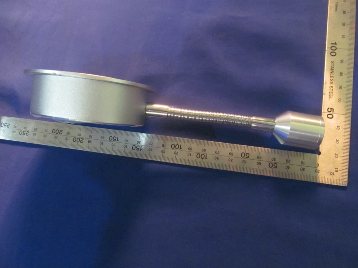
External Photo
ID Label/Location Info
Sensing TeK Co., Ltd. FCC ID:WMXSRZ2100
Internal Photos
Internal Photo
Test Report
Shenzhen Asia Test Technology Co., Ltd. 7 / F, Xinwei Building, Gushu Village, Xixiang Town, Baoan District, Shenzhen, China Tel: +86)‐0755‐23284990 Email: att@att‐lab.com Http: // www.att‐lab.cn Page 1of 29 FCC RF Test Report Product Type :Wireless Siren Report No :ATT-2015SZ0229147F-1 Applicant :Sensing TeK Co., Ltd. Address : 4F-1,No.62,Chen Gung 5 st., ChuBei City, Hsinchu county Taiwan 302 Trade Name :N/A Model Number : SRZ2100 List Model : N/A Test Specification : FCC 47 CFR PART 15 SUBPART C: Oct., 2013 ANSI C63.10:2009 KD558074 D01 DTS Meas Guidance v03r02 Receive Date :15 Feb,2015 Test Period :16 Feb ,2015 to 11 Mar , 2015 Issue Date :12 Mar , 2015 Issue by Shenzhen Asia Test Technology Co.,Ltd. 7 / F, Xinwei Building, Gushu Village, Xixiang Town, Baoan District, Shenzhen, China. Note: This report shall not be reproduced except in full, without the written approval of Shenzhen Asia Test Technology Co.,Ltd. This document may be altered or revised by Asia Institute Technology (Dongguan) Limited. Personnel only, and shall be noted in the revision section of the document. The client should not use it to claim product endorsement by TAF, or any government agencies. The test results in the report only apply to the tested sample. Shenzhen Asia Test Technology Co., Ltd. 7 / F, Xinwei Building, Gushu Village, Xixiang Town, Baoan District, Shenzhen, China Tel: +86)‐0755‐23284990 Email: att@att‐lab.com Http: // www.att‐lab.cn Page 2of 29 Certification of Compliance Issued Date: 12/03/2015 Product Type : Wireless Siren Applicant : Sensing TeK Co., Ltd. Address : 4F-1,No.62,Chen Gung 5 st., ChuBei City, Hsinchu county Taiwan 302 Manufacturer : Sensing TeK Co., Ltd. Address : 4F-1,No.62,Chen Gung 5 st., ChuBei City, Hsinchu county Taiwan 302 Trade Name : N/A Model Number : SRZ2100 List Mode N/A FCC ID : WMXSRZ2100 EUT Rated Voltage : DC 5.0V From Adapter Applicable Standard : FCC 47 CFR PART 15 SUBPART C: Oct., 2013 ANSI C63.10:2009 KD558074 D01 DTS Meas Guidance v03r02 Test Result : Complied Performing Lab. : Shenzhen Asia Test Technology Co.,Ltd. 7 / F, Xinwei Building, Gushu Village, Xixiang Town, Baoan District, Shenzhen, China The EUT described above is tested by Shenzhen Asia Test Technology Co.,Ltd. EMC Laboratory to determine the maximum emissions from the EUT. Shenzhen Asia Test Technology Co.,Ltd. EMC Laboratory assumed full responsibility for the accuracy of the test results. The test data, data evaluation, test procedures, and equipment configurations shown in this report were made in accordance with the procedures given in ANSI C63.4 (2003) and the energy emitted by the sample EUT tested as described in this report is in compliance with FCC Rules Part 15.207, 15.209 and 15.247. The test results of this report relate only to the tested sample identified in this report. Approved By : Reviewed By : (Testing Engineer) ( Seal Chen) (Manager) (Jackie Deng) Shenzhen Asia Test Technology Co., Ltd. 7 / F, Xinwei Building, Gushu Village, Xixiang Town, Baoan District, Shenzhen, China Tel: +86)‐0755‐23284990 Email: att@att‐lab.com Http: // www.att‐lab.cn Page 3of 29 CONTENT 1 GENERAL INFORMATION .................................................................................................................................... 4 1.1 APPLIED STANDARD .................................................................................................................................................. 4 1.2 TEST LOCATION ........................................................................................................................................................ 4 1.3 TEST ENVIRONMENT CONDITION ................................................................................................................................. 4 2 TEST SUMMARY ................................................................................................................................................. 4 3 DESCRIPTION OF THE EQUIPMENT UNDER TEST (EUT) ........................................................................................ 5 3.1 GENERAL DESCRIPTION .............................................................................................................................................. 5 3.2 EUT CONFIGURATIONS .............................................................................................................................................. 5 3.3 TEST ENVIRONMENTS ................................................................................................................................................ 6 3.4 TEST SETUPS ........................................................................................................................................................... 6 3.5 TEST CONDITIONS ..................................................................................................................................................... 8 4 MEASUREMENT UNCERTAINTY .......................................................................................................................... 9 5 MAIN TEST INSTRUMENTS ............................................................................................................................... 10 6 TEST CONDITIONS AND RESULTS ...................................................................................................................... 11 6.1 AC POWER CONDUCTED EMISSION ............................................................................................................................ 11 6.2 RADIATED EMISSIONS .............................................................................................................................................. 13 6.3 MAXIMUM PEAK OUTPUT POWER ............................................................................................................................ 18 6.4 POWER SPECTRAL DENSITY ....................................................................................…
Text truncated - open the document above for the full version.
Test Setup Photos
Conducted Emission Radiated Emission (Below 1GHz) Radiated Emission (Above 1GHz)
Contact Information
Applicant
Hung Chang Chen(Director)
Test Firm
Dongguan Yaxu (AiT) Technology LimitedJackie Deng
Technical Specifications
| # | Rule Parts | Frequency Range | Power Output |
|---|---|---|---|
| 1 | 15C | 2.40 GHz - 2.48 GHz | 1.00 mW |
Other Applications from Sensing Tek Co., Ltd.
WMXTHZ100
Apr 15, 2015Multiple Function Sensor
Equipment Class
DTS - Digital Transmission System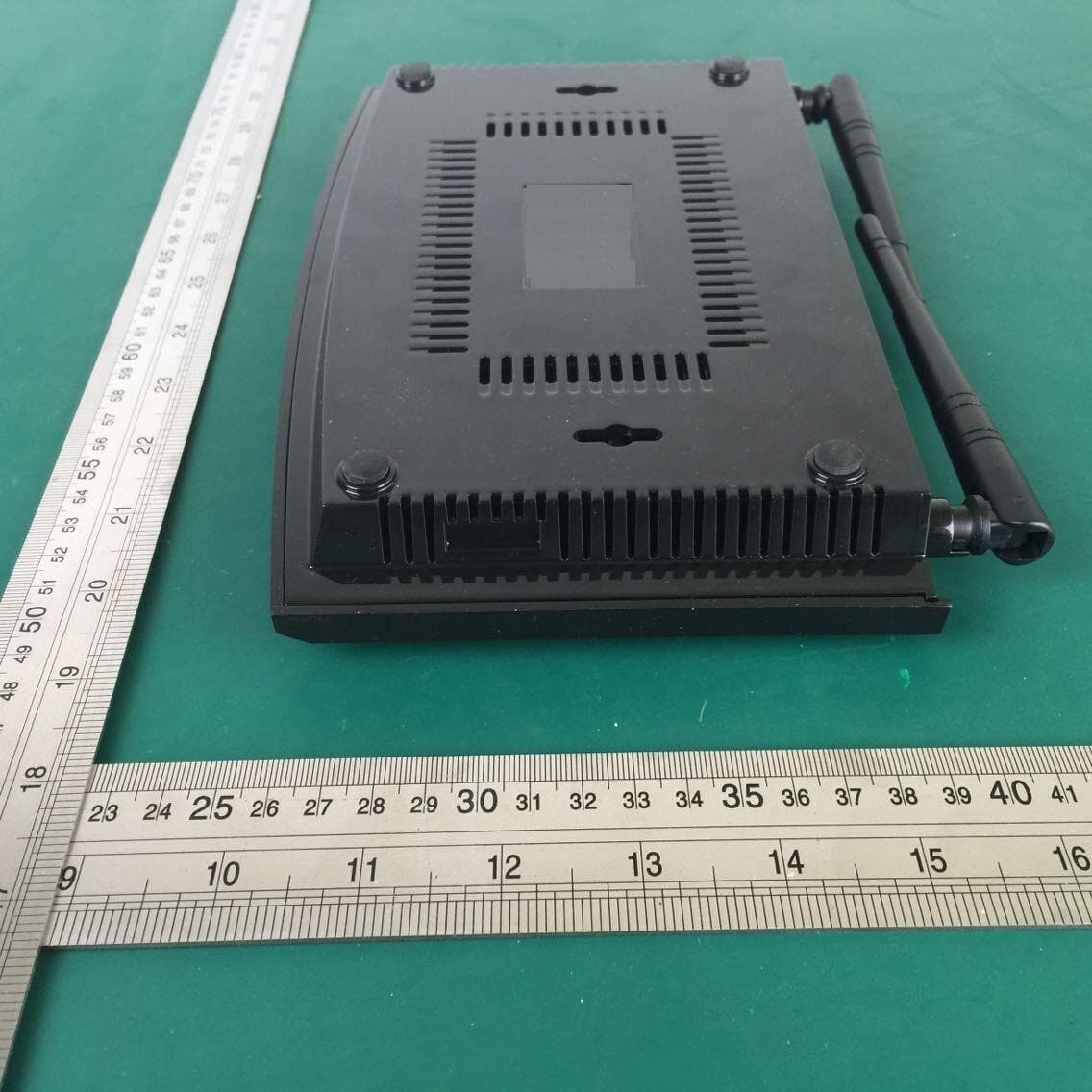
WMXGWZ2100
Apr 15, 2015WiFi/Zigbee Gateway
Equipment Class
DTS - Digital Transmission System