WNY6401404305RF Remote Dimmer
Light Engine Limited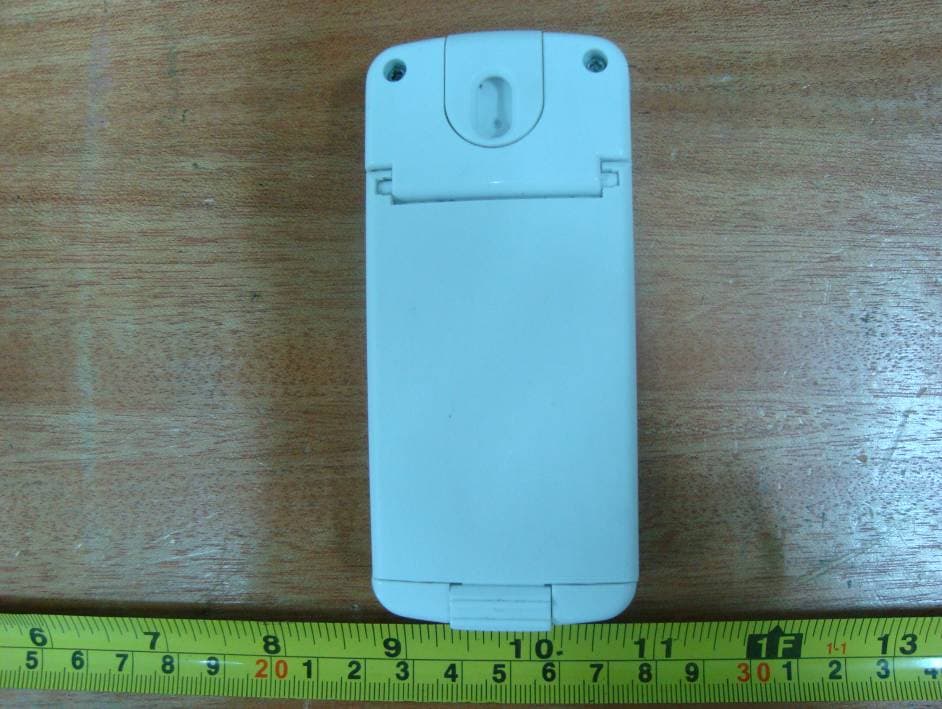
Click to zoom
Application Details
- Equipment Class
- DXX - Part 15 Low Power Communication Device Transmitter
- Date of Grant
- Sep 23, 2011
- Application Purpose
- Original Equipment
- Date of Application
- Sep 23, 2011
- Equipment Note
- RF Remote Dimmer
- Frequency Range
- 2410.00000000 - 2460.00000000
- Company
- Light Engine Limited
- Country
- China
Documents & Files
Document Text
Text extracted from the exhibit documents filed with the FCC. Open a document above to read the original.
Users Manual
Accessories Quick Start Guide Flexi ble Linear Lighting System The versatil e indoor and outdoor water resistant l ighting solution. CabLED™ Accessories Dimension 78.5mm CabLED™ Strip Speci cation Install Inline ON/OFF Dimmer Switch Inline ON/OFF Dimmer Switch Connects to PS-Link Connector. O ers full dimming range, fades the CabLED™ system on and o at last selected dimming level. Connect Inline ON/OFF Dimmer Switch The Inline ON/OFF Dimmer Switch ts between the PS-Link Connector and the power supply. Unplug the power supply from the AC outlet before connecting. Match the icons on the PS-Link Connector with the icons on the Inline Dimmer. Unplu g the power supply from the AC outle t before connecting. Install t he receiver between the power suppl y and the PS-Link Connector by matching the icons on the plugs. Install RF Remote Dimmer Install RF Remote Dimmer The wirele ss Remote Dimmer works only with CabLED™ Receivers. Both the Dimmer and Receiver are rated IP65, comple tely weather resistant but not to be submerged in water. You may use one Dimmer to control up to ten CabLED™ systems, each connected to its own CabLED™ Receiver. The Dimmer MUST be synchroniz ed with each Receiver. Mount Inline ON/OFF Dimmer Switch Position Inline ON/O Dimmer Switch between power suppl y and PS-Link Connector. The Inline Dimmer uses a keyhole mounting system designed to be mounted vertically. 50mm23mm 115.5mm RF Light/Motion Sensor Wireless 2.4 GHz Light/Motion Sensor activates CabLED™ system by sensing motion, light or both. Must be used with at least one RF Receiver and can be synchronized with up to ten RF Receivers. 67mm68mm 102mm 110mm 50mm 50mm27mm 20mm 10.7mm 30mm RF Receiver for RF Remote Dimmer OR RF Light/Motion Sensor 2.4 GHz RF Receiver connects to PS-Link Connector and can be synchronized with either the Remote Dimmer OR Light/Motion Sensor. 39mm CabLED™ Acessories Layout This diagram illustrates possible layouts for the CabLED™ 8000 Series Accessories. Refer to the Component Overvi ew for additional i nformation. AC Outlet Power Supply OR P P P P P S Optional Accessories Optional 1 Optional 2 Inline ON/OFF Dimmer Switch RF Receiver RF Remote Dimmer RF Light/motion Sensor AND OR RF Remote Dimmer Wireless 2.4 GHz Remote Dimmer fades CabLED™ system on/o , o er full dimming range and retains last dimming level. Must be used with at lease one RF Receiver and can be synchronized with up to ten RF Receivers Model Name Model Name RF Distance Model Name Model Name Inline ON/OFF Dimmer Switch RF Light/Motion Sensor RF ReceiverRF Remote Dimmer Input Voltage Standby Current 24V26V3V3V 33uA50uA 15mA20mA 99uW150uW 15mA50mA 4A/25m4A/25m Input Power Input Current 96W/25m96W/25m --------30m30m30m ------------------------ 160 o ------------------------12m IP65IP Rating Operating Temp. StorageTemperature Weight -20 o ~ 50 o 0 o ~ 80 o 85g120g85g85g Detection Angle Detection Distance Power Button: On/O Level 5 (max) (shown) Level 4 Level 3 Level 2 Level 1 (min) Light Bar Indicator: +: Increase light level - : Decrease light level Dimming Bar: ! Maximum length of CabLED™ CANNOT be over 25m. A Screw M4 screw partially into surface, leaving 1/4 inch to hang the Inline Dimmer. B Fi t center of keyhole in back of Inline Dimmer over screw and slide down to mount. Plu g the power suppl y into the AC outlet to synchroniz e it to the Remote Dimmer. ! Disconnect Inline Dimmer from power supply before mounting. P S Connectors PS-Link Connector 4 Way Power Splitter Open the back cover of t he Remote Dimmer and Insert 2 AAA batteries matching the pol arity (+ and -) markings on the batteries with the indicators i n the battery compartment. Install RF Remote Dimmer (Continued) Install Battery in the RF Remote Dimmer Fol low these instructions to mount each RF Receiver to be used with either the Remote Dimmer or t he Light/Motion Sensor. Mount RF Receiver Unlock the receiver case and open it to access the sync switch. Move the power button to AUTO. Use a pin or straightened paper clip to push the sync button. Synchronize One RF Receiver with RF Remote Dimmer Sync Sync On Auto Off OffAutoOn OffAutoOn Push switch to AUTO unlocked position Sync On Auto Off OffAutoOn OffAutoOn Push switch to AUTO unlocked position A Screw two M4 screw partially into surface, leaving 1/4 inch to mount the receiver. Screw two M4 screw partially into surface, leaving 1/4 inch to mount the receiver. A Fit center of keyhole s i n back of r eceiver over each screw and slide to one side to secure. Fit center of keyhole s i n back of r eceiver over each screw and slide to one side to secure. A Unlock the receiver case and open it to access the sync switch. Move the power button to AUTO. Use a pin or straightened paper clip to push the sync button. Synchronize One RF Receiver with RF Light/Motion Sensor A With the battery compartment on the front of t he Light/Motion Sensor, access the control s. Turn the power ON. Use a pin or straightened paper clip to push the sync button. B Open the battery compartment on the back of t he Remote Dimmer to access the sync switch. Use a pin or straightened paper clip to push the sync button. When the CabLED™ strip start blinking, the Remote Dimmer is successfully synchroniz ed with the Receiver. Blue LED blink if not success synchronized in 30 sec. Press Sync button 6 sec in paring to reset. B Sync blue LED light up when low battery Sync Power Button: On/O Blue LED: Lights when in use Dimming Bar: +: Increase light level - : Decrease light level Unplu g the power supply from the AC outle t before connecting. Install t he receiver between the power suppl y and the PS-Link Connector by matching the icons on the plugs. Install RF Light/Motion Sensor Install RF Remote Dimmer Mount Horizontally Open the front battery compartment cover using a at screw driver. Insert 2 AAA batteries matching the polarity (+ and -) markings on the batteries with the indicators in the battery compartment. Install Batteries in the RF Ligh…
Text truncated - open the document above for the full version.
External Photos
EXHIBIT B - EUT EXTERNAL PHOTOGRAPHS EUT – Top View EUT – Bottom View
ID Label/Location Info
EXHIBIT A - FCC ID LABELING AND LOCATION FCC ID Label FCC ID Label Location The label shown shall be permanently affixed at a conspicuous location on the device and be readily visible to the user at the time purchase (Labeling requirements per 2.925)
Internal Photos
EXHIBIT C - EUT INTERNAL PHOTOGRAPHS EUT – Cover off View EUT – Main Board Top View Antenna EUT – Main Board Bottom View
Test Report
Note: This test report is prepared for the customer shown above and for the equipment described herein. It may not be duplicated or used in part without prior written consent from Bay Area Compliance Laboratories Corp. This report must not be used by the customer to claim product certification, approval, or endorsement by NVLAP*, or any agency of the Federal Government. * This report contains data that are not covered by the NVLAP accreditation and are marked with an asterisk “★” (Rev.2) FCC PART 15.249 TEST REPORT For Light Engine Limited 6/F, Photonics Centre, 2 Science Park East Avenue, Hong Kong Science Park, Shatin, Hong Kong FCC ID: WNY6401404305 Report Type: Original Report Product Type: P169 Remote Test Engineer: Leon Chen Report Number: RSZ11031454-00 Report Date: 2011-09-19 Reviewed By: Alvin Huang EMC Engineer Test Laboratory: Bay Area Compliance Laboratories Corp. (Shenzhen) 6/F, the 3rd Phase of WanLi Industrial Building, ShiHua Road, FuTian Free Trade Zone Shenzhen, Guangdong, China Tel: +86-755-33320018 Fax: +86-755-33320008 www.baclcorp.com.cn Bay Area Compliance Laboratories Corp. (Shenzhen) Report No.: RSZ11031454-00 FCC Part 15.249 Page 2 of 15 TABLE OF CONTENTS GENERAL INFORMATION.......................................................................................................................................3 PRODUCT DESCRIPTION FOR EQUIPMENT UNDER TEST (EUT) .....................................................................................3 OBJECTIVE...................................................................................................................................................................3 RELATED SUBMITTAL(S)/GRANT(S).............................................................................................................................3 TEST METHODOLOGY..................................................................................................................................................3 TEST FACILITY.............................................................................................................................................................3 SYSTEM TEST CONFIGURATION ..........................................................................................................................5 JUSTIFICATION.............................................................................................................................................................5 EQUIPMENT MODIFICATIONS.......................................................................................................................................5 EXTERNAL I/O CABLE..................................................................................................................................................5 CONFIGURATION OF TEST SETUP.................................................................................................................................5 BLOCK DIAGRAM OF TEST SETUP................................................................................................................................5 SUMMARY OF TEST RESULTS ...............................................................................................................................6 FCC §15.203 - ANTENNA REQUIREMENT.............................................................................................................7 APPLICABLE STANDARD..............................................................................................................................................7 ANTENNA CONNECTOR CONSTRUCTION......................................................................................................................7 FCC §15.205, §15.209 & §15.249 - RADIATED EMISSIONS ..................................................................................8 APPLICABLE STANDARD..............................................................................................................................................8 MEASUREMENT UNCERTAINTY....................................................................................................................................8 TEST EQUIPMENT SETUP..............................................................................................................................................8 EUT SETUP..................................................................................................................................................................9 TEST EQUIPMENT LIST AND DETAILS...........................................................................................................................9 TEST PROCEDURE......................................................................................................................................................10 CORRECTED AMPLITUDE & MARGIN CALCULATION.................................................................................................10 TEST RESULTS SUMMARY..........................................................................................................................................10 TEST DATA................................................................................................................................................................10 FCC §15.215(C) – 20 DB EMISSION BANDWIDTH..............................................................................................14 APPLICABLE STANDARD............................................................................................................................................14 TEST EQUIPMENT LIST AND DETAILS.........................................................................................................................14 TEST PROCEDURE......................................................................................................................................................14 TEST DATA...............................................…
Text truncated - open the document above for the full version.
Test Setup Photos
EXHIBIT D - TEST SETUP PHOTOGRAPHS Below 1 GHz: Spurious Radiated Emissions - Front View Below 1 GHz: Spurious Radiated Emissions - Rear View Above 1 GHz: Spurious Radiated Emissions - Front View Above 1 GHz: Spurious Radiated Emissions - Rear View
Contact Information
Applicant
Donald Mok
Test Firm
Bay Area Compliance Laboratory Corp. (Shenzhen)John Chan
Technical Specifications
| # | Rule Parts | Frequency Range | Power Output |
|---|---|---|---|
| 1 | 15C | 2.41 GHz - 2.46 GHz | - |
Other Applications from Light Engine Limited
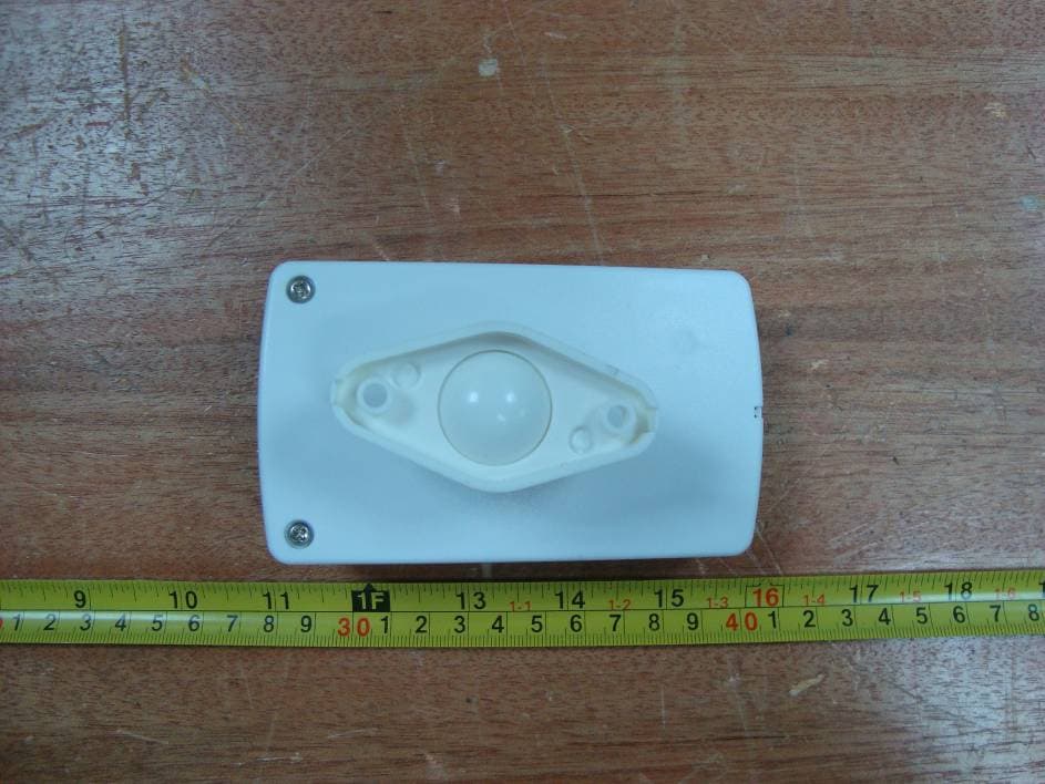
WNY6401404205
Sep 23, 2011RF Light/Motion Sensor
Equipment Class
DXX - Part 15 Low Power Communication Device Transmitter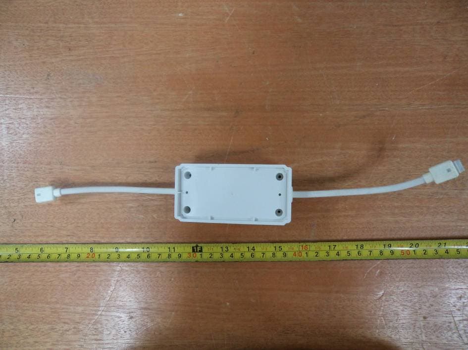
WNY6401404405
Sep 23, 2011Inline ON/OFF Dimmer Switch
Equipment Class
DXX - Part 15 Low Power Communication Device Transmitter