WQ5PDI-TR100WIRELESS TABLE RADIO
PDI Communication System, Inc.
Click to zoom
Application Details
- Equipment Class
- DSS - Part 15 Spread Spectrum Transmitter
- Date of Grant
- Aug 28, 2011
- Application Purpose
- Original Equipment
- Date of Application
- Aug 27, 2011
- Equipment Note
- WIRELESS TABLE RADIO
- Frequency Range
- 2402.00000000 - 2480.00000000
- Country
- United States
Documents & Files
Document Text
Text extracted from the exhibit documents filed with the FCC. Open a document above to read the original.
Users Manual
PDI-TR100 TABLE RADIO The lightning flash with arrow-head symbol within an equilateral triangle is intended to alert the user to the presence of uninsulated"dangerousvoltage"within the unit’s enclosure that may be of sufficient magnitude to constitute a risk of electric shock. The exclamation point within an equilateral triangle is intended to alert the user to the presence of important operating and maintenance (servicing) instructions in the literature accompanying the unit. CAUTION TO REDUCE THE RISK OF ELECTRIC SHOCK, DO NOT REMOVE COVER OR BACK. THERE ARE NO USER- SERVICEABLE PARTS INSIDE. REFER SERVICING TO QUALIFIED SERVICE PERSONNEL. TO REDUCE THE RISK OF FIRE OR ELECTRIC SHOCK, DO NOT EXPOSE THIS UNIT TO RAIN OR MOISTURE. FCC INFORMATION This equipment has been tested and found to comply with the limits for Class B digital devices, pursuant to part 15 of FCC Rules. These limits are designed to provide reasonable protection against harmful interference installation. This equipment generates, uses and can radiate radio frequency energy and, if not installed and used in accordance with the TABLE RADIO PDI-TR100 CAUTION: TO REDUCE THE RISK OF ELECTRIC SHOCK.DO NOT REMOVE COVER (OR BACK) NO USER SERVICEABLE PARTS INSIDE.REFER SERVICING TO QUALIFIED SERVICE PERSONNEL. CAUTION institutions, may cause harmful interference to radio communications. However, there is no guarantee that interference will not occur in a particular installation. If this equipment does cause harmful interference to radio or television reception, which can be determined by turning the equipment off and on, the user is encouraged to try to correct the interference by one or more of the following measures: Reorient or relocate the receiving antenna. Increase the separation between the equipment and receiver. Connect the equipment into an outlet on a circuit different from that to which the receiver is connected. Consult the dealer or an experienced radio/TV technician for help. This equipment complies with Part 15 of the FCC Rules. Operation is subject to the following two conditions: Statement: Changes or modifications not expressly approved by the party responsible for compliance could void the user’s authority to operate the equipment. TABLE RADIO PDI-TR100 CONTENTS Read this manual carefully to get the best performance from this unit. Package contents Mount clock battery Specifications Menu Front panel Rear panel Operation (1)AM/FM OPERATION (2) TV WIRELESS CONNECTION (3)MUTE FUNCTION (4)BASS/TREBLE FUNCTION (5)ALARM CLOCK (6)DIMMER ADJUSTMENT 安全警告 目录 TABLE RADIO PDI-TR100 1 2 5 2 5 2 5 3 6 4 6 5 6 2 1 1.PDI-TR100 unit 1PC. 2.15V AC adaptor 1PC. 3.FM antenna 1PC. 4.AM antenna 1PC. 5.2XAAA batteries 2PC. 6.Owners manual 1PC. 1 3 4 5 Package contents 6 T A B L E R A D I O P D I - T R 1 0 0 TABLE RADIO PDI-TR100 2 Menu 2 x AAA TVLINK 12:00AM 15M01 ABC D E F A G Specifications ·FM/AM tuner. FM Frequency range: 87.5- 108MHz. AM Frequency range: 530- 1700KHz. Wireless audio output. Driver: 3” full range. Back-lit display. TV channel selection. INPUT:15V 1.6A DC, external power supply. OUTPUT:Battery back-up for clockAlarm function. Working temperature: -5C to +40C. Size: H120xD140xW180mm. · · · · · · · · · · (A)Indicates Function on. (B)Indicates ALARM on. (C)Blinks when link to TV. (D)Indicates Volume. (E)Blinks when poor or no battery. (F)Display memory-station. (G)Display frequency, clock. BASS -3 > +3 TREBLE -3 > +3 ALARM ALM OFF HOUR ALM On Min TABLE RADIO PDI-TR100 Mount clock battery 3 (1)VOLUME KNOB Adjust the volume knob to desired listening level. Push for mute and push again or tuning the knob to turn on the volume. FUNCTION KNOB STANDBY (Display the clock) TV MODE FM MODE AM MODE (3)TUNING KNOB Adjust the “TUNING” to choose the radio station . Adjust the “TUNING” to choose the TV station. Longpush “TUNING” for 3 seconds to enter the “MENU”. (4)LCD DISPLAY (5)SPEAKER · · (2) · · · · · · · Front panel TABLE RADIO PDI-TR100 1 2 3 4 5 SCAN CLOCK SET PAIR DC15V-1.6A ANTENNA FM ANTENNA AM C L O C K B A T T E R Y 6 7 8910 1112 13 FM EXTERNALANTENNAJACK Connect the enclosed external FM antenna if reception is poor ,You can also connect a communal aerial. (7)AM EXTERNALANTENNAJACK Connect the enclosed external AM antenna if reception is poor ,You can also connect a communal aerial. (8)PAIR TO TV BUTTON (9)CLOCK SET BUTTON (10)AUTO SCAN BUTTON (11)DC ADAPTOR JACK (12)LOCK FOR UNIT (13)BATTERY LID (6) · · 4 Rear panel TABLE RADIO PDI-TR100 5 (1) (2) (3) AM/FM OPERATION Make sure the DC power adaptor is connecting to the unit . ——Choose the function to AM/FM mode, Adjust the “TUNING”(3)to choose the desired radio station . ——Fine tune by short adjust AM -/+10KHz, FM -/+100KHz. ——Choose the function to AM/FM mode,push “SCAN”(10)on the rear panel. After scan,”M01-M20” will display on the right corner of the LCD. Adjust the “TUNING”(3)to choose the radio station. If you want cancel the scan, push the “SCAN”(10)again. ——”M01-M20” it means the unit can restore most 20pcs stations. TV WIRELESS CONNECTION ——Make sure the DC adaptor is connecting to unit.Adjust the function knob to “STANDBY”,Long push “VOLUME”(1) until “TR100-01”display on the LCD. ——Adjust the function knob to “TV”(2),Long push the “PAIR”(8) 5 seconds.the “PAIR” will display and blink on the LCD. In the mean time ,you can open the TV wirless connect mode to search the unit .”TR100-01”will display on the LCD. Then input the code “0000”,Once the pair is successful ,”LINK”will display on the LCD of TV and TR100. Then adjust the “TUNING”(3) to choose the TV channel. ——The limited time of pairing is one minute ,If the pair is unsuccessful. You can reset the “PAIR”(8) 5 seconds again. Once the pairing is successful, You don’t to pair the TV any more in the future . Mute function Push the “VOLUME”(1) for mute, Push again to cancel the mute. (4)BASS/TREBLE FUNCTION In TV/FM/AM mode , ,long push the “TUNING”(3) for 3 seconds TABLE RADIO PDI-TR100 OPERATION . “MENU”…
Text truncated - open the document above for the full version.
External Photos
1 Photographs - EUT Constructional Details(Test Model No.: PDI-TR100)
Internal Photos
7 Photographs - EUT Constructional Details (Test Model No.: PDI-TR100)
RF Exposure Info
SGS-CSTC Standards Technical Services Co., Ltd. No. 1 Workshop, M-10, Middle section, Science & Technology Park, Shenzhen, Guangdong, China 518057 Telephone: +86 (0) 755 2601 2053 Fax: +86 (0) 755 2671 0594 Email: [email protected] Report No.: SZEM110600137102 Page: 1 of 3 Authorized Signature: Jack Zhang EMC Laboratory Manager The manufacturer should ensure that all products in series production are in conformity with the product sample detailed in this report. If the product in this report is used in any configuration other than that detailed in the report, the manufacturer must ensure the new system complies with all relevant standards. Any mention of SGS International Electrical Approvals or testing done by SGS International Electrical Approvals in connection with, distribution or use of the product described in this report must be approved by SGS International Electrical Approvals in writing. The report must not be used by the client to claim product certification, approval, or endorsement by NVLAP, NIST, or any agency of the federal government. All test results in this report can be traceable to National or International Standards. “This document is issued by the Company subject to its General Conditions of Service printed overleaf, available on request or accessible at www.sgs.com/terms_and_conditions.htm and, for electronic format documents, subject to Terms and Conditions for Electronic Documents at www.sgs.com/terms_e-document.htm . Attention is drawn to the limitation of liability, indemnification and jurisdiction issues defined therein. Any holder of this document is advised that information contained hereon reflects the Company’s findings at the time of its intervention only and within the limits of Client’s instructions, if any. The Company’s sole responsibility is to its Client and this document does not exonerate parties to a transaction from exercising all their rights and obligations under the transaction documents. This document cannot be reproduced except in full, without prior written approval of the Company. Any unauthorized alteration, forgery or falsification of the content or appearance of this document is unlawful and offenders may be prosecuted to the fullest extent of the law. Unless otherwise stated the results shown in this test report refer only to the sample(s) tested and such sample(s) are retained for 90 days only.” 1 RF Exposure Evaluation declaration Application No.: SZEM1106001371RF Applicant: PDi Communication Systems, Inc. Address of Applicant: 40 Greenwood Lane, Springboro, OH 45066 USA Manufacturer: kaito enterprises corp Address of Manufacturer: 11/F, Electronics Science & Technology Building 2070 A Shennan Central Road, Shenzhen, China Factory: HUITAI (GUANGDONG) DIGITAL SCIENCE & TECHNOLOGY CO., LTD. Address of Factory: No.6th, Songbai Road, South Area, Huizhou Digital Industrial Park, Huiao Highway, Huizhou, Guangdong P.R.C FCC ID: WQ5PDI-TR100 Fundamental Carrier Frequency: 2402MHz~2480MHz Equipment Under Test (EUT): Name: WIRELESS TABLE RADIO Model: PDI-TR100 Date of Receipt: 2011-06-15 Date of Test: 2011-06-15 to 2011-08-15 Date of Issue: 2011-08-24 Test Result : PASS* * In the configuration tested, the EUT complied with the standards specified above. SGS-CSTC Standards Technical Services Co., Ltd. Report No.: SZEM110600137102 Page: 2 of 3 “This document is issued by the Company subject to its General Conditions of Service printed overleaf, available on request or accessible at www.sgs.com/terms_and_conditions.htm and, for electronic format documents, subject to Terms and Conditions for Electronic Documents at www.sgs.com/terms_e-document.htm . Attention is drawn to the limitation of liability, indemnification and jurisdiction issues defined therein. Any holder of this document is advised that information contained hereon reflects the Company’s findings at the time of its intervention only and within the limits of Client’s instructions, if any. The Company’s sole responsibility is to its Client and this document does not exonerate parties to a transaction from exercising all their rights and obligations under the transaction documents. This document cannot be reproduced except in full, without prior written approval of the Company. Any unauthorized alteration, forgery or falsification of the content or appearance of this document is unlawful and offenders may be prosecuted to the fullest extent of the law. Unless otherwise stated the results shown in this test report refer only to the sample(s) tested and such sample(s) are retained for 90 days only.” 2 RF Exposure Evaluation 2.1 Limits According to FCC 1.1310: The criteria listed in the following table shall be used to evaluate the environment impact of human exposure to radio frequency (RF) radiation as specified in1.1307(b) LIMITS FOR MAXIMUM PERMISSIBLE EXPOSURE (MPE) Frequency Range (MHz) Electric Field Strength (V/m) Magnetic Field Strength (A/m) Power Density (mW/cm2) Average Time (Minutes) (A) Limits for Occupational/ Control Exposures 300-1500 -- -- F/300 6 1500-100,000 -- -- 5 6 300-1500 -- -- F/1500 6 1500-100,000 -- -- 1 300 F= Frequency in MHz Friis Formula Friis transmission formula: Pd = (Pout*G)/(4* Pi * R 2 ) Where Pd = power density in mW/cm 2 Pout = output power to antenna in mW G = gain of antenna in linear scale Pi = 3.1416 R = distance between observation point and center of the radiator in cm Pd id the limit of MPE, 1 mW/cm2 . If we know the maximum gain of the antenna and the total power input to the antenna, through the calculation, we will know the distance r where the MPE limit is reached. SGS-CSTC Standards Technical Services Co., Ltd. Report No.: SZEM110600137102 Page: 3 of 3 “This document is issued by the Company subject to its General Conditions of Service printed overleaf, available on request or accessible at www.sgs.com/terms_and_conditions.htm and, for electronic format documents, subject to Terms and Conditions for Electronic Documents at w…
Text truncated - open the document above for the full version.
Test Report
SGS-CSTC Standards Technical Services Ltd. No. 1 Workshop, M-10, Middle section, Science & Technology Park, Shenzhen, Guangdong, China 518057 Telephone: +86 (0) 755 2601 2053 Fax: +86 (0) 755 2671 0594 Email: [email protected] Report No.: SZEM110600137101 Page: 1 of 69 Authorized Signature: Jack Zhang EMC Laboratory Manager The manufacturer should ensure that all products in series production are in conformity with the product sample detailed in this report. If the product in this report is used in any configuration other than that detailed in the report, the manufacturer must ensure the new system complies with all relevant standards. Any mention of SGS International Electrical Approvals or testing done by SGS International Electrical Approvals in connection with, distribution or use of the product described in this report must be approved by SGS International Electrical Approvals in writing. The report must not be used by the client to claim product certification, approval, or endorsement by NVLAP, NIST, or any agency of the federal government. All test results in this report can be traceable to National or International Standards. “This document is issued by the Company subject to its General Conditions of Service printed overleaf, available on request or accessible at www.sgs.com/terms_and_conditions.htm and, for electronic format documents, subject to Terms and Conditions for Electronic Documents at www.sgs.com/terms_e-document.htm . Attention is drawn to the limitation of liability, indemnification and jurisdiction issues defined therein. Any holder of this document is advised that information contained hereon reflects the Company’s findings at the time of its intervention only and within the limits of Client’s instructions, if any. The Company’s sole responsibility is to its Client and this document does not exonerate parties to a transaction from exercising all their rights and obligations under the transaction documents. This document cannot be reproduced except in full, without prior written approval of the Company. Any unauthorized alteration, forgery or falsification of the content or appearance of this document is unlawful and offenders may be prosecuted to the fullest extent of the law. Unless otherwise stated the results shown in this test report refer only to the sample(s) tested and such sample(s) are retained for 90 days only.” 1 Cover Page FCC REPORT Application No: SZEM1106001371RF Applicant: PDi Communication Systems, Inc. Product Name: WIRELESS TABLE RADIO Operation Frequency: 2.402GHz to 2.480GHz FCC ID: WQ5PDI-TR100 Standards: FCC CFR Title 47 Part 15 Subpart C Date of Receipt: 2011-06-15 Date of Test: 2011-06-15 to 2011-08-15 Date of Issue: 2011-08-24 Test Result : PASS * * In the configuration tested, the EUT complied with the standards specified above. SGS-CSTC Standards Technical Services Ltd. Report No.: SZEM110600137101 Page: 2 of 69 “This document is issued by the Company subject to its General Conditions of Service printed overleaf, available on request or accessible at www.sgs.com/terms_and_conditions.htm and, for electronic format documents, subject to Terms and Conditions for Electronic Documents at www.sgs.com/terms_e-document.htm . Attention is drawn to the limitation of liability, indemnification and jurisdiction issues defined therein. Any holder of this document is advised that information contained hereon reflects the Company’s findings at the time of its intervention only and within the limits of Client’s instructions, if any. The Company’s sole responsibility is to its Client and this document does not exonerate parties to a transaction from exercising all their rights and obligations under the transaction documents. This document cannot be reproduced except in full, without prior written approval of the Company. Any unauthorized alteration, forgery or falsification of the content or appearance of this document is unlawful and offenders may be prosecuted to the fullest extent of the law. Unless otherwise stated the results shown in this test report refer only to the sample(s) tested and such sample(s) are retained for 90 days only.” 2 Contents Page 1 COVER PAGE.........................................................................................................................................................1 2 CONTENTS.............................................................................................................................................................. 2 3 TEST SUMMARY.................................................................................................................................................... 3 4 GENERAL INFORMATION................................................................................................................................... 4 4.1 CLIENT INFORMATION.......................................................................................................................................... 4 4.2 GENERAL DESCRIPTION OF E.U.T. ....................................................................................................................... 4 4.3 E.U.T OPERATION MODE...................................................................................................................................... 6 4.4 DESCRIPTION OF SUPPORT UNITS......................................................................................................................... 6 4.5 TEST FACILITY..................................................................................................................................................... 6 4.6 TEST LOCATION................................................................................................................................................... 6 4.7 OTHER INFORMATION REQUESTED BY THE CUSTOMER........................................................................................ 6 4.8 TEST INSTRUMENTS LIST.........................…
Text truncated - open the document above for the full version.
Test Setup Photos
1 Photographs - Test Setup Photo (Test Model No.: PDI-TR100) Conducted Emission Test Setup Radiated Emission Test Setup
Contact Information
Applicant
Norman Mau(Manager)
Technical Contact
SGS-CSTC Standards Technical ServicesLtdLuo Sheek
[email protected]0755-2654 4119
No.1 Workshop, M-10, Middle Section, · Shenzhen · China
Test Firm
SGS-CSTC Standards Technical Services Co.,Ltd.June Zhang
Technical Specifications
| # | Rule Parts | Frequency Range | Power Output |
|---|---|---|---|
| 1 | 15C | 2.40 GHz - 2.48 GHz | 400.00 µW |
Other Applications from PDI Communication System, Inc.
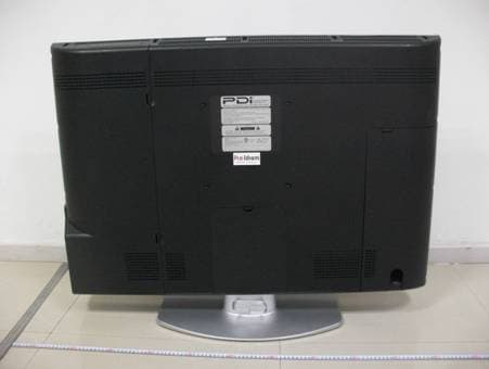
WQ5P40LCDEN
Jan 08, 2013LCD TV
Equipment Class
DXX - Part 15 Low Power Communication Device Transmitter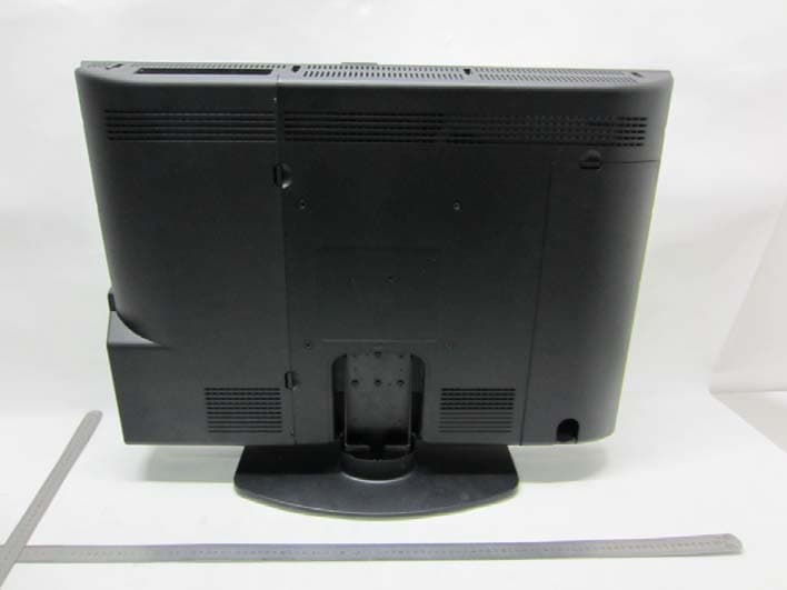
WQ5P32LCDEN
Jan 07, 2013LCD TV
Equipment Class
DXX - Part 15 Low Power Communication Device Transmitter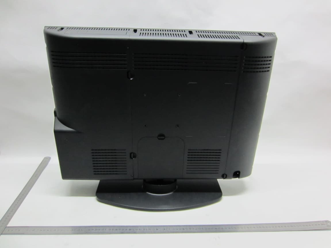
WQ5P26LCDEN
Jan 06, 2013LCD TV
Equipment Class
JBP - Part 15 Class B Computing Device Peripheral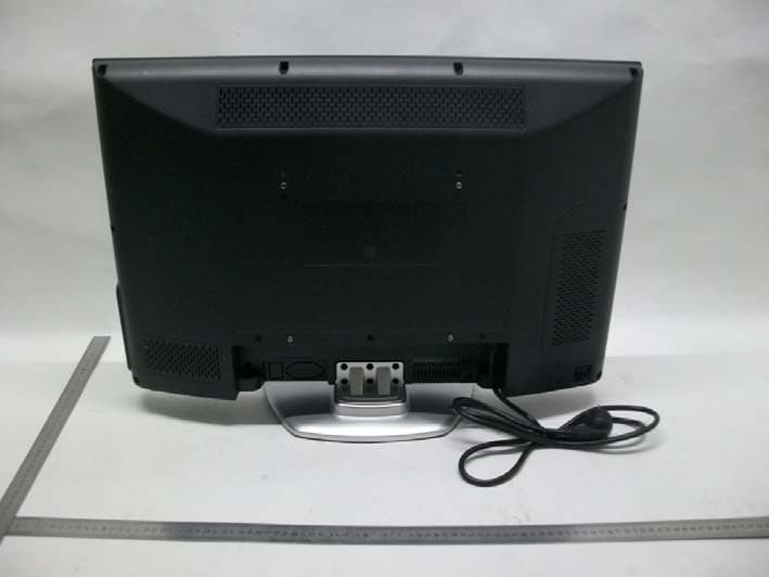
WQ5CV2600N
Dec 20, 2012LCD TV
Equipment Class
JBP - Part 15 Class B Computing Device Peripheral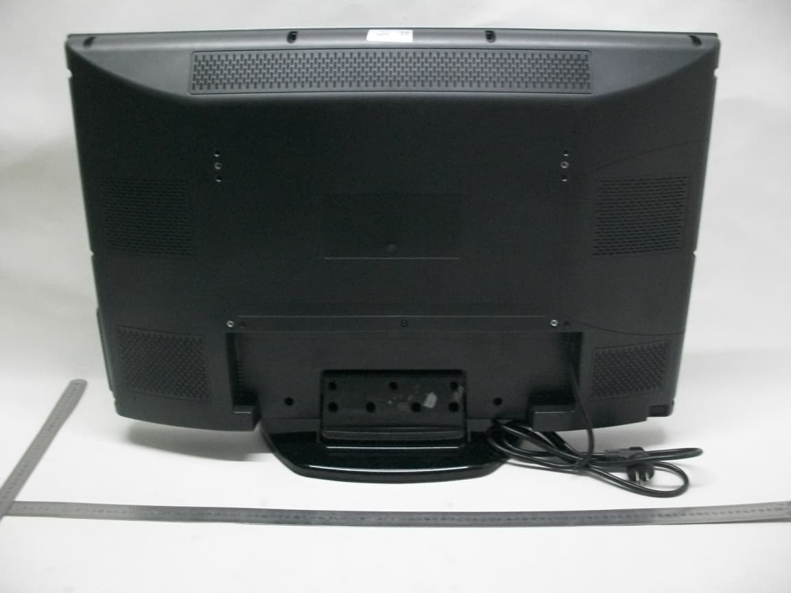
WQ5CV3200N
Dec 20, 2012LCD TV
Equipment Class
JBP - Part 15 Class B Computing Device Peripheral