WQ8-2012J2534J2534 ECU Programming Device
Autel Intelligent Technology Corp., Ltd.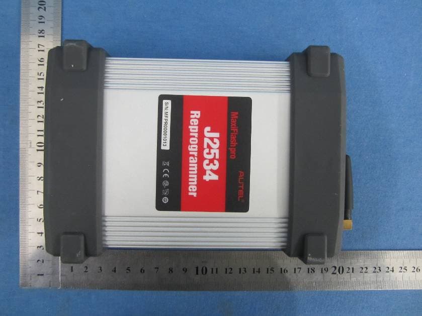
Click to zoom
Application Details
- Equipment Class
- DTS - Digital Transmission System
- Date of Grant
- Jan 15, 2013
- Application Purpose
- Original Equipment
- Date of Application
- Jan 15, 2013
- Equipment Note
- J2534 ECU Programming Device
- Frequency Range
- 2412.00000000 - 2462.00000000
- Country
- China
Documents & Files
Document Text
Text extracted from the exhibit documents filed with the FCC. Open a document above to read the original.
Users Manual
Table of Contents 1. INTRODUCTION ............................................................................................ 1 1.1 BACKGROUND ............................................................................................... 1 1.2 J2534 - A SOLUTION ARRIVES ...................................................................... 1 1.3 PASS-THRU VEHICLE INTERFACE ................................................................. 2 2. GETTING TO KNOW MAXIFLASH PRO .................................................. 3 2.1 FRONT PANEL ............................................................................................... 3 2.2 REAR PANEL ................................................................................................. 5 2.3 POWER UP ..................................................................................................... 7 2.4 SPECIFICATIONS ............................................................................................ 7 2.5 ACCESSORIES INCLUDED............................................................................... 9 2.6 PRODUCT TROUBLESHOOTING.................................................................... 10 3. DRIVER SETUP & NETWORK CONFIGURING .................................... 11 3.1 DRIVER SETUP ............................................................................................ 11 3.2 NETWORK CONFIGURATION ....................................................................... 12 4. REPROGRAMMING WITH J2534 DEVICE ............................................. 19 5. SOFTWARE UPDATE .................................................................................. 21 6. WARRANTY AND SERVICE ...................................................................... 24 6.1 LIMITED ONE YEAR WARRANTY ................................................................ 24 6.2 SERVICE PROCEDURES ................................................................................ 24 1 1. Introduction 1.1 Background The days of diagnosing and repairing automobiles without a laptop beside you are quickly fading. Newer vehicles include a large number of onboard computers that are each dedicated to performing specific tasks. Common onboard computers in newer vehicle include the Engine Control Module (ECM), Transmission Control Module (TCM), Fuel Injection Control Module (FICM), Anti-lock Brake System (ABS), Body Control Module (BCM) and numerous other control modules to manage every electronic system from power door locks to crash data. Each onboard computer is programmed at the factory with software enabling it to perform certain tasks. Inside the ECM is software containing hundreds or even thousands of parameters to control spark, fuel, idle, cruising, emissions, economy, drivability, and performance. Likewise, a TCM will have software to control how the transmission and torque converter function. Sometimes, after the vehicle is shipped from the automaker, updates are released to improve emissions, fuel economy, drivability, performance, or specific bugs in the original software that have caused warranty issues. Updating this software can be a proactive fix because often it will resolve problems that a customer hasn’t reported or noticed yet. The practice of updating software in these modules is more commonly known as flash reprogramming. At new car dealerships, flash reprogramming is relatively straight forward because service technicians are connected to the automaker and have the expensive, specialized dealer service tools dedicated to reprogramming. The independent repair shops have faced a more difficult challenge because most shops typically service more than one make of vehicles. This increases the complexity, cost and training required to operate dozens of different factory service tools. 1.2 J2534 - A Solution Arrives In 2000, the Environmental Protection Agency (EPA) had been watching this issue and decided to take action. The EPA requested a standard be developed within the SAE that led to J2534, a mandated 2 specification to which automakers who sell vehicles in the United States must conform. The original J2534 specification was later updated to J2534-1 in order to support all automakers. The EPA mandate requires automakers to support aftermarket repair shops with J2534-1 flash reprogramming for any emissions related computer modules on a vehicle that can be reprogrammed by a new car dealership. This mandate took effect for all 2004 and newer vehicles. SAE J2534 is a standard devised of two independent parts: subscription software and a J2534 compliant Pass Thru vehicle interface. The subscription software comes directly from the automaker, runs on your shop PC or laptop, and can either be web-based or CD-based. The subscription fees are charged differently for each automaker. 1.3 Pass-Thru Vehicle Interface The second part of the system is a SAE J2534 compliant Pass-Thru vehicle interface. This device acts as a gateway between the vehicle’s onboard computers and the technician’s personal computer. It translates messages from the PC into the protocols used by the automobile and vice versa. Performing J2534 reprogramming requires computer knowledge and experience. The technician will need to operate a laptop or desktop, the Pass-Thru device, and the reprogramming software. Operation will also require a good high-speed connection to the Internet such as DSL, Cable, or T1. 3 2. Getting to Know MaxiFlash Pro Thank you for choosing the MaxiFlash ® Pro Reprogramming Device! This multi-protocol Pass-Thru vehicle interface is a fully compliant SAE J2534-1 & SAE J2534-2 (March 2006) device, specially designed to provide users with convenient PC communication and ECU reprogramming capabilities on any modern vehicle diagnostic bus, and offer the most significant features desired by OEM customers: reliability, fast performance and flexibility. 2.1 Front Panel The MaxiFlash ® Pro Pass-Thru device supports three ways of PC con…
Text truncated - open the document above for the full version.
Cover Letter(s)
Date: 2012-12-22 To: Federal Communications Commission 7435 Oakland Mills Road Columbia, MD FCC ID: WQ8-2012J2534 To Whom It May Concern: We, Shenzhen Autel Intelligent Tech. Co., Ltd., are applying FCC DOC for product TPMS diagnostic and service tool which model no. is MaxiFlash Pro. the FCC DOC is doing at proper FCC authorized and recognized lab, and FCC DOC will be issued soon. If you have any question or concerns, pls. contact us. Sincerely, Client’s signature Client’s name / title Frank Li / Manager Contact information / address Tel: 0755-86329573 Address: Rm. 2205, Overseas Chinese Scholars Venture Bldg. Hi-tech Industrial Park Shenzhen China
ID Label/Location Info
Size: 6mm*3.2mm FCC ID: WQ8-2012J2534 DC 12V 2A
ID Label/Location Info
Label location
RF Exposure Info
RF Exposure Evaluation Limits The criteria listed in the following table shall be used to evaluate the environment impact of human exposure to radio frequency (RF) radiation as specified in 1.1307(b) Limits for Maximum Permissible Exposure (MPE) Frequency range (MHz) Electric field strength (V/m) Magnetic field strength (A/m) Power density (mW/cm 2 ) Averaging time (minutes) (A) Limits for Occupational/Controlled Exposures 0.3–3.0 614 1.63 *(100) 6 3.0–30 1842/f 4.89/f *(900/f 2 ) 6 30–300 61.4 0.163 1.0 6 300–1500 f/300 6 1500–100,000 5 6 (B) Limits for General Population/Uncontrolled Exposure 0.3–1.34 614 1.63 *(100) 30 1.34–30 824/f 2.19/f *(180/f 2 ) 30 30–300 27.5 0.073 0.2 30 300–1500 f/1500 30 1500–100,000 1.0 30 f = frequency in MHz Friis transmission formula: Pd = (Pout*G)/(4*pi*r 2 ) Where Pd = power density in mW/cm 2 , Pout = output power to antenna in mW; G = gain of antenna in linear scale, Pi = 3.1416; R = distance between observation point and center of the radiator in cm Pd id the limit of MPE, 1 mW/cm 2 . If we know the maximum gain of the antenna and the total power input to the antenna, through the calculation, we will know the distance r where the MPE limit is reached. Test Procedure Software provided by client enabled the EUT to transmit and receive data at lowest, middle and highest channel individually. Test Result of RF Exposure Evaluation 802.11g mode Channel Output power to antenna (mW) Power Density at R=20cm (mW/cm 2 ) Limit (mW/cm 2 ) Result Lowest (2412MHz) 36.98 0.01308 1.0 PASS Middle (2437MHz) 36.64 0.01296 1.0 PASS Highest (2462MHz) 38.64 0.01367 1.0 PASS 802.11n(H20) mode Channel Output power to antenna (mW) Power Density at R=20cm (mW/cm 2 ) Limit (mW/cm 2 ) Result Lowest (2412MHz) 19.82 0.00701 1.0 PASS Middle (2437MHz) 17.50 0.00619 1.0 PASS Highest (2462MHz) 18.75 0.00663 1.0 PASS Remark: antenna gain=2.5dBi
Test Report
Global United Technology Services Co., Ltd. Report No.: GTSE12120146301 Authorized Signature: Robinson Lo Laboratory Manager This report details the results of the testing carried out on one sample. The results contained in this test report do not relate to other samples of the same product and does not permit the use of the GTS product certification mark. The manufacturer should ensure that all products in series production are in conformity with the product sample detailed in this report. This report may only be reproduced and distributed in full. If the product in this report is used in any configuration other than that detailed in the report, the manufacturer must ensure the new system complies with all relevant standards. Any mention of GTS International Electrical Approvals or testing done by GTS International Electrical Approvals in connection with, distribution or use of the product described in this report must be approved by GTS International Electrical Approvals in writing. This document cannot be reproduced except in full, without prior written approval of the Company. Any unauthorized alteration, forgery or falsification of the content or appearance of this document is unlawful and offenders may be prosecuted to the fullest extent of the law. Unless otherwise stated the results shown in this test report refer only to the sample(s) tested and such sample(s) are retained for 90 days only.” FCC REPORT Applicant: Shenzhen Autel Intelligent Tech. Co., Ltd. Address of Applicant: Rm. 2205, Overseas Chinese Scholars Venture Bldg. Hi-tech Industrial Park Shenzhen China Equipment Under Test (EUT) Product Name: J2534 ECU Programming Device Model No.: MaxiFlash Pro FCC ID: WQ8-2012J2534 Applicable standards: FCC CFR Title 47 Part 15 Subpart C Section 15.247:2011 Date of sample receipt: December 14, 2012 Date of Test: January 04-07, 2013 Date of report issued: January 07, 2013 Test Result : PASS * * In the configuration tested, the EUT complied with the standards specified above. Report No.: GTSE12120146301 Global United Technology Services Co., Ltd. Project No.: GTSE121201463RF 2nd Floor, Block No.2, Laodong Industrial Zone, Xixiang Road Baoan District, Shenzhen, China 518102 Telephone: +86 (0) 755 2779 8480 Fax: +86 (0) 755 2779 8960 Page 2 of 46 2 Version Version No. Date Description 00 January 07, 2013 Original Prepared By: Date: January 07, 2013 Project Engineer Check By: Date: January 07, 2013 Reviewer Report No.: GTSE12120146301 Global United Technology Services Co., Ltd. Project No.: GTSE121201463RF 2nd Floor, Block No.2, Laodong Industrial Zone, Xixiang Road Baoan District, Shenzhen, China 518102 Telephone: +86 (0) 755 2779 8480 Fax: +86 (0) 755 2779 8960 Page 3 of 46 3 Contents Page 1 COVER PAGE ...........................................................................................................................................1 2 VERSION .................................................................................................................................................. 2 3 CONTENTS .............................................................................................................................................. 3 4 TEST SUMMARY ..................................................................................................................................... 4 5 GENERAL INFORMATION ...................................................................................................................... 5 5.1 CLIENT INFORMATION......................................................................................................................... 5 5.2 GENERAL DESCRIPTION OF EUT ......................................................................................................... 5 5.3 TEST MODE........................................................................................................................................ 6 5.4 DESCRIPTION OF SUPPORT UNITS....................................................................................................... 6 5.5 TEST FACILITY.................................................................................................................................... 7 5.6 TEST LOCATION................................................................................................................................. 7 6 TEST INSTRUMENTS LIST ..................................................................................................................... 8 7 TEST RESULTS AND MEASUREMENT DATA...................................................................................... 9 7.1 ANTENNA REQUIREMENT:.................................................................................................................... 9 7.2 CONDUCTED EMISSIONS................................................................................................................... 10 7.3 CONDUCTED PEAK OUTPUT POWER.................................................................................................. 13 7.4 CHANNEL BANDWIDTH...................................................................................................................... 16 7.5 POWER SPECTRAL DENSITY............................................................................................................. 19 7.6 BAND EDGES.................................................................................................................................... 22 7.6.1 Conducted Emission Method ..................................................................................................... 22 7.6.2 Radiated Emission Method ........................................................................................................24 7.7 SPURIOUS EMISSION......................................................................................................................... 27 7.7.1 Conducted Emission Method ................................................…
Text truncated - open the document above for the full version.
Test Setup Photos
Radiated Emission Conducted Emission
Contact Information
Applicant
Frank Li(President)
Technical Contact
Global United Technology Services Co., Ltd.Hans Hu
[email protected]+86-0755-27798480
2nd Floor, Block No.2, Laodong Industrial Zone · Shenzhen · China
Test Firm
Global United Technology Service Co., LtdRobinson Lo
Technical Specifications
| # | Rule Parts | Frequency Range | Power Output |
|---|---|---|---|
| 1 | 15C | 2.41 GHz - 2.46 GHz | 38.64 mW |
Other Applications from Autel Intelligent Technology Corp., Ltd.
WQ8-DV2121
Sep 05, 2025AUTOMOTIVE DIAGNOSIS & ANALYSIS SYSTEM
Equipment Class
DTS - Digital Transmission System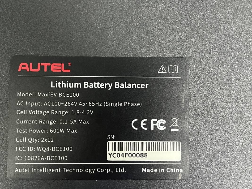
WQ8-BCE100
Jun 26, 2024LITHIUM BATTERY BALANCER
Equipment Class
DTS - Digital Transmission System
WQ8-ALT100L
Apr 01, 2024Battery Leakage Tester
Equipment Class
DTS - Digital Transmission System
WQ8-SK2311
Feb 19, 2024UNIVERSAL SMART KEY
Equipment Class
DSC - Part 15 Security/Remote Control TransmitterWQ8-DA2211
Jan 23, 2024ADAS Calibration Frame
Equipment Class
DSS - Part 15 Spread Spectrum Transmitter