WQ8-DR2014DIAGNOSTIC/SERVICE SCAN TOOL
Autel Intelligent Technology Corp., Ltd.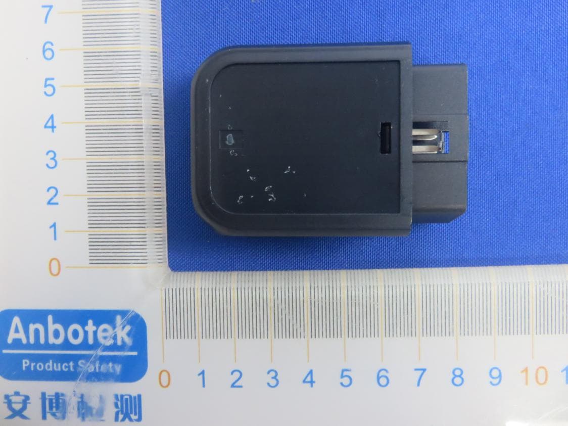
Click to zoom
Application Details
- Equipment Class
- DTS - Digital Transmission System
- Date of Grant
- May 21, 2021
- Application Purpose
- Original Equipment
- Date of Application
- May 21, 2021
- Equipment Note
- DIAGNOSTIC/SERVICE SCAN TOOL
- Frequency Range
- 2402.00000000 - 2480.00000000
- Country
- China
Documents & Files
Document Text
Text extracted from the exhibit documents filed with the FCC. Open a document above to read the original.
Users Manual
AUTEL. Web: www.autel.com MaxiAP AP2500 Quick Reference Guide M axiAP AP2500 _ 固 AUTEL ` 。 � AUTEL ® Thank you for purchasing this AUTEL tool. Manufactured to a high standard, our tool will, if used according to these instructions and properly maintained, give you years of trouble-free performance Getting Started oIMPORTANT: Before operating this unit, please read these instructions and the user manual carefully and pay extra attention to the safety warnings and precautions. Please use this unit as instructed. Failure to do so may cause damage and/or personal 叮uryand will void the product warranty 0NOTE: The images and illustrations depicted in this quick guide may differ slightly from the actual ones. The user interfaces for iOS & Android devices might be slightly different. The screenshots in this quick guide are captured from the iOS device app 0-- 穸 ' , . 。 繇 AUTEL Download & install app I I Register & log in • Scan the QR code or search for Autel Link• Open the Auta Link app叩tap Register 1n App Store or Google Play to download and ;nstaJI the app to your devK:e. on the"'-'妇l •Follow the on-screen ,nst,u哎ions to c.u,"佐le the回b归l回l. •Log in w ith your registered emal address/ phone number and password Add the dongle •On the M�n Job, tap Me> Device Manag er> Binding Equipment, the de•ice will aut� 归ticall;jump to the next screen. • Tap to scan the QR code ,mpnnted on the Bluetooth dongle or add the dongle by “心 一II!.- Bind VCI with device • After the scanning Is complete and the sen� number�automat,cal�retneved, 也p the Bind Equipment button at the bottom of the Interface to函odonglewith device 二 ` Find 08011 Port 气』 VCIConn纪tlO<l For both Android and IOS de邓ces,tap Me> Device Manager> AP2500 to笼r t诧dongle 咖your device. For衮devices,tap Settings > Bluetooth on your IOS device to open the Bluetooth funct,on. Then tap the Bluetooth name on the screen to p抽,t w;1h the d的ce. Toe Bluetooth name starts with死followedby the senaJ n叩berof the dongle. • Ensure your de心'sBluet如•turnedon • Whent沺device,s•,,rr,o呤吵wred w,th t诧dongle,the LED on the too w,11 l�ht sold blue. Flnish In如llation • Your Max囚P氏2500dongle is now ready for use , , 歹 气 乡 Key On, Engine Off Plug the connecto, of the Bluetoofh dong趴nto Tum the vehlcie lgn"1on to K"f On, Engine the veh心's08011 port. Off印执ion. • The ve改扣'sOBOllportls尹旧�I/located • The LED on the dongle wlll llght solid g心沪 u志the面lcleu必,w如(Consult面de wh旬connected userm可ualforot:心,fi氐妇;at切). UPDATE Software: When a new version is available, an Update button will display. Tap the button to update the software. VCI Firmware: Tap Me > Device Manager > AP2500 > Firmware Upgrade to update the firmware ff a new version is available For service and support, please contact us http://pro.autel.com I www.autel.com I [email protected] 0086-755-2267-2493 (China HQ) 11-855-AUTEL-US (288-3587) (North Amenca) 0049 (0) 6103-2000520 (Europe)/ -t-045 5948465 (APAC) I +971 585 002709 (IMEA) ©Autel Intelligent Technology Corp., Ltd. All Rights Reserved. NOTE: The interfaces in this quick guide are for reference only. DIAGNOSTIC/SERVICE SCAN TOOL FCC STATEMENT : This device complies with Part 15 of the FCC Rules. Operation is subject to the following two conditions: (1)This device may not cause harmful interference, and (2)This device must accept any interference received, including interference that may cause undesired operation. Warning: Changes or modifications not expressly approved by the party responsible for compliance could void the user's authority to operate the equipment. NOTE: This equipment has been tested and found to comply with the limits for a Class B digital device, pursuant to Part 15 of the FCC Rules. These limits are designed to provide reasonable protection against harmful interference in a residential installation. This equipment generates uses and can radiate radio frequency energy and, if not installed and used in accordance with the instructions, may cause harmful interference to radio communications. However, there is no guarantee that interference will not occur in a particular installation. If this equipment does cause harmful interference to radio or television reception, which can be determined by turning the equipment off and on, the user is encouraged to try to correct the interference by one or more of the following measures: Reorient or relocate the receiving antenna. Increase the separation between the equipment and receiver. Connect the equipment into an outlet on a circuit different from that to which the receiver is connected. Consult the dealer or an experienced radio/TV technician for help. FCC Radiation Exposure Statement: This equipment complies with FCC radiation exposure limits set forth for an uncontrolled environment. This equipment should be installed and operated with minimum distance 20cm between the radiator & your body. 对折来料
External Photos
FCCID:WQ8-DR2014
ID Label/Location Info
LabelLocationOnEUT Label ProductName:DIAGNOSTIC/SERVICESCANTOOL ModelNo.:MaxiAPAP2500 FCCID:WQ8-DR2014 ThisdevicecomplieswithPart15oftheFCCRules.Operation issubjecttothefollowingtwoconditions: (1)Thisdevicemaynotcauseharmfulinterference,and (2)Thisdevicemustacceptanyinterferencereceived,including interferencethatmaycauseundesiredoperation.
Internal Photos
FCCID:WQ8-DR2014 ANT
Operational Description
version01 AutelIntelligentTech.Corp.,Ltd. DeclarationconcerningAntennaSpecification Itisherebydeclaredthattheproduct ModelNo.:MaxiAPAP2500 FCCID:WQ8-DR2014 fulfillstherequirementinFCCtestrelatingtotheantennatype. ThedevicespecifiedaboveconfirmstotheFCCrecommendationsfor internal antennatype(s) describedbelow: BDR,EDR: ModelNo.ofantenna:N/A Typeofantenna:PCBAntenna Gainoftheantenna:0dBi Frequencyrange: 2402MHz~2480MHz BLE: ModelNo.ofantenna:N/A Typeofantenna:PCBAntenna Gainoftheantenna:0dBi Frequencyrange: 2402MHz~2480MHz Themountingoftheantennaisfixedtotheradiomoduleandnootherantennashouldbeused. Companyname:AutelIntelligentTech.Corp.,Ltd. Address:7th-8th,10thFloor,Bldg.B1,Zhiyuan,XueyuanRd.Xili,Nanshan,Shenzhen, China City:Shenzhen ZIP/Postalcode:518110 Country:Chin Place:Shenzhen,China Date:5/22/2021 Signature:
RF Exposure Info
RFEXPOSUREEVALUATION FCCID:WQ8-DR2014 AccordingtoFCC1.1310:Thecriterialistedinthefollowingtableshallbeused toevaluatetheenvironmentimpactofhumanexposuretoradiofrequency(RF) Radiationasspecifiedin§1.1307(b): RoutineSARevaluationreferstothatspecificallyrequiredby§2.1093,using measurementsorcomputersimulation.WhenroutineSARevaluationisnot required,portabletransmitterswithoutputpowergreaterthantheapplicable lowthresholdrequireSARevaluationtoqualifyforTCBapproval. Channel (MHz) Maximum output power (dBm) Tuneup tolerance (dBm) MaxTuneUp Power(dBm) Distance (mm) Calculation results Limit Operating Mode 2402 -0.009 -0.009±1 0.99150.3893 BDR+EDR 2441 0.5750.575±11.57550.4493 2480 1.1071.107±12.10750.5123 2402 0 00±1 150.3903 2441 0.5900.590±11.5950.4513 24801.1341.134±12.13450.5153 2402-0.190 -0.190±1 0.8150.3743 BLE24400.3920.392±11.39250.4313 24800.9940.994±11.99450.4983 TestResults:PASS.
Test Report
Report No.: 18220WC10046202FCC ID: WQ8-DR2014Page 1 of 41 Code:AB-RF-05-a FCC TEST REPORT Client Name: Autel Intelligent Tech. Corp., Ltd. Address: 7th-8th, 10th Floor, Bldg. B1, Zhiyuan, Xueyuan Rd. Xili, Nanshan, Shenzhen, China Product Name: DIAGNOSTIC/SERVICE SCAN TOOL Date: May 20, 2021 Shenzhen Anbotek Compliance Laboratory Limited Report No.: 18220WC10046202FCC ID: WQ8-DR2014Page 2 of 41 Code:AB-RF-05-a Contents 1. General Information ............................................................................................................................................... 5 1.1. Client Information ....................................................................................................................................... 5 1.2. Description of Device (EUT) ..................................................................................................................... 5 1.3. Auxiliary Equipment Used During Test ................................................................................................... 7 1.4. Description of Test Modes ........................................................................................................................ 7 1.5. List of channels ........................................................................................................................................... 7 1.6. Description Of Test Setup ......................................................................................................................... 8 1.7. Test Equipment List .................................................................................................................................... 9 1.8. Measurement Uncertainty ....................................................................................................................... 10 1.9. Description of Test Facility ...................................................................................................................... 10 2. Summary of Test Results ................................................................................................................................... 11 3. Conducted Emission Test ................................................................................................................................... 12 3.1. Test Standard and Limit .......................................................................................................................... 12 3.2. Test Setup .................................................................................................................................................. 12 3.3. Test Procedure .......................................................................................................................................... 12 3.4. Test Data .................................................................................................................................................... 12 4. Radiation Spurious Emission and Band Edge ................................................................................................ 17 4.1. Test Standard and Limit .......................................................................................................................... 17 4.2. Test Setup .................................................................................................................................................. 17 4.3. Test Procedure .......................................................................................................................................... 18 4.4. Test Data .................................................................................................................................................... 19 5. Maximum Peak Output Power Test .................................................................................................................. 27 5.1. Test Standard and Limit .......................................................................................................................... 27 5.2. Test Setup .................................................................................................................................................. 27 5.3. Test Procedure .......................................................................................................................................... 27 5.4. Test Data .................................................................................................................................................... 27 6. 6DB Occupy Bandwidth Test ............................................................................................................................. 30 6.1. Test Standard and Limit .......................................................................................................................... 30 6.2. Test Setup .................................................................................................................................................. 30 6.3. Test Procedure .......................................................................................................................................... 30 6.4. Test Data .................................................................................................................................................... 30 7. Power Spectral Density Test .............................................................................................................................. 33 7.1. Test Standard and Limit .......................................................................................................................... 33 7.2. Test Setup .................................................................................................................................................. 33 7.3. Test Procedure ...............................................................................................................................…
Text truncated - open the document above for the full version.
Test Setup Photos
FCCID:WQ8-DR2014 PhotoofPowerLineConductedEmissionTest PhotoofRadiationEmissionTest
Contact Information
Applicant
Frank Li(President)
Test Firm
Shenzhen Anbotek Compliance Laboratory LimitedJeff Zhu
Technical Specifications
| # | Rule Parts | Frequency Range | Power Output |
|---|---|---|---|
| 1 | 15C | 2.40 GHz - 2.48 GHz | 1.26 mW |
Other Applications from Autel Intelligent Technology Corp., Ltd.
WQ8-DV2121
Sep 05, 2025AUTOMOTIVE DIAGNOSIS & ANALYSIS SYSTEM
Equipment Class
DTS - Digital Transmission System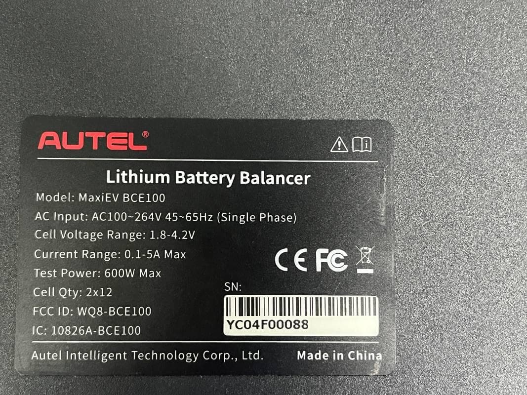
WQ8-BCE100
Jun 26, 2024LITHIUM BATTERY BALANCER
Equipment Class
DTS - Digital Transmission System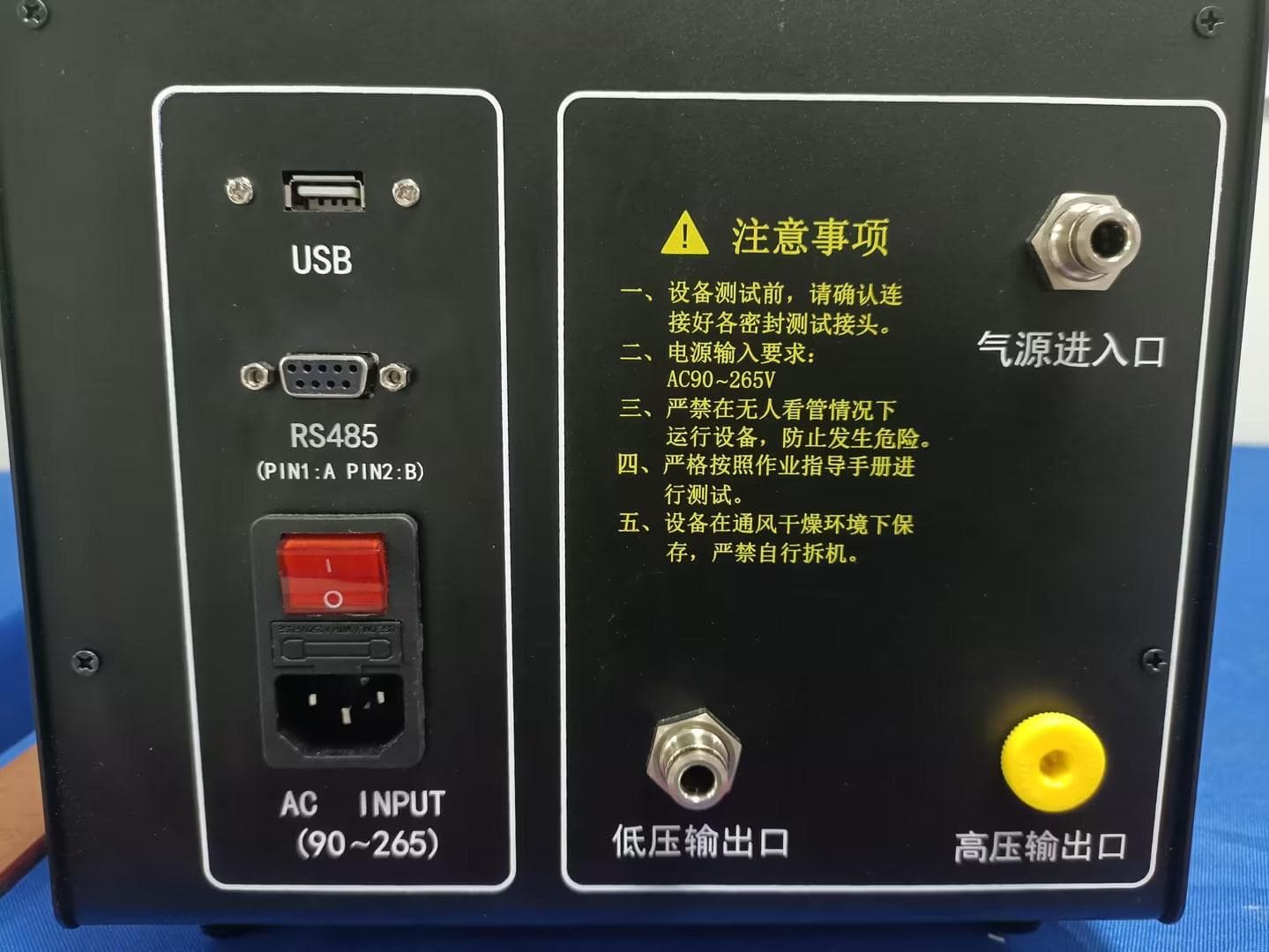
WQ8-ALT100L
Apr 01, 2024Battery Leakage Tester
Equipment Class
DTS - Digital Transmission System
WQ8-SK2311
Feb 19, 2024UNIVERSAL SMART KEY
Equipment Class
DSC - Part 15 Security/Remote Control TransmitterWQ8-DA2211
Jan 23, 2024ADAS Calibration Frame
Equipment Class
DSS - Part 15 Spread Spectrum Transmitter