WQ8-MS906PRO-TSAUTOMOTIVE DIAGNOSIS & ANALYSIS SYSTEM
Autel Intelligent Technology Corp., Ltd.
Click to zoom
Application Details
- Equipment Class
- DSS - Part 15 Spread Spectrum Transmitter
- Date of Grant
- Jul 20, 2021
- Application Purpose
- Original Equipment
- Date of Application
- Jul 20, 2021
- Equipment Note
- AUTOMOTIVE DIAGNOSIS & ANALYSIS SYSTEM
- Frequency Range
- 2402.00000000 - 2480.00000000
- Country
- China
Documents & Files
Document Text
Text extracted from the exhibit documents filed with the FCC. Open a document above to read the original.
Users Manual
0 IMPORTANT: Before operating or maintaining this unit, please read these instructions carefully, paying extra attention to the safety warnings and precautions. Failure to use this product properly may cause damage and/or personal injury and will void the product warranty. • Insert the Vehicle Data Connector on the MaxiVCI V200 into the veh1 一 cle's DLC, which is generally located under the vehicle dashboard. □- • Pair the tablet with the MaxiVCI V200 via Bluetooth to establish a communication link. 区NOTE:The tablet and the MaxiVCI V200 are configured to auto matically synchronize with each other on first use, so there should be no need to pair up. • When the MaxiVCI V200 is properly connected to the vehicle and the tablet, the VCI status button on the bottom bar of the screen will display a green badge with a check mark at the corner indicat ing the tablet is ready to start vehicle diagnosis. 詹 • Ensure the tablet is sufficiently charged or is connected to the supplied DC power suppl y. • Power up the tablet. 。 Alternatively, connect the tablet and the MaxiVCI V200 using the USB cable. • Hold the MaxiSys MS906 Pro-TS tablet with its top right corner close to the tire sidewall at the valve stem to activate the TPMS sensor. FCC Statement: 15.21 Information to user. Any Changes or modifications not expressly approved by the party responsible for compliance could void the user's authority to operate the equipment. 15.105 Information to user. This equipment has been tested and found to comply with the limits for a Class B digital device, pursuant to Part 15 of the FCC Rules. These limits are designed to provide reasonable protection against harmful interference in a residential installation. This equipment generates uses and can radiate radio frequency energy and, if not installed and used in accordance with the instructions, may cause harmful interference to radio communications. However, there is no guarantee that interference will not occur in a particular installation. If this equipment does cause harmful interference to radio or television reception, which can be determined by turning the equipment off and on, the user is encouraged to try to correct the interference by one or more of the following measures: • Reorient or relocate the receiving antenna. • I ncrease the separation between the equipment and receiver. • C onnect the equipment into an outlet on a circuit different from that to which t he receiver is connected. • C onsult the dealer or an experienced radio/TV technician for help. Specific Absorption Rate (SAR) information: This product meets the government's requirements for exposure t o radio waves. The guidelines are based on standards that were developed by independent scientific organizations through periodic and thorough evaluatio n of scientific studies. The standards include a substantial safety margin designed to assure the safety of all persons regardless of age or health. FCC RF Exposure Information and Statement The SAR limit of USA (FCC) is 1.6 W/kg averaged over one gram of tissue. This device was test ed for typical body-worn operations with the back of the handset kept 5mm from the body. To maintain compliance with FCC RF exposure requirements, use accessories that maintain a 5mm separation distance between the user's body and the back of the handset. The use of belt clips, holsters and similar accessories should not contain metallic components in its assembly. The use of accessories that do not satisfy these requirements may not comply with FCC RF exposure requirements, and should be avoided. Body-worn Operation This device was tested for typical body-worn operations. To comply with RF exposure requirements, a minimum separation distance of 5mm for body worn must be maintained between the user’s body, including the antenna. Third-party belt-clips, holsters, and similar accessories used by this device should not contain any metallic components. Body-worn accessories that do not meet these requirements may not comply with RF exposure requirements and s hould be avoided. Use only the supplied or an approved antenna.
Cover Letter(s)
AutelIntelligentTech.Corp.,Ltd. AgentAuthorizationLetter (2021-07-06) RE:LETTEROFAGENTAUTHORIZATION ToWhomItMayConcern: We,authorizeMicomLabsInc.,575BoulderCourt,Pleasanton,California94566, USAtoactonourbehalfinallmattersrelatingtoapplicationforequipment authorization,includingthesigningofalldocumentsrelatingtothesematters. Thisagreementexpiresoneyearfromthecurrentdate. Sincerely, FrankLi/Manager/ CompanyName:AutelIntelligentTech.Corp.,Ltd. Address:7th-8th,10thFloor,Bldg.B1,Zhiyuan,XueyuanRd.Xili,NanshanShenzhen China
Cover Letter(s)
Autel Intelligent Tech. Corp., Ltd. Office of Engineering Technology Federal Communications Commission 7435 Oakland Mills Road Columbia, MD 21046 USA Date: 2021-07-06 Subject; Request for Confidentiality FCC ID: WQ8-MS906PRO-TS To Whom It May Concern, Pursuant to the provisions of the Commission’s rules Title 47 Sections §0.457 and §0.459, we are requesting the Commission to withhold the following attachment(s) as confidential documents from public disclosure indefinitely. These documents contain detailed system and equipment descriptions and are considered as proprietary information in operation of the equipment. The public disclosure of these documents might be harmful to our company and would give competitors an unfair advantage in the market. Schematic Diagram Block Diagram Operational Description SW SECURITY DESCRIPTION In additional to above mentioned documents, in order to comply with the marketing regulations in Title 47 CFR §2.803 and the importation rules in Title 47 CFR §2.1204, while ensuring that business sensitive information remains confidential until the actual marketing of newly authorized devices, we request Short Term Confidentiality of the following attachment(s); External Photos Test Setup Photos Internal Photos User Manual For 45 days, pursuant to Public Notice DA 04-1705. OR For 180 days pursuant to KDB 726920 D01. It is our understanding that all measurement test reports, FCC ID label format and correspondence during the certification review process cannot be granted as confidential documents and this information will be available for public review once the grant of equipment authorization is issued. Sincerely, Signature: Name: Frank Li Title: Manager
External Photos
FCCID:WQ8-MS906PRO-TS
ID Label/Location Info
LabelLocation: Label: ProductName:AUTOMOTIVEDIAGNOSIS&ANALYSISSYSTEM ModelNo.:MS906Pro-TS FCCID:WQ8-MS906PRO-TS ThisdevicecomplieswithPart15oftheFCCRules.Operationissubjecttothefollowingtwo conditions: (1)Thisdevicemaynotcauseharmfulinterference,and (2)Thisdevicemustacceptanyinterferencereceived,includinginterferencethatmaycause undesiredoperation.
Test Report
Report No.: 18220WC10072601FCC ID: WQ8-MS906PRO-TSPage 1 of 69 Code:AB-RF-05-a FCC TEST REPORT Client Name:Autel Intelligent Tech. Corp., Ltd. Address: 7th-8th, 10th Floor, Bldg. B1, Zhiyuan,Xueyuan Rd. Xili, Nanshan Shenzhen China Product Name:AUTOMOTIVE DIAGNOSIS & ANALYSIS SYSTEM Date:Jul. 06, 2021 Shenzhen Anbotek Compliance Laboratory Limited Report No.: 18220WC10072601FCC ID: WQ8-MS906PRO-TSPage 2 of 69 Code:AB-RF-05-a Contents 1. General Information ............................................................................................................................................... 5 1.1. Client Information ....................................................................................................................................... 5 1.2. Description of Device (EUT) ..................................................................................................................... 5 1.3. Auxiliary Equipment Used During Test ................................................................................................... 7 1.4. Description of Test Modes ........................................................................................................................ 7 1.5. List of channels ........................................................................................................................................... 8 1.6. Description Of Test Setup ......................................................................................................................... 9 1.7. Test Equipment List .................................................................................................................................. 10 1.8. Measurement Uncertainty ....................................................................................................................... 11 1.9. Description of Test Facility ...................................................................................................................... 11 2. Summary of Test Results ................................................................................................................................... 12 3. Conducted Emission Test ................................................................................................................................... 13 3.1. Test Standard and Limit .......................................................................................................................... 13 3.2. Test Setup .................................................................................................................................................. 13 3.3. Test Procedure .......................................................................................................................................... 13 3.4. Test Data .................................................................................................................................................... 13 4. Radiation Spurious Emission and Band Edge ................................................................................................ 18 4.1. Test Standard and Limit .......................................................................................................................... 18 4.2. Test Setup .................................................................................................................................................. 18 4.3. Test Procedure .......................................................................................................................................... 19 4.4. Test Data .................................................................................................................................................... 20 5. Maximum Peak Output Power Test .................................................................................................................. 28 5.1. Test Standard and Limit .......................................................................................................................... 28 5.2. Test Setup .................................................................................................................................................. 28 5.3. Test Procedure .......................................................................................................................................... 28 5.4. Test Data .................................................................................................................................................... 28 6. 20DB Occupy Bandwidth Test ........................................................................................................................... 32 6.1. Test Standard ............................................................................................................................................ 32 6.2. Test Setup .................................................................................................................................................. 32 6.3. Test Procedure .......................................................................................................................................... 32 6.4. Test Data .................................................................................................................................................... 32 7. Carrier Frequency Separation Test ................................................................................................................... 36 7.1. Test Standard and Limit .......................................................................................................................... 36 7.2. Test Setup .................................................................................................................................................. 36 7.3. Test Procedure ...............................................................................................................…
Text truncated - open the document above for the full version.
Test Setup Photos
PHOTOS OF TEST SETUP FCC ID: WQ8-MS906PRO-TS Photo of Conducted Emission Measurement Photo of Radiation Emission Test
Contact Information
Applicant
Frank Li(President)
Technical Contact
Test Firm
Shenzhen Anbotek Compliance Laboratory LimitedJeff Zhu
Technical Specifications
| # | Rule Parts | Frequency Range | Power Output |
|---|---|---|---|
| 1 | 15C | 2.40 GHz - 2.48 GHz | 2.90 mW |
Other Applications from Autel Intelligent Technology Corp., Ltd.
WQ8-DV2121
Sep 05, 2025AUTOMOTIVE DIAGNOSIS & ANALYSIS SYSTEM
Equipment Class
DTS - Digital Transmission System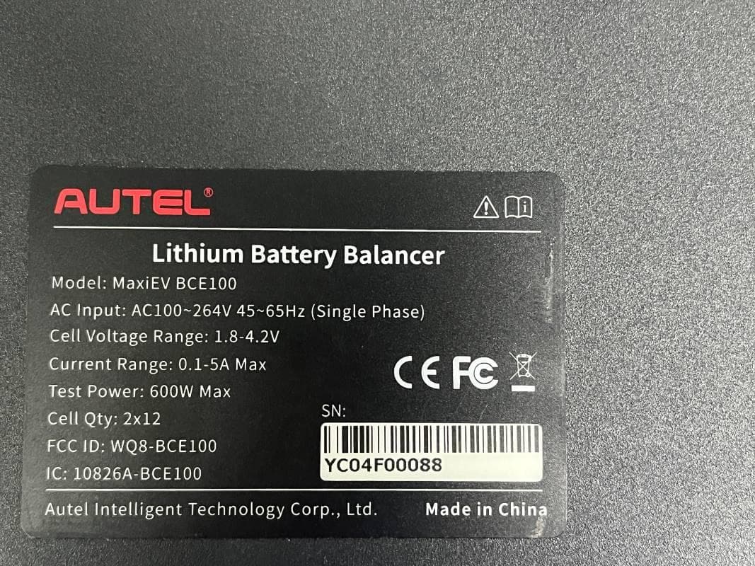
WQ8-BCE100
Jun 26, 2024LITHIUM BATTERY BALANCER
Equipment Class
DTS - Digital Transmission System
WQ8-ALT100L
Apr 01, 2024Battery Leakage Tester
Equipment Class
DTS - Digital Transmission System
WQ8-SK2311
Feb 19, 2024UNIVERSAL SMART KEY
Equipment Class
DSC - Part 15 Security/Remote Control TransmitterWQ8-DA2211
Jan 23, 2024ADAS Calibration Frame
Equipment Class
DSS - Part 15 Spread Spectrum Transmitter