WQ8-MXVCIV100MaxiVCI V100
Autel Intelligent Technology Corp., Ltd.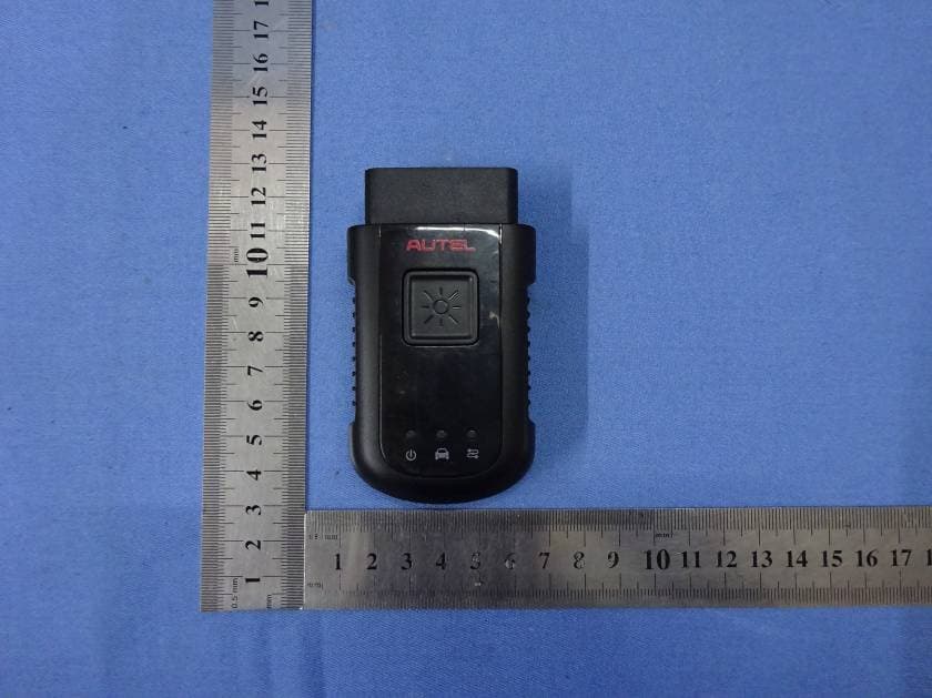
Click to zoom
Application Details
- Equipment Class
- DSS - Part 15 Spread Spectrum Transmitter
- Date of Grant
- Dec 12, 2015
- Application Purpose
- Original Equipment
- Date of Application
- Dec 12, 2015
- Equipment Note
- MaxiVCI V100
- Frequency Range
- 2402.00000000 - 2480.00000000
- Country
- China
Documents & Files
Document Text
Text extracted from the exhibit documents filed with the FCC. Open a document above to read the original.
Users Manual
Table of Contents General Notice ........................................................... 1 Introduction .............................................................. 2 Functional Description .............................................. 4 Product Troubleshooting .......................................... 8 Driver Setup .............................................................. 9 Firmware Update ..................................................... 12 Compliance Information .......................................... 14 Warranty And Service .............................................. 16 1 General Notice The wireless diagnostic interface MaxiVCI V100 has been carefully designed and tested to comply with OBDII protocols. However, some vehicle models are not in full compliance with these protocols for various reasons. In addition, the computer control systems or sensors on any given vehicle may be malfunctioning. While Autel’s testing and the experiences of the users have shown the unit to be safe and reliable, there is an inherent risk in using any product that may potentially affect the operation or drive-ability of your vehicle. If you are concerned about the operation of your vehicle at any time while using the MaxiVCI V100: Pull off the roadway immediately or as soon as it is safe to do so. Disconnect the device from the OBDII port. Consult a licensed mechanic or automobile service center. Contact your local distributor, or visit www.autel.com for issues or concerns about the product. We maintain an active database of the feedback we receive, and your comments can help us continuously improve the product. 2 Introduction The wireless diagnostic interface MaxiVCI V100 is a small interface box used to connect to a vehicle’s diagnostic connector (DLC) and connect wirelessly with the MaxiSys Display Tablet, as well as standalone PC, as a vehicle communication interface (VCI) for vehicle data transmission. Thanks to the wireless BT technology, with which you are allowed to work freely around the vehicle. The MaxiVCI V100 can communicate with vehicles’ electronic control units (ECUs), guaranteeing performance and speed that redefine multi-brand diagnostics. The development of this interface has been focused on reducing the communication time, and ensuring the tool is practical to use. The MaxiSys diagnostic platform combines the MaxiVCI V100 and the display tablet with technical information into a single program, ensuring quick and simple access to the vehicle to perform comprehensive diagnostics applications. 3 Wireless Communication The MaxiVCI V100 supports BT communication. It can transmit vehicle data to the MaxiSys Display Tablet without a physical connection. The working range of the transmitter through BT communication is about 164 feet (about 50 m). A signal lost due to moving out of range automatically restores itself when the display unit is brought closer to the MaxiVCI V100 unit. USB Connectivity The MaxiVCI V100 also provides a direct connection to the MaxiSys Display Tablet or a PC via a USB 2.0 full-speed connection. All of the electronics are contained in the device shell, making it a compact and rugged vehicle communication tool. Power Source The MaxiVCI V100 operates on 12-volt vehicle power, which it receives through the vehicle data connection port. The unit powers on whenever it is connected to an OBD II/EOBD compliant data link connector (DLC). It can also be powered through connection with a PC via the USB cable, so there’s no need to connect the device to the vehicle when performing firmware update through the PC. 4 Functional Description The MaxiVCI V100 device package includes the unit, user manual, and a CD with driver program and update agent. 1. Lighting Push Button 2. Power LED 3. Vehicle LED 4. Connection LED 5. Vehicle Data Connector (16-Pin) 6. USB Port Lighting Push Button Press the lighting push button to turn on the white LED in the vehicle data connector socket. 5 Status LEDs There are 3 status LEDs on the front panel of the MaxiVCI V100, which indicates its working status as well as the hardware conditions, and are very useful for troubleshooting the device’s communication or connection to the vehicle, display tablet and/or the PC. See Table 1 for detailed description of the status LEDs. Table 1 – Status LEDs on the Front Panel LED Color Description Power Green Illuminates solid green when powered on. Amber The power LED flashes green and amber automatically when performing firmware update. Red Flashes red when system failure occurs. Note: The power LED illuminates red automatically every time when the device is power up, which is a normal self-test procedure, and it will turn green automatically later when the device starts working normally. Vehicle Green Flashes green when communicating with the vehicle’s system. Connection Green Illuminates solid green when properly connected with the display tablet or the PC via the USB cable Blue Illuminates solid blue when connected with the display tablet via wireless (BT) connection Vehicle Data Connector The vehicle connector connects the MaxiVCI V100 to the vehicle’s 16-pin DLC directly. 6 USB Port The USB port provides the easiest connection between the device and the display tablet or the PC via a USB cable, and is used to control the device from the software application running on the PC. Technical Specifications Item Description Communications BT V.2.1 + EDR USB 2.0 Wireless Frequency 2.4 GHz Input Voltage Range 12 VDC Supply Current 150 mA @ 12 VDC Operating Temperature 0°C to 50°C (ambient) Storage Temperature -20°C to 70°C (ambient) Dimensions (L x W x H) 87 mm (3.43”) x 52 mm (2.05”) x 24.5 mm (0.96”) Weight 0.076 kg (0.168 lb.) Built-in Battery 3.7V Lithium Battery Light White LED Capabilities When used in conjunction with the display table or the OEM softwares from the PC, the MaxiVCI V100 is able to perform the following functions: Auto diagnostics to read and clear the error m…
Text truncated - open the document above for the full version.
Cover Letter(s)
Autel Intelligent Tech. Corp., Ltd. 6th - 10th Floor, Bldg. B1, Zhiyuan, Xueyuan Rd., Xili, Nanshan Shenzhen China DATE :2015-10-29 Nemko Canada Inc 303 River Road Ottawa, Ontario, Canada K1V 1H2 Attn: Director of Certification Authority to Act as Agent On our behalf, I appoint Hank.Yan of Global United Technology Services Co., Ltd. 2nd Floor, Block No.2, Laodong Industrial Zone, Xixiang Road Baoan District Shenzhen Guangdong to act as our agent in the preparation of this application for equipment certification. I certify that submitted documents properly describe the device or system for which equipment certification is sought. I also certify that each unit manufactured, imported or marketed, as defined in the Federal Communications Commission’s regulations will have affixed to it a label identical to that submitted for approval with this application. For instances where our authorized agent signs the application for certification on our behalf, I acknowledge that all responsibility for complying with the terms and conditions for certification, as specified by Nemko Canada Inc, still resides with Autel Intelligent Tech. Corp., Ltd. and 6th - 10th Floor, Bldg. B1, Zhiyuan, Xueyuan Rd., Xili, Nanshan Shenzhen China Dated this / Day of 10/29/2015 / Agency agreement expiration date: 10/29/2016 By: Frank Li Signature Printed Title: President On behalf of : Autel Intelligent Tech. Corp., Ltd. Telephone: (86)755-86147779
Cover Letter(s)
Date: 10/29/2015 To: Federal Communications Commission 7435 Oakland Mills Road Columbia, MD FCC ID: WQ8-MXVCIV100 To Whom It May Concern: We,Autel Intelligent Tech. Corp., Ltd., are applying FCC DOC for product MaxiVCI V100 which model no. is MaxiVCI V100. the FCC DOC is doing at proper FCC authorized and recognized lab, and FCC DOC will be issued soon. If you have any question or concerns, pls. contact us. Sincerely, Client’s signature Client’s name / title Frank Li / President Contact information / address Tel: (86)755-86147779 Address: 6th - 10th Floor, Bldg. B1, Zhiyuan, Xueyuan Rd., Xili, Nanshan Shenzhen China authorized and recognized MRA lab, and FCC DOC will be issued soon.
Cover Letter(s)
Autel Intelligent Tech. Corp., Ltd. 6th - 10th Floor, Bldg. B1, Zhiyuan, Xueyuan Rd., Xili, Nanshan Shenzhen China 2015-10-29 Equipment Authorization Division Federal Communications Commission 7435 Oakland Mills Road Columbia, MD 21046 FCC ID: WQ8-MXVCIV100 Product Name: MaxiVCI V100 Request for Confidentiality Pursuant to Sections 0.457 and 0.459 of the commissions rules, we hereby request that the following documents be held confidential: Schematics Block diagram Operational Description These materials contain trade secrets and proprietary information and are not customarily released to the public. The public disclosure of this information might be harmful to the company and provide unjustified benefits to our competitors. Dated this 10/29/2015 By: Frank Li Signature Printed Title: President On behalf of : Autel Intelligent Tech. Corp., Ltd. Telephone: (86)755-86147779
RF Exposure Info
FCC ID: WQ8-MXVCIV100 RF Exposure Evaluation Limits The criteria listed in the following table shall be used to evaluate the environment impact of human exposure to radio frequency (RF) radiation as specified in 1.1307(b) Limits for Maximum Permissible Exposure (MPE) Frequency range (MHz) Electric field strength (V/m) Magnetic field strength (A/m) Power density (mW/cm 2 ) Averaging time (minutes) (A) Limits for Occupational/Controlled Exposures 0.3–3.06141.63*(100)6 3.0–301842/f4.89/f*(900/f 2 )6 30–30061.40.1631.06 300–1500f/3006 1500–100,00056 (B) Limits for General Population/Uncontrolled Exposure 0.3–1.346141.63*(100)30 1.34–30824/f2.19/f*(180/f 2 )30 30–30027.50.0730.230 300–1500f/150030 1500–100,0001.030 f = frequency in MHz Friis transmission formula: Pd = (Pout*G)/(4*pi*r 2 ) Where Pd= power density in mW/cm 2 , Pout= output power to antenna in mW; G= gain of antenna in linear scale, Pi= 3.1416; R = distance between observation point and center of the radiator in cm Pd id the limit of MPE, 1 mW/cm 2 . If we know the maximum gain of the antenna and the total power input to the antenna, through the calculation, we will know the distance r where the MPE limit is reached. Test Procedure Software provided by client enabled the EUT to transmit and receive data at lowest, middle and highest channel individually. Test Result of RF Exposure Evaluation GFSK mode Channel Output power to antenna (mW) Power Density at R=20cm (mW/cm 2 ) Limit (mW/cm 2 ) Result Lowest (2402MHz) 15.849 0.00354 1.0PASS Middle (2441MHz) 18.621 0.00416 1.0PASS Highest (2480MHz) 14.997 0.00335 1.0PASS Pi/4QPSK mode Channel Output power to antenna (mW) Power Density at R=20cm (mW/cm 2 ) Limit (mW/cm 2 ) Result Lowest (2402MHz) 2.704 0.00060 1.0PASS Middle (2441MHz) 2.667 0.00060 1.0PASS Highest (2480MHz) 2.704 0.00060 1.0PASS 8DPSK mode Channel Output power to antenna (mW) Power Density at R=20cm (mW/cm 2 ) Limit (mW/cm 2 ) Result Lowest (2402MHz)2.382 0.00053 1.0PASS Middle (2441MHz)2.366 0.00053 1.0PASS Highest (2480MHz)2.234 0.00050 1.0PASS Remark: antenna gain=0.5 dBi Remark: Only worse case is reported Note:Antenna gain=0.5 dBi
Test Report
Global United Technology Services Co., Ltd. Report No.: GTSE15100194101 Authorized Signature: Robinson Lo Laboratory Manager This report details the results of the testing carried out on one sample. The results contained in this test report do not relate to other samples of the same product and does not permit the use of the GTS product certification mark. The manufacturer should ensure that all products in series production are in conformity with the product sample detailed in this report. This report may only be reproduced and distributed in full. If the product in this report is used in any configuration other than that detailed in the report, the manufacturer must ensure the new system complies with all relevant standards. Any mention of GTS or testing done by GTS in connection with, distribution or use of the product described in this report must be approved by GTS in writing. This document cannot be reproduced except in full, without prior written approval of the Company. Any unauthorized alteration, forgery or falsification of the content or appearance of this document is unlawful and offenders may be prosecuted to the fullest extent of the law. Unless otherwise stated the results shown in this test report refer only to the sample(s) tested and such sample(s) are retained for 90 days only. Robinson Lo 1Cover Page FCC Report(Bluetooth) Applicant: Autel Intelligent Tech. Corp., Ltd. Address of Applicant: 6th - 10th Floor, Bldg. B1, Zhiyuan, Xueyuan Rd., Xili, Nanshan Shenzhen China Equipment Under Test (EUT) Product Name:MaxiVCI V100 Model No.:MaxiVCI V100 Trade Mark:AUTEL FCC ID: WQ8-MXVCIV100 Applicable standards: FCC CFR Title 47 Part 15 Subpart C Section 15.247:2014 Date of sample receipt: October 20, 2015 Date of Test: October 21-28, 2015 Date of report issued: October 29, 2015 Test Result : PASS * * In the configuration tested, the EUT complied with the standards specified above. Report No.: GTSE15100194101 Global United Technology Services Co., Ltd.Project No.: GTSE151001941RF Room 301-309, 3th Floor, Block A, Huafeng Jinyuan Business Building, No. 300 Laodong Industrial Zone,Xixiang Road, Baoan District, Shenzhen 518102 Telephone: +86 (0) 755 2779 8480 Fax: +86 (0) 755 2779 8960Page 2 of 51 2Version Version No.DateDescription 00October 29, 2015Original Prepared By: Date: October 29, 2015 Project Engineer Check By:Date: October 29, 2015 Reviewer Report No.: GTSE15100194101 Global United Technology Services Co., Ltd.Project No.: GTSE151001941RF Room 301-309, 3th Floor, Block A, Huafeng Jinyuan Business Building, No. 300 Laodong Industrial Zone,Xixiang Road, Baoan District, Shenzhen 518102 Telephone: +86 (0) 755 2779 8480 Fax: +86 (0) 755 2779 8960Page 3 of 51 3Contents Page 1 COVER PAGE .......................................................................................................................................... 1 2 VERSION .................................................................................................................................................. 2 3 CONTENTS .............................................................................................................................................. 3 4 TEST SUMMARY ..................................................................................................................................... 4 4.1 MEASUREMENT UNCERTAINTY............................................................................................................. 4 5 GENERAL INFORMATION ...................................................................................................................... 5 5.1 CLIENT INFORMATION.......................................................................................................................... 5 5.2 GENERAL DESCRIPTION OF EUT ......................................................................................................... 5 5.3 TEST MODE........................................................................................................................................ 7 5.4 TEST FACILITY.................................................................................................................................... 7 5.5 TEST LOCATION.................................................................................................................................. 7 5.6 OTHER INFORMATION REQUESTED BY THE CUSTOMER......................................................................... 7 5.7 DESCRIPTION OF SUPPORT UNITS....................................................................................................... 7 6 TEST INSTRUMENTS LIST ..................................................................................................................... 8 7 TEST RESULTS AND MEASUREMENT DATA...................................................................................... 9 7.1 ANTENNA REQUIREMENT..................................................................................................................... 9 7.2 CONDUCTED PEAKOUTPUT POWER.................................................................................................. 10 7.3 20DBEMISSION BANDWIDTH............................................................................................................. 14 7.4 CARRIER FREQUENCIES SEPARATION................................................................................................ 18 7.5 HOPPING CHANNEL NUMBER............................................................................................................. 22 7.6 DWELL TIME..................................................................................................................................... 23 7.7 PSEUDORANDOM FREQUENCY HOPPING SEQUENCE.......................................................................... 25 7.8 BAND EDGE...........................................................................................................................…
Text truncated - open the document above for the full version.
Test Setup Photos
Radiated Emission
Contact Information
Applicant
Frank Li(President)
Test Firm
Global United Technology Service Co., LtdRobinson Lo
Technical Specifications
| # | Rule Parts | Frequency Range | Power Output |
|---|---|---|---|
| 1 | 15C | 2.40 GHz - 2.48 GHz | 18.62 mW |
Other Applications from Autel Intelligent Technology Corp., Ltd.
WQ8-DV2121
Sep 05, 2025AUTOMOTIVE DIAGNOSIS & ANALYSIS SYSTEM
Equipment Class
DTS - Digital Transmission System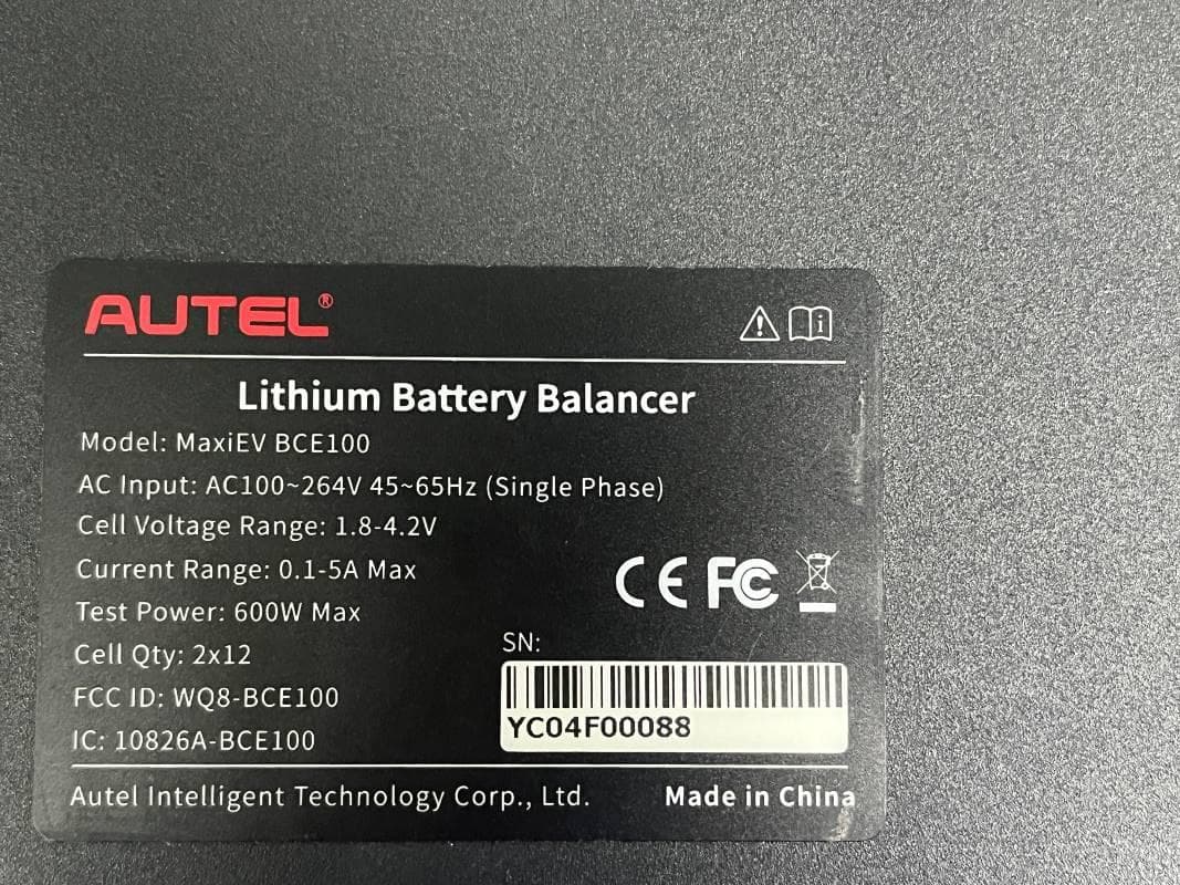
WQ8-BCE100
Jun 26, 2024LITHIUM BATTERY BALANCER
Equipment Class
DTS - Digital Transmission System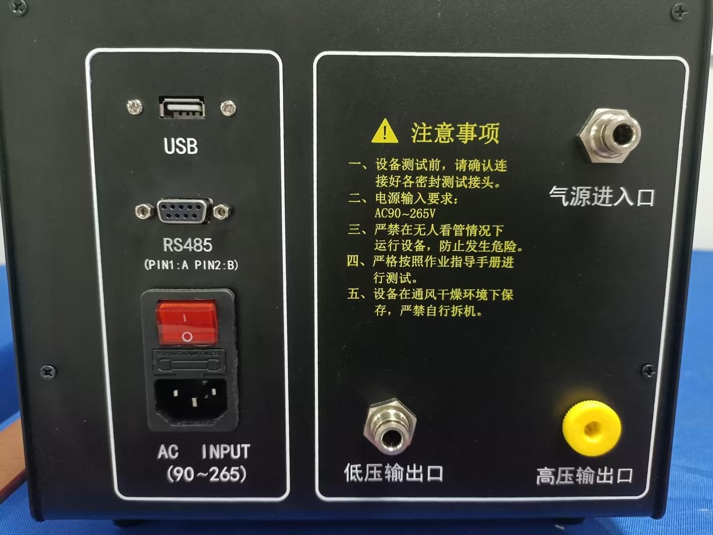
WQ8-ALT100L
Apr 01, 2024Battery Leakage Tester
Equipment Class
DTS - Digital Transmission System
WQ8-SK2311
Feb 19, 2024UNIVERSAL SMART KEY
Equipment Class
DSC - Part 15 Security/Remote Control TransmitterWQ8-DA2211
Jan 23, 2024ADAS Calibration Frame
Equipment Class
DSS - Part 15 Spread Spectrum Transmitter