WQ8301A315Universal Tire Pressure Monitoring Sensor
Autel Intelligent Technology Corp., Ltd.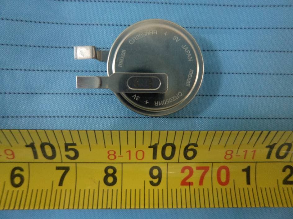
Click to zoom
Application Details
- Equipment Class
- DSC - Part 15 Security/Remote Control Transmitter
- Date of Grant
- Nov 20, 2013
- Application Purpose
- Original Equipment
- Date of Application
- Nov 20, 2013
- Equipment Note
- Universal Tire Pressure Monitoring Sensor
- Frequency Range
- 315.00000000 - 315.00000000
- Country
- China
Documents & Files
Document Text
Text extracted from the exhibit documents filed with the FCC. Open a document above to read the original.
Users Manual
FCC Caution: Any Changes or modifications not expressly approved by the party responsible for compliance could void the user's authority to operate the equipment. This device complies with part 15 of the FCC Rules. Operation is subject to the following two conditions: (1) This device may not cause harmful interference, and (2) this device must accept any interference received, including interference that may cause undesired operation. This equipment has been tested and found to comply with the limits for a Class B digital device,pursuant to part 15 of the FCC Rules. These limits are designed to provide reasonable protection against harmful interference in a residential installation. This equipment generates, uses and can radiate radio frequency energy and, if not installed and used in accordance with the instructions, may cause harmful interference to radio communications. However, there is no guarantee that interference will not occur in a particular installation. If this equipment does cause harmful interference to radio or television reception, which can be determined by turning the equipment off and on, the user is encouraged to try to correct the interference by one or more of the following measures: —Reorient or relocate the receiving antenna. —Increase the separation between the equipment and receiver. —Connect the equipment into an outlet on a circuit different from that to which the receiver is connected. —Consult the dealer or an experienced radio/TV technician for help. IC Waring This device complies with Industry Canada licence-exempt RSS standard(s). Operation is subject to the following two conditions: (1) this device may not cause interference, and (2) this device must accept any interference, including interference that may cause undesired operation of the device. Le présent appareil est conforme aux CNR d'Industrie Canada applicables aux appareils radio exempts de licence. L'exploitation est autorisée aux deux conditions suivantes: (1) l'appareil ne doit pas produire de brouillage, et (2) l'utilisateur de l'appareil doit accepter tout brouillage radioélectrique subi, même si le brouillage est susceptible d'en compromettre le fonctionnement. Under Industry Canada regulations, this radio transmitter may only operate using an antenna of a type and maximum (or lesser) gain approved for the transmitter by Industry Canada. To reduce potential radio interference to other users, the antenna type and its gain should be so chosen that the equivalent isotropically radiated power (e.i.r.p.) is not more than that necessary for successful communication. Conformément à la réglementation d'Industrie Canada, le présent émetteur radio peut fonctionner avec une antenne d'un type et d'un gain maximal (ou inférieur) approuvé pour l'émetteur par Industrie Canada. Dans le but de réduire les risques de brouillage radioélectrique à l'intention des autres utilisateurs, il faut choisir le type d'antenne et son gain de sorte que la puissance isotrope rayonnée équivalente (p.i.r.e.) ne dépasse pas l'intensité nécessaire à l'établissement d'une communication satisfaisante. Radiation Exposure Statement: This equipment complies with FCC/IC radiation exposure limits set forth for an uncontrolled environment. This equipment should be installed and operated with minimum distance 20cm between the radiator & your body. This transmitter must not be co-located or operating in conjunction with any other antenna or transmitter.
External Photos
EXHIBIT B - EUT EXTERNAL PHOTOGRAPHS EUT – Front View EUT – Rear View EUT – Top View EUT – Bottom View EUT – Left Side View EUT – Right Side View EUT – Battery View
Internal Photos
EXHIBIT C - EUT INTERNAL PHOTOGRAPHS EUT – Cover off View EUT – Main Board Top View Antenna EUT – Main Board Bottom View
Test Report
Note: This test report is prepared for the customer shown above and for the equipment described herein. It may not be duplicated or used in part without prior written consent from Bay Area Compliance Laboratories Corp. FCC PART 15.231 TEST REPORT For Shenzhen Autel Intelligent Tech. Co., Ltd. East Gate, the 1st Floor of SZICC Bldg., Chaguang Road 1089, Xili Town, Nanshan District, Shenzhen, China FCC ID: WQ8301A315 Report Type: Original Report Product Type: Universal Tire Pressure Monitoring Sensor Test Engineer: Gardon Zhang Report Number: RSZ130930003-00 Report Date: 2013-11-13 Reviewed By: Alvin Huang RF Leader Prepared By: Bay Area Compliance Laboratories Corp. (Shenzhen) 6/F, the 3rd Phase of WanLi Industrial Building, ShiHua Road, FuTian Free Trade Zone Shenzhen, Guangdong, China Tel: +86-755-33320018 Fax: +86-755-33320008 www.baclcorp.com.cn Bay Area Compliance Laboratories Corp. (Shenzhen) Report No.: RSZ130930003-00 FCC Part 15.231 Page 2 of 24 TABLE OF CONTENTS GENERAL INFORMATION.......................................................................................................................................3 PRODUCT DESCRIPTION FOR EQUIPMENT UNDER TEST (EUT) .....................................................................................3 OBJECTIVE...................................................................................................................................................................3 RELATED SUBMITTAL(S)/GRANT(S).............................................................................................................................3 TEST METHODOLOGY..................................................................................................................................................3 TEST FACILITY.............................................................................................................................................................3 SYSTEM TEST CONFIGURATION ..........................................................................................................................4 JUSTIFICATION.............................................................................................................................................................4 SPECIAL ACCESSORIES.................................................................................................................................................4 EQUIPMENT MODIFICATIONS.......................................................................................................................................4 BLOCK DIAGRAM OF TEST SETUP................................................................................................................................4 SUMMARY OF TEST RESULTS...............................................................................................................................5 FCC §15.203 - ANTENNA REQUIREMENT.............................................................................................................6 APPLICABLE STANDARD..............................................................................................................................................6 ANTENNA CONNECTOR CONSTRUCTION......................................................................................................................6 FCC §15.205, §15.209, §15.231 (B), §15.231 (E) - RADIATED EMISSIONS ..........................................................7 APPLICABLE STANDARD..............................................................................................................................................7 MEASUREMENT UNCERTAINTY....................................................................................................................................7 EUT SETUP..................................................................................................................................................................8 EMI TEST RECEIVER SETUP.........................................................................................................................................8 TEST PROCEDURE........................................................................................................................................................8 TEST EQUIPMENT LIST AND DETAILS...........................................................................................................................9 CORRECTED AMPLITUDE & MARGIN CALCULATION...................................................................................................9 TEST RESULTS SUMMARY..........................................................................................................................................10 TEST DATA................................................................................................................................................................10 FCC §15.231(C) – 20 DB EMISSION BANDWIDTH TESTING ...........................................................................17 APPLICABLE STANDARD............................................................................................................................................17 TEST EQUIPMENT LIST AND DETAILS.........................................................................................................................17 TEST PROCEDURE......................................................................................................................................................17 TEST DATA................................................................................................................................................................17 FCC §15.231(A)(2) - DEACTIVATION TESTING..................................................................................................20 APPLICABLE STANDARD...................................................................................................................…
Text truncated - open the document above for the full version.
Test Setup Photos
EXHIBIT D - TEST SETUP PHOTOGRAPHS Radiated Emission View (Below 1 GHz) Radiated Emission View (Above 1 GHz)
Contact Information
Applicant
Frank Li(President)
Test Firm
Bay Area Compliance Laboratory Corp. (Shenzhen)John Chan
Technical Specifications
| # | Rule Parts | Frequency Range | Power Output |
|---|---|---|---|
| 1 | 15.231,15.231(e) | 315 MHz - 315 MHz | - |
Other Applications from Autel Intelligent Technology Corp., Ltd.
WQ8-DV2121
Sep 05, 2025AUTOMOTIVE DIAGNOSIS & ANALYSIS SYSTEM
Equipment Class
DTS - Digital Transmission System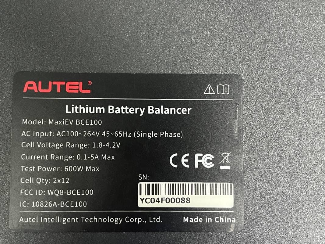
WQ8-BCE100
Jun 26, 2024LITHIUM BATTERY BALANCER
Equipment Class
DTS - Digital Transmission System
WQ8-ALT100L
Apr 01, 2024Battery Leakage Tester
Equipment Class
DTS - Digital Transmission System
WQ8-SK2311
Feb 19, 2024UNIVERSAL SMART KEY
Equipment Class
DSC - Part 15 Security/Remote Control TransmitterWQ8-DA2211
Jan 23, 2024ADAS Calibration Frame
Equipment Class
DSS - Part 15 Spread Spectrum Transmitter