WQ8TPMSDF88MX-SENSOR
Autel Intelligent Technology Corp., Ltd.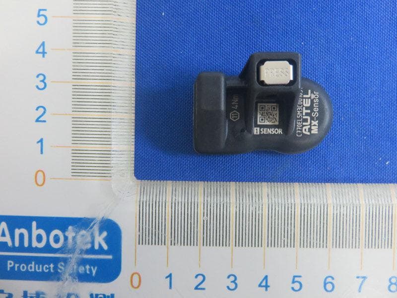
Click to zoom
Application Details
- Equipment Class
- DSC - Part 15 Security/Remote Control Transmitter
- Date of Grant
- Apr 14, 2021
- Application Purpose
- Original Equipment
- Date of Application
- Apr 14, 2021
- Equipment Note
- MX-SENSOR
- Frequency Range
- 433.92000000 - 433.92000000
- Country
- China
Documents & Files
Document Text
Text extracted from the exhibit documents filed with the FCC. Open a document above to read the original.
Users Manual
AUTEL.: Web: www.autel.com www.max1tpms.com PROGRAMMABLE UNIVERSAL TPMS SENSOR MX-SENSOR A CAUTION • Autel MX-Sensors a rrive blank and must be programmed with Autel TPMS toci, which recommended to program p什or to installation • Do n ot race with the vehicle on which the Clamp-in MX-Sensor 1s mounted, and always keep the drive speed under 240km/h battery:3V/320mAh INSTALLATION GUIDE A IMPORTANT: Before operating or maintaining this unit, please read these instructions carefully and pay extra attention to the safety warnings and precautions. Use this unit correctly and with care. Failure to do so may cause damage and/or personal injury and will void the warranty O Loosening the tire Remove the valve cap and core and deflate the tire Use the bead loosener to unseat the tire bead [ A CAUTION: The bead loosener must be lacing the valve. SAFETY INSTRUCTIONS � Before installing the sensor, read the installation and safety instructions carefully. For reasons of safety and for optimal operation, we recommend that any maintenance and repair work be carried out by trained experts only, in accordance with the guidelines of the vehicle manufacturer. The valves are safety-relevant parts which are intended for professional installation only. Failure to do so may result in the failure of the TPMS sensor. AUTEL does not assume any liability in case of faulty or incorrect installation of the product A CAUTION • The TPMS sensor assemblies are replacement or maintenance parts for vehicles with factory installed TPMS. • Make sure to program the sensors by AUTEL sensor program ming tools by the specific vehicle make, model and year before installation • Do not install programmed TPMS sensors in damaged wheels • In order to guarantee optimal function, the sensors may only be installed with original vah!es and accessories provided by ALJTEL. • Upon completing the installation, test the vehicle's TPMS following the procedures described in the original manufactur er's user guide to confirm proper installation 因Dismountingthe tire Clamp the tire onto the tire changer, and adjust the valve at 1 o'clock relative to the tire separation head. Insert the tire tool and lift the tire bead onto the mounting head to dismount the bead A CAUTION This starting position must be observed during the whole dismounting process 因 Dismountingthe sensor Remove the cap, screw nut, and washer from the valve stem, and then remove the sensor assembly from the rim �WARRANTY AUTEL guarantees that the sensor is free from material and manufacturing defects for a period of twenty-lour (24) months or for 24,000 miles, whichever comes first. AUTEL will at its discretion replace any merchandise during the warranty period The warranty shall be void ii any of the following occurs 1. Improper installation of products 2. Improper usage 3. Induction of defect by other products 4. Mishandling of products 5. Incorrect application 6. Damage due to collision or tire failure 7. Damage due to racing or competition 8. Exceeding specific limits of the product CUSTOMER & TECH SUPPORT 盒855-288-3587(US) 0049 (0) 61032000522 (EU) 0086-755-86147779 (CN) 区[email protected] [email protected] 唾www.autel.comI www.maxitpms.com 臼Mountingsensor and valve Step 1 . Firmly connect the valve stem and the sensor body Note: ensure the assembly will not fall apart Step 2. Remove the cap, screw nut, and washer from the valve stem one by one. Step 3. Slide the valve stem through the valve hole of the rim with the sensor on the inside of the rim, assemble the two parts back on the stem in the order of washer, screw nut. Step 4. Tighten the screw nut with 4.0N·m with the help of the fixed rod, then assemble the cap back on the stem A WARNING: It's mandatory to use the fixed rod to install the clamp-,n MX-Sensor, else some unknown damages w , 11 be caused. The washer, scr祝nut,and cap should be klcated outside of the rim Step 1 Please ensure the sensor body and valve stem are firmly connected. 三 二 Step2 EXPLODED VIEW OF SENSOR I y et b m , m m y d om o e e ut n her 奸 b e gr v ss orstervala gggandgwas珈cap 曼 3 窝 $ 令 Technical data of the sensor Weight of sensor without valve 12 g Dimensions approx. 42.2'27.9'17.4mm Max. pressure range 800 kPa ,1,. CAUTION: Each time a tire is serviced or dismounted, or if the sensor is removed or replaced, it is mandatory to replace the rubber grommet, washer, nut and valve core with our parts to ensure proper sealing. It is mandatory to replace the sensor if it is externally damaged Correct sensor nut torque: 4 Newton-meters Step3 团Mountingthe tire Place the tire on the rim, make sure that the valve faces the separation head at an angle of 180 ° . Mount the tire over the rim. 心 叠\愿 A CAUTION: The tire should be mounted to the wheel using tire changer manuf acturer's instructions Step4 AUTEL: Web: www.autel.com www.max1tpms.com PROGRAMMABLE UNIVERSAL TPMS SENSOR MX-SENSOR A CAUTION • Autel MX-Sensors ar什veblank and must be programmed w i th Autel TPMS tool, whioh recommended to program prior to installation. • Do not race with the vehicle on which the Snap-in MX-Sensor is mounted, and always keep the dnve speed under 21 Okm/h INSTALLATION GUIDE A IMPORTANT: Before operating or maintaining this unit, please read these instructions carefully and pay extra attention to the safety warnings and precautions. Use this unit correctly and with care. Failure to do so may cause damage and/or personal injury and will void the warranty. O Loosening the tire Remove the valve cap and core and deflate the tire Use the bead loosener to unseat the tire bead [ A CAUTION: The bead loosener must be facing the valve. [ SAFETY INSTRUCTIONS (I Before installing the sensor, read the installation and safety instructions carefully. For reasons of safety and for optimal operation, we recommend that any maintenance and repair work be carried out by trained experts only, in accordance with the guidelines of the vehicle manufacturer. The valves are safety-relevant parts …
Text truncated - open the document above for the full version.
Cover Letter(s)
AutelIntelligentTech.Corp.,Ltd. AgentAuthorizationLetter (2021-04-13) RE:LETTEROFAGENTAUTHORIZATION ToWhomItMayConcern: We,authorizeMicomLabsInc.,575BoulderCourt,Pleasanton,California94566, USAtoactonourbehalfinallmattersrelatingtoapplicationforequipment authorization,includingthesigningofalldocumentsrelatingtothesematters. Thisagreementexpiresoneyearfromthecurrentdate. Sincerely, FrankLi/Manager/ CompanyName:AutelIntelligentTech.Corp.,Ltd. Address:7th-8th,10thFloor,Bldg.B1,Zhiyuan,XueyuanRd.Xili,NanshanShenzhen China
Cover Letter(s)
AutelIntelligentTech.Corp.,Ltd. DeclarationonModelDifferences We, AutelIntelligentTech.Corp.,Ltd. 7th-8th,10thFloor,Bldg.B1,Zhiyuan,XueyuanRd.Xili,NanshanShenzhenChina Declarethatthefollowingproduct(s): ProductName:MX-SENSOR ModelNo.:1SENSOR,1SENSORPL Utilizetheidenticalcircuitdesign,PCBlayout,shieldingandinterfacewith(1SENSOR),only the“MaxiTPMSTBE100”lessonecameramodule(butdoesnotaffectthestructure,electronic circuit,theRFandEMCparameters).Thereforethisapplicationcanberegardedasidenticalin performancetothesubmittedtestsample. Themanufacturerwouldtakealltheresponsibilitiesfortheaboveproduct(s). Forandonbehalfof Authorizedperson Name:FrankLi Position:Manager Dateofissue:2021-04-13 *IherebydeclarethatIamentitledtosignonbehalfoftheapplicantandthattheinformationsuppliediscorrectandcomplete.
Cover Letter(s)
AutelIntelligentTech.Corp.,Ltd. OfficeofEngineeringTechnology FederalCommunicationsCommission 7435OaklandMillsRoad Columbia,MD21046 USA Date:2021-04-13 Subject;RequestforConfidentiality FCCID:WQ8TPMSDF88 ToWhomItMayConcern, PursuanttotheprovisionsoftheCommission’srulesTitle47Sections§0.457and§0.459,we arerequestingtheCommissiontowithholdthefollowingattachment(s)asconfidential documentsfrompublicdisclosureindefinitely. Thesedocumentscontaindetailedsystemandequipmentdescriptionsandareconsideredas proprietaryinformationinoperationoftheequipment.Thepublicdisclosureofthesedocuments mightbeharmfultoourcompanyandwouldgivecompetitorsanunfairadvantageinthemarket. SchematicDiagram BlockDiagram OperationalDescription SWSECURITYDESCRIPTION Inadditionaltoabovementioneddocuments,inordertocomplywiththemarketingregulations inTitle47CFR§2.803andtheimportationrulesinTitle47CFR§2.1204,whileensuringthat businesssensitiveinformationremainsconfidentialuntiltheactualmarketingofnewly authorizeddevices,werequestShortTermConfidentialityofthefollowingattachment(s); ExternalPhotos TestSetupPhotos InternalPhotos UserManual For45days,pursuanttoPublicNoticeDA04-1705. OR For180dayspursuanttoKDB726920D01. Itisourunderstandingthatallmeasurementtestreports,FCCIDlabelformatand correspondenceduringthecertificationreviewprocesscannotbegrantedasconfidential documentsandthisinformationwillbeavailableforpublicreviewoncethegrantofequipment authorizationisissued. Sincerely, Signature: Name:FrankLi Title:Manager
External Photos
IC:10826A-TPMSDF88 FCCID:WQ8TPMSDF88
ID Label/Location Info
LabelLocation: Label: ModelNo.:1SENSOR HVIN:1SENSOR FCCID:WQ8TPMSDF88 IC:10826A-TPMSDF88 ModelNo.:1SENSORPL HVIN:1SENSORPL FCCID:WQ8TPMSDF88 IC:10826A-TPMSDF88
Internal Photos
IC:10826A-TPMSDF88 FCCID:WQ8TPMSDF88 ANT
Test Report
ReportNo.:18220WC10043101FCCID:WQ8TPMSDF88Page1of38 Code:AB-RF-05-a FCCTESTREPORT ClientName:AutelIntelligentTech.Corp.,Ltd. Address: 7th-8th,10thFloor,Bldg.B1,Zhiyuan,XueyuanRd.Xili, Nanshan,Shenzhen,China ProductName:MX-SENSOR Date:Apr.13,2021 ShenzhenAnbotekComplianceLaboratoryLimited ReportNo.:18220WC10043101FCCID:WQ8TPMSDF88Page2of38 Code:AB-RF-05-a Contents 1.GeneralInformation ............................................................................................................................................... 4 1.1.ClientInformation ....................................................................................................................................... 4 1.2.DescriptionofDevice(EUT) ..................................................................................................................... 4 1.3.AuxiliaryEquipmentUsedDuringTest ................................................................................................... 5 1.4.DescriptionofTestModes ........................................................................................................................ 5 1.5.ListofChannels .......................................................................................................................................... 5 1.6.DescriptionofTestSetup .......................................................................................................................... 6 1.7.TestEquipmentList .................................................................................................................................... 7 1.8.DescriptionofTestFacility ........................................................................................................................ 8 2.SummaryofTestResults ..................................................................................................................................... 9 3.ConductedEmissionTest ................................................................................................................................... 10 3.1.TestStandardandLimit .......................................................................................................................... 10 3.2.TestSetup .................................................................................................................................................. 10 3.3.TestProcedure .......................................................................................................................................... 10 3.4.TestData .................................................................................................................................................... 11 4.RadiatedEmissionandBandEdge .................................................................................................................. 12 4.1.TestStandardandLimit .......................................................................................................................... 12 4.2.TestSetup .................................................................................................................................................. 13 4.3.TestProcedure .......................................................................................................................................... 14 4.4.TestData .................................................................................................................................................... 15 5.20DBOccupyBandwidthTest ........................................................................................................................... 23 5.1.TestStandardandLimit .......................................................................................................................... 23 5.2.TestSetup .................................................................................................................................................. 23 5.3.TestProcedure .......................................................................................................................................... 23 5.4.TestData .................................................................................................................................................... 23 6.DwellTimeTest .................................................................................................................................................... 27 6.1.TestStandardandLimit .......................................................................................................................... 27 6.2.TestSetup .................................................................................................................................................. 27 6.3.TestProcedure .......................................................................................................................................... 27 6.4.TestData .................................................................................................................................................... 27 7.AntennaRequirement ......................................................................................................................................... 30 7.1.TestStandardandRequirement ............................................................................................................ 30 7.2.AntennaConnectedConstruction .......................................................................................................... 30 APPENDIXI--TESTSETUPPHOTOGRAPH ................................................................................................... 31 APPENDIXII--EXTERNALPHOTOGRAPH ..................................................................................................... 32 APPENDIXIII--INTERNALPHOTOGRAPH ..................................................................................................... 35 ReportNo.:18220WC10043101FCCID:WQ8TPMSDF88Pag…
Text truncated - open the document above for the full version.
Test Setup Photos
PHOTOSOFTESTSETUP FCCID:WQ8TPMSDF88 PhotoofRadiationEmissionTest
Contact Information
Applicant
Frank Li(President)
Technical Contact
Test Firm
Shenzhen Anbotek Compliance Laboratory LimitedJeff Zhu
Technical Specifications
| # | Rule Parts | Frequency Range | Power Output |
|---|---|---|---|
| 2 | 15.231 | 433.92 MHz - 433.92 MHz | - |
Other Applications from Autel Intelligent Technology Corp., Ltd.
WQ8-DV2121
Sep 05, 2025AUTOMOTIVE DIAGNOSIS & ANALYSIS SYSTEM
Equipment Class
DTS - Digital Transmission System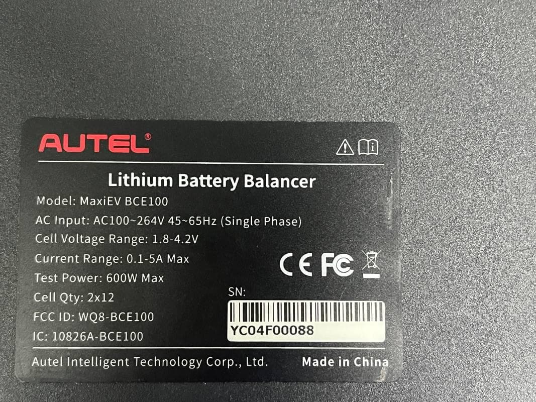
WQ8-BCE100
Jun 26, 2024LITHIUM BATTERY BALANCER
Equipment Class
DTS - Digital Transmission System
WQ8-ALT100L
Apr 01, 2024Battery Leakage Tester
Equipment Class
DTS - Digital Transmission System
WQ8-SK2311
Feb 19, 2024UNIVERSAL SMART KEY
Equipment Class
DSC - Part 15 Security/Remote Control TransmitterWQ8-DA2211
Jan 23, 2024ADAS Calibration Frame
Equipment Class
DSS - Part 15 Spread Spectrum Transmitter