WSJV6AVIATION VHF AM TRANSCEIVER
Rainbow Aircraft, Inc.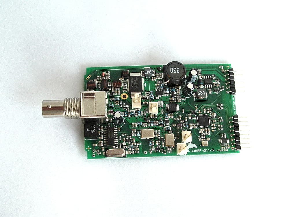
Click to zoom
Application Details
- Equipment Class
- TNB - Licensed Non-Broadcast Station Transmitter
- Date of Grant
- Oct 06, 2011
- Application Purpose
- Original Equipment
- Date of Application
- Oct 06, 2011
- Equipment Note
- AVIATION VHF AM TRANSCEIVER
- Frequency Range
- 118.00000000 - 136.97500000
- Company
- Rainbow Aircraft, Inc.
- Country
- United States
Documents & Files
Document Text
Text extracted from the exhibit documents filed with the FCC. Open a document above to read the original.
Users Manual
MGL Avionics VHF Airband Transceiver Model V6 User & Installation Manual PRELIMINARY - 9/2011 General Please read this manual before operating the V6 Transceiver Please include this manual if ownership of the V6 Transceiver changes Operational limitations, conditions and restrictions Do not operate this unit outside of its specified temperature range – this may result in malfunction or damage to the unit. Observe the installation wiring diagrams. Incorrect wiring may damage this unit. Never operate this unit outside of its specified voltage range. Doing so may cause serious damage to this unit. At all times ensure that no reverse polarity power is applied to this unit. Reverse polarity will destroy this unit . This Transceiver is designed to withstand the possible power surges that may occur in a correctly wired power supply system of a typical aircraft. For this reason the Transceiver may be left switched on when engines are started. Please note that the supply voltage may drop below minimum operating voltage during engine cranking. During this time operation of the radio will not be possible. Do not operate the transmitter of this unit without connecting a correctly adjusted antenna. Doing so may result in damage to the unit. The V6 Transceiver is not FAA type certified. This unit may only be used in aircraft where such a unit is permitted under local rules. Typically these rules permit operation in non-type certified aircraft such as home built and experimental or sport category aircraft. Limitations may exist on maximum altitudes above which a non-certified airband Transceiver may not be operated. Please check local rules with the relevant authorities. Use of this radio may be subject to a radio station license. Please contact the local radio frequency spectrum governing body (such as the FCC) to inquire as to the procedures required to obtain a radio station license. Operation of this Transceiver may only be allowed by persons holding a valid radio license (restricted or full). Please do not operate this Transceiver illegally. Please do not operate this Transceiver in an environment or in conditions where its transmissions may cause interference to other electronic equipment or systems. Never operate an airband radio without the required qualifications to do so. Never cause a nuisance to aircraft on the ground or in the air by misuse of this Transceiver in any way. Never compromise the safety of other aircraft with lengthy transmissions. Keep transmissions short and to the point following established air to air and air to ground rules and procedures. 2 Table of Contents General.................................................................................................................2 Operational limitations, conditions and restrictions...........................................2 The V6 Panel........................................................................................................4 The V6 controls.....................................................................................................5 The “VOL/SQ” control.......................................................................................5 The “ACTIVE” button........................................................................................6 The “FREQUENCY” control..............................................................................6 Setting frequencies.......................................................................................7 Changing channels.......................................................................................7 RX/TX bargraph...........................................................................................8 The 'MENU” button...........................................................................................9 Menu structure.............................................................................................9 First level menu...............................................................................................11 Ambient noise suppression.........................................................................11 Program channels......................................................................................12 Contrast......................................................................................................12 Microphone level........................................................................................13 Microphone bandpass filter........................................................................13 PTT Mode...................................................................................................14 Auxiliary input level.....................................................................................14 Scanning state at power up........................................................................14 Setup .........................................................................................................14 Second level menu.........................................................................................15 TX MIC VOX / TX MIC HOT.......................................................................15 TX LOCK ON / TX LOCK OFF...................................................................15 P-scan ON / P-scan OFF............................................................................15 Direct FS / Flip-Flop FS..............................................................................16 1 MIC Level / 4 MIC Level..........................................................................16 CHANNEL spacing.....................................................................................16 Default........................................................................................................16 Installation...........................................................................................................17 General installation notes .............…
Text truncated - open the document above for the full version.
Internal Photos
DS Board ____________________________________________________________________________________________________________________________________________________________________________ Page 21 of 24 Test Report No 110809.1 19 th September 2011 This report may not be reproduced except in full. Internal Photographs Front View LCD Panel Front cover Front PCB connections ____________________________________________________________________________________________________________________________________________________________________________ Page 22 of 24 Test Report No 110809.1 19 th September 2011 This report may not be reproduced except in full. Main PCB – Control Main PCB – RF PCB Rear View RF connector and D25 connector IO Board RF Boards Rotary control board
RF Exposure Info
____________________________________________________________________________________________________________________________________________________________________________ Page 18 of 24 Test Report No 110809.1 19 th September 2011 This report may not be reproduced except in full. Radio Frequency Hazard Information As per Section 1.1310 mobile transmitters are required to be operated in a manner that ensures that the public is not exposed to RF energy levels in accordance with OST/OET Bulletin Number 65. A minimum safe distance between the user / general public and the device has been calculated below. In accordance with Section 1.1310 the Maximum Permissible Exposure (MPE) power density limit for the General Population / Uncontrolled Exposure of 0.2 mW/m2 or 27.5 V/m has been applied. The minimum distance from the antenna at which the MPE is met is calculated from the equation relating field strength in V/m, transmit power in watts, transmit antenna gain and separation distance in metres: The rated power of this transmitter is 6.5 watts which has been measured to be 5.9 watts when powered at 13.8 Vdc. In a typically mobile installation this transceiver would be used with a whip ¼ wave dipole type of antenna with a gain of 1.64. d = (30 * P * G) / E = (30 * 6.5 * 1.64 ) / 27.5 = 0.65 metres or 65 cm The above calculations show that this device will meet the MPE requirement for mobile devices providing a safe distance of at least 65 cm is provided. A warning to this affect will need to be inserted in the equipment manual. Result: Complies
Test Report
____________________________________________________________________________________________________________________________________________________________________________ Page 1 of 24 Test Report No 110809.1 19 th September 2011 This report may not be reproduced except in full. EMC Technologies (NZ) Ltd PO Box 68-307 Newton, Auckland Phone 09 360 0862 Fax 09 360 0861 E-Mail Address: [email protected] Web Site: www.emctech.com.au TEST REPORT MGL Avionics V6 VHF Air Band Transceiver tested for compliance with the Code of Federal Regulations (CFR) 47 Part 87 –Aviation Services Part 15 – Radio Frequency Devices for MGL Avionics cc This Test Report is issued with the authority of: ______________________________________ Andrew Cutler - General Manager ____________________________________________________________________________________________________________________________________________________________________________ Page 2 of 24 Test Report No 110809.1 19 th September 2011 This report may not be reproduced except in full. Table of Contents 1. CLIENT INFORMATION 3 2. DESCRIPTION OF TEST SAMPLE 3 3. COMPLIANCE STATEMENT & RESULT SUMMARY 4 4. TEST SAMPLE DESCRIPTION 5 5. TEST CONDITIONS 6 6. ATTESTATION 7 7. TEST RESULTS 8 8. TEST EQUIPMENT USED 19 9. ACCREDITATIONS 19 10. PHOTOGRAPH (S) 20 ____________________________________________________________________________________________________________________________________________________________________________ Page 3 of 24 Test Report No 110809.1 19 th September 2011 This report may not be reproduced except in full. 1. CLIENT INFORMATION Company Name MGL Avionics cc Address 5 Fuchsia Street Somerset West 7130 Country South Africa Contact Mr Rainer Lamers 2. DESCRIPTION OF TEST SAMPLE Brand Name MGL Avionics Model Tested V6 Product VHF Aircraft Transceiver Manufacturer MGL Avionics Country of Origin South Africa Serial Number V6 110700103 FCC ID WSJV6 ____________________________________________________________________________________________________________________________________________________________________________ Page 4 of 24 Test Report No 110809.1 19 th September 2011 This report may not be reproduced except in full. 3. COMPLIANCE STATEMENT & RESULT SUMMARY The MGL Avionics V10 VHF Airband Transceiver complies with 47 CFR Part 87 and Part 15 when tested in accordance with 47 CFR Part 2, Part 15 and Part 87 when the test methods as described in ANSI C63.4 – 2003 were applied. A summary of the applicable clauses is detailed below Clause Test Performed Result 2.1041 Measurement procedures Noted 2.1057 Frequency spectrum to be investigated Noted 87.131 Power and emissions Complies 2.1046 RF power output Noted 87.133 Frequency stability Complies 2.1055 Frequency stability Noted 87.135 Bandwidth of emission Complies 2.202 Bandwidths Noted 87.137 Types of emissions Complies 87.139 Emission limitations Complies 2.1049 Occupied bandwidth Noted 2.1051 Spurious emissions at antenna terminals Complies 2.1053 Field strength of spurious radiation Complies 87.141 Modulation requirements Complies 2.1047 Modulation Characteristics Noted 2.1047(a) Low pass filter response Complies 2.1047(b) Modulation limiting characteristics Complies 15.111 Antenna conducted power measurement Complies 1.1310 Radio frequency radiation exposure limits Complies ____________________________________________________________________________________________________________________________________________________________________________ Page 5 of 24 Test Report No 110809.1 19 th September 2011 This report may not be reproduced except in full. 4. TEST SAMPLE DESCRIPTION The sample tested has the following specifications: Rated Transmitter Output Power 6.5 watts (38.1 dBm) at 13.8 Vdc 5.0 watts (37.0 dBm) at 12.0 Vdc 3.5 watts (35.4 dBm) at 10.0 Vdc Transmitter frequency range 118.0000 – 136.9750 MHz Receiver frequency range 108.0000 – 136.9750 MHz Test frequency 127.0000 MHz Channel spacing 25.0 kHz The transceiver is capable of tuning in steps of 1 MHz, 50 kHz or 25 kHz. FCC Bands Part 87: 118.000 – 137.000 MHz Emission Designators / Modes of operation 6K00A3E Power Supply External supply between 10 – 28 Vdc supply. Typical operating voltage would be 13.8 Vdc ____________________________________________________________________________________________________________________________________________________________________________ Page 6 of 24 Test Report No 110809.1 19 th September 2011 This report may not be reproduced except in full. 5. TEST CONDITIONS Standard Temperature and Humidity Temperature: +25C 4 maintained. Relative Humidity: 60% 10% observed. Standard Test Power Source Standard Test Voltage: 13.8 Vdc. Extreme Temperature High Temperature: + 50C maintained. Low Temperature: - 20 C maintained. Extreme Test Voltages High Voltage: 28.0 Vdc Low Voltage: 10.0 Vdc Testing carried out at the extremes of voltages as stated by customer ____________________________________________________________________________________________________________________________________________________________________________ Page 7 of 24 Test Report No 110809.1 19 th September 2011 This report may not be reproduced except in full. 6. AT T E S TAT I O N Testing of the MGL Avionics V10 VHF Aircraft Transceiver complies with the Code of Federal Regulations (CFR) 47 Part 87 – Aviation Services and (CFR) 47 Part 15 – Radio Frequency Devices. This report describes the tests and measurements performed for the purpose of determining compliance with the specification with the following conditions: The client selected the test sample. The report relates only to the sample tested. This report does not contain corrections or erasures. Measurement uncertainties with statistical confidence intervals of 95% are shown below test results. Both Class A and Class B uncertainties have been accounted for, as well as influence uncertainties where appropriate. In addition this equipment has been tested i…
Text truncated - open the document above for the full version.
Test Setup Photos
____________________________________________________________________________________________________________________________________________________________________________ Page 23 of 24 Test Report No 110809.1 19 th September 2011 This report may not be reproduced except in full. Open Air Test Site Photographs ____________________________________________________________________________________________________________________________________________________________________________ Page 24 of 24 Test Report No 110809.1 19 th September 2011 This report may not be reproduced except in full.
Contact Information
Applicant
Matt Liknaitzky
Test Firm
EMC Technologies NZ Ltd.Andrew Cutler
Technical Specifications
| # | Rule Parts | Frequency Range | Power Output | Emission | Tolerance |
|---|---|---|---|---|---|
| 1 | 87 | 118 MHz - 136.975 MHz | 6.5 W | 6K00A3E | 20.0000000000 ppm |