WU2SMRSFQIIDigital Radio Slave
SMDV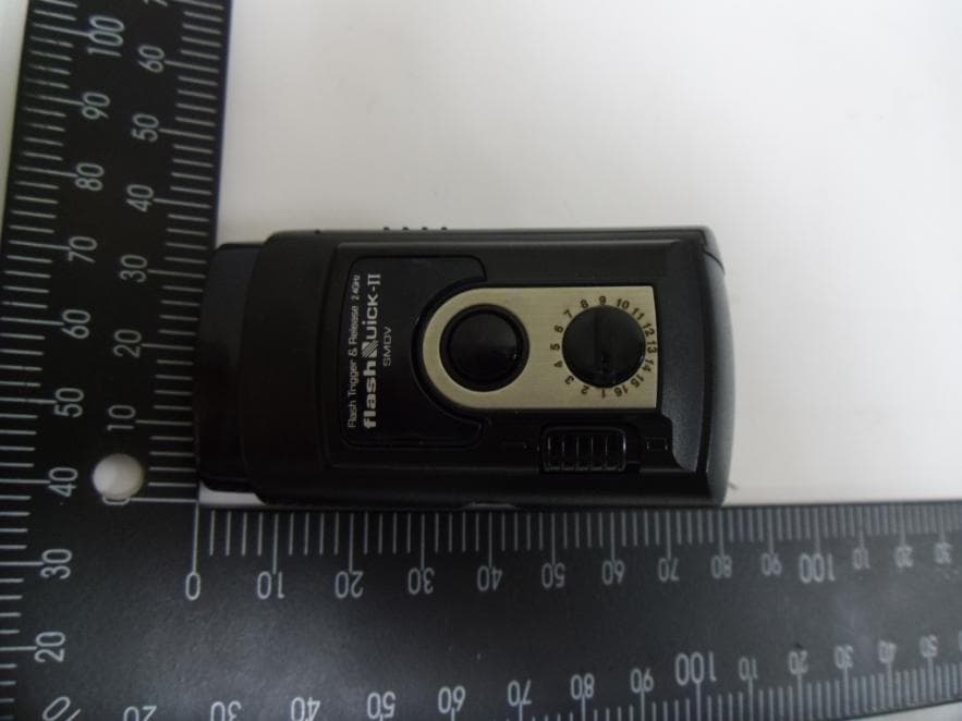
Click to zoom
Application Details
- Equipment Class
- DXX - Part 15 Low Power Communication Device Transmitter
- Date of Grant
- Aug 12, 2012
- Application Purpose
- Original Equipment
- Date of Application
- Aug 12, 2012
- Equipment Note
- Digital Radio Slave
- Frequency Range
- 2427.00000000 - 2457.00000000
- Company
- SMDV
- Country
- South Korea
Documents & Files
Document Text
Text extracted from the exhibit documents filed with the FCC. Open a document above to read the original.
Users Manual
FlashQuick-II User’s Guide I. SET UP AND OPERATIONS A. To Trigger Flash or Strobe 1. Insert the transmitter into the hot shoe of your camera. If your camera doesn’t have a hot shoe, use the included 2.5mm to PC cable to connect the transmitter to your camera equipped with a PC sync flash terminal. 2. Select the operating channel. 3. Switch on the power of the transmitter. 4. Install two AAA batteries into the receiver (observe the polarity of the batteries as indicated). 5. Ensure your flash lights are turned off. 6. For portable flash unit, mount the portable flash directly on the receiver’s hot shoe. For strobes, connect the receiver with an appropriate cable and adapter. (A cable with 3.5mm mono plug and 6.3mm plug adapter are included.) 7. Ensure the channel on the receiver matches that of the transmitter. 8. Switch on the power of the receiver. B. Changing Channels FlashQuick-II has 16 channels. To operate, the transmitter and receiver must be on the same channel. To change the channel, follow these steps: 1. Turn off the transmitter and the receiver. 2. Select the desired channel on the transmitter and the receiver 3. Turn on the transmitter and the receiver. C. To Trigger a Remote Camera FlashQuick-II can be used to trigger a remote camera. Your camera must be equipped with an electronic shutter release input. An additional accessory cable (not included) may be required. The camera you use determines the cable that you need. With the proper cable, follow these easy steps: 1. Locate the electronic shutter release input on your camera. 2. Connect FlashQuick-II receiver to the camera’s electronic shutter release input using the appropriate accessory cable. 3. Ensure the transmitter and the receiver are set to the same channel. 4. Power on both the transmitter and receiver. 5. Press TEST button on the transmitter unit to operate auto focus function and shutter function of the remote camera. PLEASE NOTE: A single FlashQuick-II transmitter cannot trigger both the remote camera and flash/strobe units. To remotely trigger a camera and trigger flash to sync with the camera, two transmitter units operating on two different channels are required. Because cameras have shutter lag (delay inside a camera), when the receivers on the camera and flash are operating on the same channel, even if the signal from the single transmitter reaches the receivers at the same time, flash will normally fire before the shutter is released. Therefore, to remotely trigger a camera and flash, set the transmitter and receiver triggering the camera to channel X and set the transmitter and receiver triggering the flash to channel Y. FCC Compliance This device complies with Part 15 of the FCC Rules. Operation is subject to the conditions that this device does not cause harmful interference, and accepts any interference received, even if it causes undesired operation. Any changes or modifications (including the antennas) made to this device that are not expressly approved by the manufacturer may void the user’s authority to operate the equipment.
Cover Letter(s)
부산시 사상구 낙동대로1532 (삼락동), 617-825 #53-42, Nakdongdae-ro, Sasang-gu, Busan, 617-825, Korea Tel Tel. 82-51-324-0788Fax : 82-51-301-0788Website : www.smdv.co.kr Date: June. 22, 2012 Federal Communications Commission 7435 Oakland Mills Road Columbia MD 21046 c.c. Compliance Certification Services Certification Division 47173 Benicia Street Fremont, CA 94538, USA To whom it may concern: I, the undersigned, hereby authorize Lab Manager Charles. Kim (or Feel. Jeong) of SGS Korea Co., Ltdand hereafter referred to as SGS Korea, to act on our behalf in all manners relating to application for equipment authorization, including signing of all documents relating to these matters. Any and all acts carried out by Lab Manager Charles. Kim (or Feel. Jeong) of SGS Korea Co., Ltdon our behalf shall have the same effect as acts of our own. I, the undersigned, hereby certify that we are not subject to a denial of federal benefits, that includes FCC benefits, pursuant to Section 5301 of the Anti-Drug Abuse Act of 1988, 21 U.S.C. 853(a). In authorizing SGS Korea as our agent, we still recognize that we are responsible to: a)comply with the relevant provisions of the certification program; b)make all necessary arrangements for the conduct of the evaluation, including provision for examining documentation and access to all areas, records (including internal audit reports) and personnel for the purposes of evaluation (e.g. testing, inspection, assessment, surveillance, reassessment) and resolution of complaints; c)make claims regarding certification only in respect of the scope for which certification has been granted; d)do not use our product certification in such a manner as to bring the Certification Division into disrepute andnot make any statement regarding our product certification which the Certification Division may consider misleading or unauthorized; e)upon suspension or cancellation of certification, discontinue use of all advertising matter that contains any reference thereto and return any certification documents as required by the Certification Division; f)use certification only to indicate the products are certified as being in conformity with specified standards; g)endeavor to ensure that no certificate or report nor any part thereof is used in a misleading manner; h)ensure that any reference to our product certification in communication media such as documents, brochures or advertising, complies with the requirements of the Certification Division; i)keep a record of all complaints made known to the us relating to the product’s compliance with requirements of the relevant standard and to make these records available to the Certification Division when requested; j)take appropriate action with respect to such complaints and any deficiencies found in products or services that affect compliance with the requirements for certification; k)document the actions taken. This authorization is valid until further written notice from the applicant. Sincerely Yours, Jong-Seok Kim / President
External Photos
Model : Flashquick-II External photos of EUT Model : Flashquick-II Top view of EUT Bottom view of EUT Model : Flashquick-II Top view of EUT Bottom view of EUT Model : Flashquick-II Side view of EUT
ID Label/Location Info
FCC Label 1. FCC Label Drawing SMDV Model : FlashQuick-II FCC ID : WU2SMRSFQII Made in Korea 2. FCC Label Location Bottom side of EUT FCC Label 1. FCC Label Drawing SMDV Model : FLASHPOINT FCC ID : WU2SMRSFQII Made in Korea 2. FCC Label Location Bottom side of EUT FCC Label 1. FCC Label Drawing SMDV Model : Freq Sync Transmitter FCC ID : WU2SMRSFQII Made in Korea 2. FCC Label Location Bottom side of EUT
Internal Photos
Model : Flashquick-II Internal photos of EUT Model : Flashquick-II Top view of Main board Bottom view of Main board Model : Flashquick-II Micro strip(PCB) Antenna Antenna aa
Test Report
Report Number: F690501/RF-RTL005633-2 Page: 2 of 15 The results shown in this test report refer only to the sample(s) tested unless otherwise stated. This test report cannot be reproduced, except in full, without prior written permission of the Company. SGS Testing Korea Co., Ltd. 8-34, Sanbon-dong, Gunpo-si, Gyeonggi-do, Korea, 435-040 Tel. +82 31 428 5700 / Fax. +82 31 427 2371 www.electrolab.kr.sgs.com INDEX Table of Contents Page 1. General information -------------------------------------------------------------------------------- 3 2. Fundamental, Spurious emission and edge band radiated emission ----------------- 6 3. Bandwidth of operation frequency--------------------------------------------------------------- 12 Report Number: F690501/RF-RTL005633-2 Page: 3 of 15 The results shown in this test report refer only to the sample(s) tested unless otherwise stated. This test report cannot be reproduced, except in full, without prior written permission of the Company. SGS Testing Korea Co., Ltd. 8-34, Sanbon-dong, Gunpo-si, Gyeonggi-do, Korea, 435-040 Tel. +82 31 428 5700 / Fax. +82 31 427 2371 www.electrolab.kr.sgs.com 1. General information 1.1 Testing laboratory SGS Korea Co., Ltd. (Gunpo Laboratory) - 413-15, Gomae-Dong Giheung-Gu, Yongin-Si, Gyeonggi-Do, South Korea. - Wireless Div. 3FL, 18-34, Sanbon-dong, Gunpo-si, Gyeonggi-do, Korea 435-040 www.ee.sgs.com/korea Telephone : +82 31 428 5700 FAX : +82 31 427 2371 1.2 Details of applicant Applicant : SMDV Address : 280-11, MORA-1, SASNG-GU, BUSAN, Korea Contact Person : Ji Young, Kim Phone No. : +82 051 324 0788 1.3. Description of EUT Kind of Product Digital Radio Slave Model Name FlashQuick-II Serial Number N/A Power Supply DC 1.5 V Frequency Range 2427 ㎒ ~ 2457 ㎒ Modulation Technique GFSK Number of Channels 16 Antenna Type Micro strip(PCB) Antenna 1.4 Details of modification -N/A Report Number: F690501/RF-RTL005633-2 Page: 4 of 15 The results shown in this test report refer only to the sample(s) tested unless otherwise stated. This test report cannot be reproduced, except in full, without prior written permission of the Company. SGS Testing Korea Co., Ltd. 8-34, Sanbon-dong, Gunpo-si, Gyeonggi-do, Korea, 435-040 Tel. +82 31 428 5700 / Fax. +82 31 427 2371 www.electrolab.kr.sgs.com 1.5. Test equipment list Equipment Manufacturer Model S/N Cal Date Cal Interval Cal Due. Signal Generator R&S SMJ 100A 100882 Nov. 25, 2011 Annual Nov. 25, 2012 Spectrum Analyzer R&S FSV30 101004 Jul. 06, 2011 Annual Jul. 06, 2012 High Pass Filter Wainwright WHK3.0/18G-10SS344 Jul. 05, 2011 Annual Jul. 05, 2012 Low Pass Filter Mini circuits NLP-1200+ V9500401023-1 Aug. 22, 2011 Annual Aug. 22, 2012 DC Power Supply Agilent U8002A MY50020026Mar. 29, 2012 Annual Mar. 29, 2013 Preamplifier R & S 8447D 1726A01265Sep. 28, 2011 Annual Sep. 28, 2012 Preamplifier R & S SCU 18 10070 Aug. 10, 2011 Annual Aug. 10, 2012 Preamplifier MITEQ Inc. JS44-18004000-35-8P1546891 Jul. 04, 2012 Annual Jul. 04, 2013 Test Receiver R & S ESU40 100075 Feb. 13, 2012 Annual Feb. 13, 2013 Bilog Antenna SCHWARZBECK VULB9163 9163-437 Aug. 03, 2011 Biennial Aug. 03, 2012 Horn Antenna R&S HF906 100326 Nov. 23, 2010 Biennial Nov. 23, 2012 Horn Antenna SCHWARZBECK MESSELEKTRONIK BBHA9170 BBHA9170431May 15, 2012 Biennial May 15, 2014 Antenna Master INN-CO MA4000-EP N/A N.C.R N/A N.C.R. Turn Table INN-CO DT-3000S N/A N.C.R N/A N.C.R. Anechoic Chamber SY Corporation L × W × H (21.5 m × 13.0 m × 9.0 m) N/A N.C.R N/A N.C.R. 1.6. Support equipment Equipment Manufacturer Model name S/N - - - - Report Number: F690501/RF-RTL005633-2 Page: 5 of 15 The results shown in this test report refer only to the sample(s) tested unless otherwise stated. This test report cannot be reproduced, except in full, without prior written permission of the Company. SGS Testing Korea Co., Ltd. 8-34, Sanbon-dong, Gunpo-si, Gyeonggi-do, Korea, 435-040 Tel. +82 31 428 5700 / Fax. +82 31 427 2371 www.electrolab.kr.sgs.com 1.6. Summary of test results The EUT has been tested according to the following specifications: Applied Standard : FCC Part15, Subpart C Standard Section Test Item Result 15.209(a) 15.249(a) 15.249(d) 15.205 Fundamental, Spurious emission and edge band radiated emission Complied 1.7. Test report revision Revision Report number Description 0 F690501/RF-RTL005633 Initial 1 F690501/RF-RTL005633-1 update the Horn antenna in Test equipment list 2 F690501/RF-RTL005633-2 List the average limit Report Number: F690501/RF-RTL005633-2 Page: 6 of 15 The results shown in this test report refer only to the sample(s) tested unless otherwise stated. This test report cannot be reproduced, except in full, without prior written permission of the Company. SGS Testing Korea Co., Ltd. 8-34, Sanbon-dong, Gunpo-si, Gyeonggi-do, Korea, 435-040 Tel. +82 31 428 5700 / Fax. +82 31 427 2371 www.electrolab.kr.sgs.com 2. Fundamental, Spurious emission and edge band radiated emission 2.1. Test setup The diagram below shows the test setup that is utilized to make the measurements for emission from 30 ㎒ to 1 ㎓ Emissions. The diagram below shows the test setup that is utilized to make the measurements for emission .The spurious emissions were investigated form 1 ㎓ to the 10th harmonic of the highest fundamental frequency or 40 ㎓, whichever is lower. Report Number: F690501/RF-RTL005633-2 Page: 7 of 15 The results shown in this test report refer only to the sample(s) tested unless otherwise stated. This test report cannot be reproduced, except in full, without prior written permission of the Company. SGS Testing Korea Co., Ltd. 8-34, Sanbon-dong, Gunpo-si, Gyeonggi-do, Korea, 435-040 Tel. +82 31 428 5700 / Fax. +82 31 427 2371 www.electrolab.kr.sgs.com 2.2. Test procedures Radiated emissions from the EUT were measured according to the dictates of ANSI C63.4:2003 1. The EUT was placed on the top of a rotating table 0.8 meters above the ground at a 3 meter anechoic Chamber. The table was rotated 360 degrees to determine the position of the hi…
Text truncated - open the document above for the full version.
Test Setup Photos
Test setup photos of EUT A. Photo of Field Strength & Spurious Emission Test
Contact Information
Applicant
Jong Seok Kim(President)
Test Firm
SGS Korea Co., Ltd.Forest Lee
Technical Specifications
| # | Rule Parts | Frequency Range | Power Output |
|---|---|---|---|
| 1 | 15C | 2.43 GHz - 2.46 GHz | - |
Other Applications from SMDV
WU2SMRSRFN4
Aug 12, 2012Digital Radio Slave
Equipment Class
DXX - Part 15 Low Power Communication Device Transmitter
WU2SMRS0911
Mar 09, 2010Digital Radio Slave
Equipment Class
DXX - Part 15 Low Power Communication Device Transmitter