WU9ET-DC012.4GHz WIRELESS H.264 DIGITAL CAMERA
E-TECS LIMITED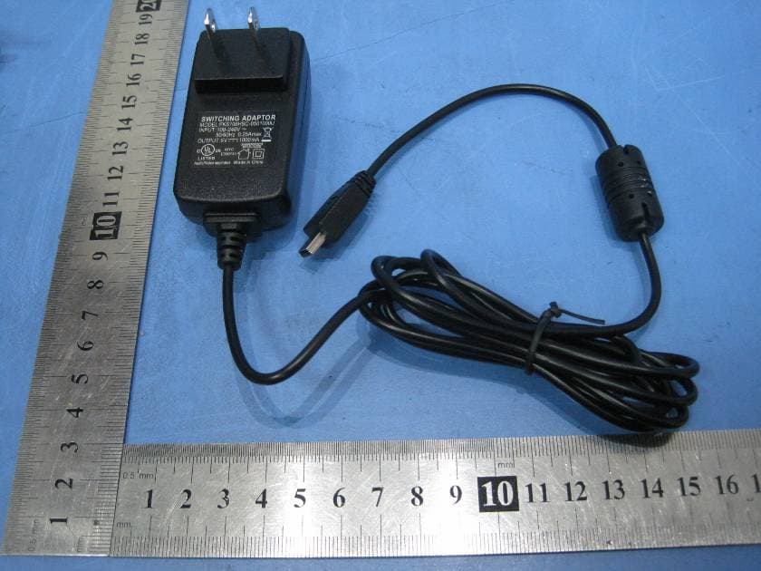
Click to zoom
Application Details
- Equipment Class
- DSS - Part 15 Spread Spectrum Transmitter
- Date of Grant
- Sep 14, 2011
- Application Purpose
- Original Equipment
- Date of Application
- Sep 14, 2011
- Equipment Note
- 2.4GHz WIRELESS H.264 DIGITAL CAMERA
- Frequency Range
- 2414.25000000 - 2461.50000000
- Company
- E-TECS LIMITED
- Country
- China
Documents & Files
Document Text
Text extracted from the exhibit documents filed with the FCC. Open a document above to read the original.
Users Manual
2.4GHZ WIRELESS H.264 DIGITAL CAMERA USER MANUAL FCC Notice to Users This equipment has been tested and found to comply with the limits for a Class B digital device, pursuant to Part 15 of the FCC Rules. These limits are designed to provide reasonable protection against harmful interference in a residential installation. This equipment generates, uses and can radiate radio frequency energy and, if not installed and used in accordance with the instructions, may cause harmful interference to radio communications. However, there is no guarantee that interference will not occur in a particular installation. If this equipment does cause harmful interference to radio or television reception, which can be determined by turning the equipment off and on, the user is encouraged to try to correct the interference by one or more of the following measures: -- Reorient or relocate the receiving antenna -- Increase the separation between the equipment and receiver. -- Connect the equipment into an outlet on a circuit different from that to which the receiver is connected. -- Consult the dealer or an experienced radio/TV technician for help. This device complies with Part 15 of the FCC Rules. Operation is subject to the following two conditions: (1) this device may not cause harmful interference, and (2) this device must accept any interference received, including interference that may cause undesired operation. The manufacturer is not responsible for any radio or TV interference caused by unauthorized modifications to this equipment. Such modifications could void the user's authority to operate the equipment. The antenna used for this transmitter must be installed to provide a separation distance of at least 20 cm from all persons and must not be co-located or operated in conjunction with any other antenna or transmitter 01 02 8 CAMERA ① Only for firmware upgrade ② Camera Lens ③ RESET button ④ Mini USB connection ⑤ On/Off/PAIR button ⑥ Power and charging status indicator LED ⑦ Microphone ⑧ Mount hole NOTE:ON/OFF: Press and hold button for 3 to 5seconds. PAIR:Press and quickly release button. 1.NIGHT-VISION(IR)OPERATION: The camera is equipped with eight(8) Infrared LEDS for night- vision operation. In low light situation the Infrared LEDS turn-on automatically, to activate night-vision. NOTE: The night-vision picture is always black & white and not that sharp. This camera has up to 10 feet night-vision range. 2. USING CAMERA STAND/MOUNT ● Screw the camera the /mount and as shown or to a wall or ceiling(screws no included). onstandsetup screwit 3. CHARGING RECHARGEABLE BATTERY IN TRANSMITTER (CAMERA) The rechargeable battery supplied with the transmitter (camera) must be fully charged before it is used for the first time on battery power. Warning: Only qualified technicians or our technical staff is authorized to change the rechargeable battery in the transmitter! NOTE:The transmitter automatically turns on and the battery starts getting charged when AC adapter or a USB cable connected to a computer is plugged into the MINI USB socket . ● When the transmitter is turned o , the flashes , s. When the transmitter is turned o s. ● The charging time for a fully rechargeable battery when the device is turned off is approximately 5 hours. The charging time double if the transmitter is turned on whil the battery is ing charged. on the transmitter nand the battery is getting chargedpower status LEDgreenand once the battery is fully charged the LED become solid ffand the battery is getting charged the power status LEDflashes redand once the battery is fully charged the LEDturn off discharged segett 03 4. USING THE TRANSMITTER(CAMERA) ● For optimal transmission, place the camera in the room to be monitored in such a way as to ensure the optimal surveillance of your baby or the elderly. You can also mount the camera using the stand included as described in section 2 . Note:For safety reasons and for optimum sound transmission we recommend that you keep the transmitter at least 1 meter(3 feet) from the baby. IMPORTANT:Never place camera in the baby's cot, bed or playpen! NOTE:The transmitter will automatically turn on when plugged into AC adapter or computer. ● The transmitter can be powered with the , the rech- argeable battery, or via computer USB cable. ● To use the rechargeable battery, the device shall be turned on without the plugged in. ● The transmitter turns on when the ON/OFF/PAIR button is pressed for 5 seconds. As soon as the camera is powered on the LED indicator flash green to . ,ress ON/OFF/PAIR button for 5 seconds. ● When the battery voltage falls below 3.6V the Power Indicator LED turns red from green,indicating the battery needs to be charged. The receiver displays "Camera battery is low"on the screen. IMPORTANT: . (hardware to mount the stand toawall orceilingnot included) AC adapter 's USB port using a AC adapter turns solid green oresindicate the camera is powered on Toturncameraoffp In case of audio or video interference press and release RESET button to switch transmitter to a different channel 04 5.REGISTER/PAIR CAMERA FOR WITH 2.4" SCREEN BABY MONITOR: ● Turn camera power ON ● Turn Monitor ON Menu/OK → Main Menu → Multi Camera → Register Camera → Camera 1 → Register Camera 1? → Yes n transmitter/camera → On/Off Note:Press and quickly release the ON/OFF/PAIR button on the CAMERA to complete pairing process. ● Press"OK/MENU"button on the monitor to display Main Menu. ● Use "UP"or "DOWN"button to highlight "Multi Camera" Option and press "OK/MENU" button to complete the selection. ● From "Multi Camera" Menu highlight "Register Camera" using "UP" or "DOWN" button and press "OK/MENU"button to complete the selection ● From "Register Camera" Menu highlight one of the available(not used) camera number you want to assign to this new camera and press "OK/MENU" button to complete the selection. NOTE:Camera numbers which have already been allocated (used to register existing cameras) have "thumbs up" s…
Text truncated - open the document above for the full version.
Block Diagram
HP3129 24Mhz Crystal 32k RTC keypad SPI flashSDRAM Battery charger usb port Power manegment LEDs indicator 2.4g RF module 1.2v2.8v3.3v Battery UART Antenna Camera mic A7121 2.4G Transceiver PA Switch To CPU 2.4G RF Module SAW 18Mhz Crystal LNA
Cover Letter(s)
E-TECS LIMITED FCC ID: WU9ET-DC01 POWER OF ATTORNEY August 4, 2011 Federal Communications Commission Authorization and Evaluation Division 7435 Oakland Mills Road Columbia, MD 21046 To Whom It May Concern: We, the undersigned, hereby authorize Waltek Services (ShenZhen) Co., Ltd. (Philo Zhong) on our behalf, to apply to the Federal Communications Commission on our equipment. Any and all acts carried out by Waltek Services (ShenZhen) Co., Ltd. (Philo Zhong) on our behalf shall have the same effect as acts of our own. This authorization expires on August 3, 2012. This is to advise that we are in full compliance with the Anti-Drug Abuse Act. We, E-TECS LIMITED, are not subject to a denial of federal benefits pursuant to Section 5301 of the Anti-Drug Act of 1988, 21 USC853a, and no party to the application is subject to a denial of federal benefits pursuant to that section. Sincerely, E-TECS LIMITED ----------------------- Duncan DU (Senior Manager)
External Photos
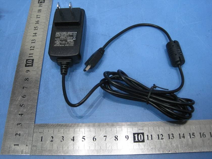
2.1 EUT - Front View 2.2 EUT - Back View 2.3 Adapter - Front View 2.4 Adapter - Back View
ID Label/Location Info
E-TECS LIMITED FCC ID: WU9ET-DC01 Ref. No.: WT11031367-S-E-F Page 56 of 56 18 FCC ID Label This device complies with Part 15 of the FCC Rules. Operation is subject to the following two conditions:(1)this device may not cause harmful interference,and (2) this device must accept any interference received, including interference that may cause undesired operation. The Label must not be a stick-on paper. The Label on these products must be permanently affixed to the product and readily visible at the time of purchase and must last the expected lifetime of the equipment not be readily detachable. Proposed Label Location on EUT EUT Bottom View/proposed FCC Mark Location FCC ID: WU9ET-DC01 This device com plies with Part 15 of the FCC Rules. Operation is subject to the following two conditions:(1)this device ma y not cause harmful interference,and (2) this device must accept any interference received, including interference that may cause undesired operation.
ID Label/Location Info
FCC ID Label Sample for Model: ET-DC01 FCC ID: WU9ET-DC01 This device complies with Part 15 of the FCC Rules. Operation is subject to the following two conditions:(1)this device may not cause harmful interference,and (2) this device must accept any interference received, including interference that may cause undesired operation.
Internal Photos
2.1 EUT - Open View 2.2 PCB 1 - Front View 2.3 PCB 1 - Back View 2.4 PCB - Module Open View 2.5 PCB 2 - Front View 2.6 PCB 2 - Back View 2.7 PCB(Adapter) - Front View 2.8 PCB(Adapter) - Back View
Operational Description
ET-DC01 Circuit Description This product is a TRANSCEIVER. When press “on/off” button of the product, the power system will work, all the circuit will be supplied by this power system. And the main chip HPC3129,which the OSC is 24Mhz and 32.768khz, will run the code by this OSC, then it turn on the necessary circuit. include the RF module and camera. In this time, Processor works first to build up communication chain for another TRANSCEIVER. When the wirdless chain setuped successfully, it will capture the moving pictures through camera and encoding it to H.264 format, then it can put the datastream to the RF module, Another TRANSCEIVER will receive the data from RF module, and display them on the LCD.
Schematics
LDO/300ma connect TransceiverSwitch & RFPA 1 MARK1 NC-FIDUCIALMARK 1 MARK2 NC-FIDUCIALMARK 1 BP_LIM2 2 BP_LIM1 3 BP_BPF 4 VDD_A 5 RFI 6 RFO 7 VDD_VCO 8 BP_VCO 9 VT 10 CPO 11 VDD_PLL 12 XI 13 XS 14 FP_RDY 15 BB_CLK 16 MS1 17 MS0 18 RESETN 19 F_CLK 20 TXD 21 TRXD 22 CD_TXEN 23 RX_SYN 24 RX_CLK 25 VDD_D 26 SPI_RXD 27 SPI_TXD 28 SPI_CLK 29 SPI_CS 30 BP_LPF 31 BP_DS 32 RSSI 33 GND U3 RF-TRANSCEIVER_A7121 1 2 3 4 5 6 7 8 9 10 11 12 13 14 15 16 17 18 19 20 J1 NC-PAD-20PIN 1 2 U4 CRASTAL-18MHZ 1 VDD 2 GND 3 CE 5 VOUT 4 NC U601 LDO-2.8V-R1114N281D C1 1uF C2 0.1uF C3 0.1uF C4 0.1uF C5 1000PF C6 20PF C7 120pF R1 39K C8 0.1uF C9 10PF C10 56pF R2 NF C11 0.1uF C12 0.1uF C13 1000PF C14 470pF C23 0.1uF C24 0.1uF C25 10uF C26 22PF TP1 C30 0.01uF 1 G 2 O 3 G 4 I U1 1 G 2 G 3 S J2 RF-CON_ECT818000071 3 IN 4 GND 2 GND 1 OUT U604 R10 0 R11 0 R12 0 C31 NF C32 NF 1 RF2 2 GND 3 RF1 4 VC1 5 RFC 6 VC2 U2 C15 5.6PF C16 5.6PF C17 10PF C18 15PF 1 VCC 2 RFIN 3 VCC_BIAS 4 NC 5 VB1 6 VB2 7 RFOUT 8 RFOUT 9 GND U5 R3 0 C19 1.2PF C20 NF R4 300 C21 1uF L1 2.7nH C22 1.2PF R5 39 C27 1.0PF C28 NF C29 NF L2 2.7nH C33 1uF C34 NF C35 NF C36 0.1uF 1 B 2 C 3 E Q1 R6 43K C37 2.7PF R7 510 R13 9.1K C38 1000PF R14 750 R15 1.1K 1 E 2 B 3 E 4 C Q3 C39 1000PF C40 NF R16 680 L3 8.2nH C41 1000PF C42 1000PF C43 10PF R17 270 1 B 2 C 3 E Q2 R18 43K GND GND GND GND VDD_2V5 GND GND GND GND VDD_2V5 GND GND [1] FP_RDY [1] BB_CLK [1] MS1 [1] MS0 [1] RESETN [1] F_CLK [1] TXD [1] TRXD [1] CD_TXEN [1] RX_SYN [1] RX_CLK VDD_2V5 GND [1] SPI_RXD [1] SPI_TXD [1] SPI_CLK [1] SPI_CS GNDGNDGNDGND GND VIN_3V3 GND VDD_2V5 GND GND GND GND PA_IN GND [1] RXSW SPI_CS SPI_CLK SPI_RXD SPI_TXD RX_CLK RX_SYN CD_TXEN TRXD TXD F_CLK RESETN MS0 MS1 BB_CLK VIN_3V3 [1] SPI_CS [1] SPI_CLK [1] SPI_RXD [1] SPI_TXD [1] RX_CLK [1] RX_SYN [1] CD_TXEN [1] TRXD [1] TXD [1] F_CLK [1] RESETN [1] MS0 [1] MS1 [1] VIN_3V3 [1] BB_CLK RXSW TXSW [1] TXSW FP_RDY [1] FP_RDY GND GND GNDGND GND GND GND GND [1] RXSW [1] TXSW GND GND GNDGND [1] VB2 [1] VB1 GND [1] PA_IN GNDGND GND VIN_3V3 VIN_3V3 GND GND GND GND [1] LNA_IN [1] TXSW VIN_3V3 GND GNDGND [1] VB2 [1] VB1 [1] LNA_IN GND GND GND GND VDD_2V5 [1] RXSW [1] PA_IN [1] LNA_OUT [1] LNA_OUT GND
Test Report
FCC TEST REPORT Ref. No.: WT11031367-S-E-F Page 1 of 56 FCC ID : WU9ET-DC01 Applicant : E-TECS LIMITED Address of Applicant : Suites 2208-11, 22/F., Tower 1, Times Square, 1 Matheson Street, Causeway Bay, Hong Kong Equipment Under Test (EUT) : Product description : 2.4Ghz wireless H.264 digital camera Model No. : ET-DC01 Standards : FCC 15 Paragraph 15.247 Date of Test : Aug. 17 ~ Aug. 20, 2011 Date of Issue : August 10, 2011 Test Engineer : Hunk yan/Engineer Reviewed By : Philo Zhong/Manager PERPARED BY: Waltek Services (Shenzhen) Co., Ltd. 1/F, Fukangtai Building,West Baima Rd.,Songgang Street, Baoan District, Shenzhen 518105,China Tel :+86-755-27553488 Fax:+86-755-27553868 E-TECS LIMITED FCC ID: WU9ET-DC01 Ref. No.: WT11031367-S-E-F Page 2 of 56 2 Contents Page 1 COVER PAGE..........................................................................................................................................................1 2 CONTENTS ..............................................................................................................................................................2 3 TEST SUMMARY....................................................................................................................................................4 4 GENERAL INFORMATION..................................................................................................................................5 4.1 CLIENT INFORMATION............................................................................................................................................5 4.2 GENERAL DESCRIPTION OF E.U.T...........................................................................................................................5 4.3 DETAILS OF E.U.T. .................................................................................................................................................5 4.4 DESCRIPTION OF SUPPORT UNITS...........................................................................................................................5 4.5 STANDARDS APPLICABLE FOR TESTING..................................................................................................................5 4.6 TEST FACILITY........................................................................................................................................................6 4.7 TEST LOCATION......................................................................................................................................................6 5 EQUIPMENT USED DURING TEST ...................................................................................................................7 6 CONDUCTED EMISSION TEST ........................................................................................................................10 6.1 TEST EQUIPMENT..................................................................................................................................................10 6.2 TEST PROCEDURE.................................................................................................................................................10 6.3 CONDUCTED TEST SETUP.....................................................................................................................................11 6.4 EUT OPERATING CONDITION...............................................................................................................................11 6.5 CONDUCTED EMISSION LIMITS.............................................................................................................................12 6.6 CONDUCTED EMISSION TEST DATA......................................................................................................................12 7 RADIATION EMISSION TEST...........................................................................................................................14 7.1 TEST EQUIPMENT..................................................................................................................................................14 7.2 MEASUREMENT UNCERTAINTY.............................................................................................................................14 7.3 TEST PROCEDURE.................................................................................................................................................14 7.4 RADIATED TEST SETUP.........................................................................................................................................16 7.5 SPECTRUM ANALYZER SETUP...............................................................................................................................16 7.6 CORRECTED AMPLITUDE & MARGIN CALCULATION............................................................................................17 7.7 SUMMARY OF TEST RESULTS................................................................................................................................17 7.8 EUT OPERATING CONDITION...............................................................................................................................18 7.9 RADIATED EMISSIONS LIMIT ON PARAGRAPH 15.209 ...........................................................................................18 7.10 RADIATED EMISSIONS TEST RESULT................................................................................................................19 7.11 RADIATED EMISSION DATA.............................................................................................................................19 7.11.1 Test mode: continuously recevie mode.......................................................................................................20 7.11.2 Test mode: continuously transmit mode. ....................................................................................................24 8 ANTENNA REQUIR…
Text truncated - open the document above for the full version.
Test Setup Photos
Radiation Emission Test View For 30MHz-1000MHz Radiation Emission Test View For 1GHz-25GHz Conduction Emission Test View
Contact Information
Applicant
Duncan DU(Senior Manager)
Test Firm
Waltek Services(Shenzhen) Co., Ltd.Philo zhong
Technical Specifications
| # | Rule Parts | Frequency Range | Power Output |
|---|---|---|---|
| 1 | 15C | 2.41 GHz - 2.46 GHz | 32.00 mW |
Other Applications from E-TECS LIMITED
WU9ET-DM24
Sep 07, 2011H.264 DIGITAL MONITOR WITH 2.4" SCREEN
Equipment Class
DSS - Part 15 Spread Spectrum Transmitter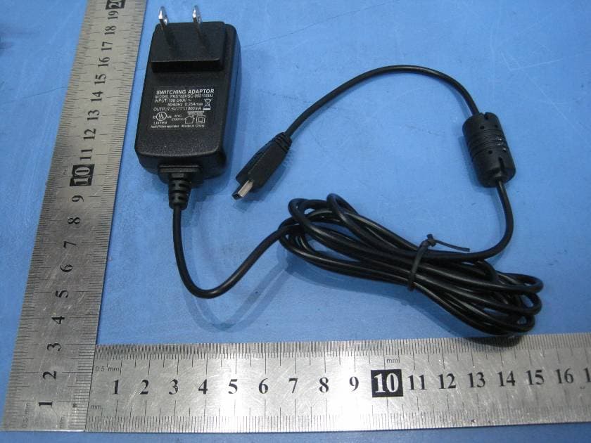
WU9ET-DM32
Sep 06, 2011H.264 DIGITAL MONITOR WITH 3.2" SCREEN
Equipment Class
DSS - Part 15 Spread Spectrum Transmitter