WVOCCTR700GPS Tracker
SHENZHEN CARSCOP ELEC CO, LTD.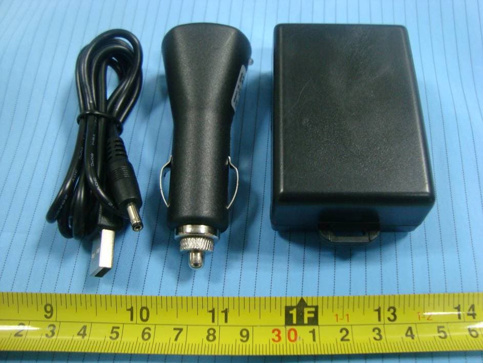
Click to zoom
Application Details
- Equipment Class
- PCB - PCS Licensed Transmitter
- Date of Grant
- Nov 14, 2010
- Application Purpose
- Original Equipment
- Date of Application
- Nov 14, 2010
- Equipment Note
- GPS Tracker
- Frequency Range
- 1850.20000000 - 1909.80000000
- Country
- China
Documents & Files
Document Text
Text extracted from the exhibit documents filed with the FCC. Open a document above to read the original.
Users Manual
1 CCTR-700 GPS TRACKER USER MANUAL ¾ Welcome to use this GPS tracker CCTR-700. It has many new functions, such as recording tracking, uploading history tracking to website, uploading current location to website, locating immediately and sending SMS with latitude and longitude, built in shock sensor to control power saving, object shock & move alarm, over area alarm, over speed alarm, emergency help etc. Many specifications are special, such as free uploading history tracking, google map link SMS locate, waterproof, magnetic pin, shock sensor control power saving, long battery life(10-15 days, standby mode), etc. ¾ It can be used as tracking cars, company vehicles, buses, taxis, trucks, elders, children, outside workers, travelers, explorers, overlanders, pets, moving equipments, transportations, criminals etc. ¾ This product is with GPS module and GSM module. The user can call the tracker with mobile phone and then the tracker will automatically hang up the call. When the GPS module received the GPS signal, it will get the latitude and longitude, and then upload the location to our website through GPRS or send the information (latitude, longitude, speed, battery, time etc) to the caller by SMS. The user can visit our free website www.followmegps.com and input the latitude and longitude information, then the location will be displayed on the map(It is unnecessary for the user to download any software, but certainly the user can change the map to satellite earth map or flat map); or the user can visit our free register website www.followmegps.net to register personal name (Use the serial number of the product to register on the website). To sign in, the user can upload the tracking to the website, and also can display the tracking on the map, which is completely free, but only available to the products from our company. ¾ Service charge is not necessary for this product, and the only charge is the SMS sending charge or GPRS data charge without voice talking charge and service charge for which the charge is very low to the user. The user can use the GSM prepaid phone card, which needs SMS, incoming caller ID display and GPRS function (If the user needs to upload the tracking through GPRS). ¾ Our free latitude and longitude located map website: http://www.followmegps.com ¾ Our free uploading tracking and displaying map website: http://www.followmegps.net ¾ Google earth down load website: http://earth.google.com z Packing list 2 ¾ GPS tracker, car charger, USB charger wire, manual. USB Charging Wire Car Adapter z Before Using At first to buy a GSM phone SIM card, which needs SMS service and incoming caller ID display function (If you’d like to upload the tracking, the card should enable GPRS function), and then to install the card to the tracker, in which, the SIM card phone number is the very tracker number and all the operations (calling and sending SMS) to the tracker is this number, such as locating immediately, add & delete preset number, changing password, enabling over speed alarm, enabling move alarm etc. 1. Power ON / OFF When power is OFF, please press the “SOS” button till the GREEN LED is ON, and then release the button and the tracker is power ON. When the LED flashes once every 4 seconds, it does mean that the tracker is ready and works well. When power is OFF, recharging the tracker will power on the tracker automatically. When the power is ON, please press the “SOS” button till the GREEN LED flashes very fast, release the button, and then press the “SOS” button 3 times, after which the GREEN LED will turn off and the tracker will power OFF. 2. Install SIM card 3 Pulling out the long narrow rubber stopple beside the tracker, you can see the SIM card socket, beside which, press the yellow switch point with a tool and then the holder will come out. Pull it out and put the SIM card in the holder and then push the holder into the tracker, (Pay attention to that the SIM card metal contact pin can not face down to the holder) at last push the long narrow rubber stopple into the tracker to cover the SIM card socket. Note: Before installing or uninstalling the SIM card, you must power off the tracker. 3. LED flash indicator GREEN LED Flash once : working well GREEN LED Flash twice : working well and GPS signal weak GREEN LED Flash three times : working well and battery low GREEN LED Flash four times : working well, battery low and GPS signal weak GREEN LED ON continuously : GSM searching network GREEN LED OFF continuously : Power off GREEN LED Flash fast : incoming or making a call or receiving a SMS RED LED Flash once : begin record tracking RED LED Flash twice : last upload tracking fail 4. Recharge the tracker Please check and confirm that the adapter model is suitable for this tracker, for which we recommend using our OEM charger to recharge the tracker. Warning: this tracker only uses the 5V DC voltage to recharge, so too high voltage or AC voltage may damage the tracker or even cause accidents. Use the USB charging wire to recharge the tracker. Pull out the rubber stopple in the power socket on the tracker, and insert the USB wire to car adapter with tracker. If the LED on the adapter is RED, it means that it is recharging, if GREEN, it means that the recharging is finished. The recharging needs about 3-4 hours to finish. Use the home AC adapter to recharge the tracker. Insert USB wire to the AC adapter, others is the same with the above. When being recharged, the tracker can work as normal. It will take about 3-4 4 hours to finish the recharging. When the battery is low, the GREEN LED on tracker will flash three times, and then the tracker will automatically send battery low information to the first preset phone number. When the battery voltage is too low, the tracker will power off automatically but when you recharge the tracker, it will power on automatically. Theoretically, the battery life can last about 10-20days. However the standby time could be shorter …
Text truncated - open the document above for the full version.
Block Diagram
BLOCK DIAGRAM Main module: GPS Module M-89 U1 GPS DATE MCU PIC18F46K20 RX IC1 TX RING GSM Module SIM900 U5 FCC ID: UDV-0912142009007 LED KEY SIM CARD POWER SUPPLLY GPS ANT 1575.42 MHz GSM ANT GSM850MHz: Tx:824-849MHz Rx:869-894 MHz PCS1900 MHz: Tx:1850-1910MHz Rx:1930-1990 MHz 16MHz TX Date Memory AT26DF161A IC2 32.768KHz Crystal X1 Crystal X2
External Photos
EXHIBIT B - EUT EXTERNAL PHOTOGRAPHS EUT – All View EUT – Front View EUT – Rear View EUT – Battery Front View EUT – Battery Rear View
ID Label/Location Info
EXHIBIT A - FCC ID LABELING AND LOCATION FCC ID Label FCC ID Label Location Label here The label shown shall be permanently affixed at a conspicuous location on the device and be readily visible to the user at the time purchase (Labeling requirements per 2.925)
Internal Photos
EXHIBIT C - EUT INTERNAL PHOTOGRAPHS EUT – Cover off View-1 EUT – Cover off View-2 EUT – Main Board Top View EUT – Main Board Bottom View Antenna EUT – SIM900 Module View
Operational Description
General Technical Description 1. Scope This document shows and provides the more detail information about the platform we used. The basic description for the Baseband and RF section are also included. SIM900 designed by SIMCOM is a quad band module which support GSM/GPRS. The baseband circuit is based on STE and RF circuit is based on RFMD. It works at quad bands, GSM850, EGSM900, DCS1800, and PCS1900 band. CPU clock is based on 26MHz crystal.The main IC include PNX4851, RF7161 and Combo Flash, etc. 2. Detail Block Diagram Figure 1 Block Diagram of SIM900 Main board working principle description 1 .Circuit description: The main board including the Power supply circuit, microprocessor circuit, shock sensor circuit; Under-Control parts including the following: GSM module, GPS module, memory, LED. 2. Principle description: The power of the main unit is supplied by the build in Li-BATTERY, also it can connect the power of 5V though the charger IC for the Li-BATTERY. It use 3.3V Regulator to drive the microprocessor, GPS power is supplied by Under-Control 3.3V Regulator. GSM module power is supplied by Li battery directly. the microprocessor receive call and SMS by GSM module then operate the circuit, control GPS module by Under-Control 3.3V Regulator to position. then process the position and send it to mobile telephone by SMS. if it is in record tracking ,The microprocessor will storage the position to the memory first then read it back and send to the website by GPRS when receiving the command. the microprocessor detect the shock sensor logic to judge if the tracker is moveing,if it isn't moving soon time. it will turn to standby mode. it also detect the key to operate and output logic high and low to control the LED. Detailed information, please refer to the following. 3. RF We use the PAM RF7161 supports the GSM/GPRS system, which include RF power amplifier and antenna switch for quad-band GSM/GPRS applications. The functional block diagram is as following. Figure 2 This design also has other RF device, such as saw filter and 26M crystal etc. 4. Baseband Baseband architecture comprises mainly 2 chips: Include PNX4851 and Combo Flash. The functional block diagram is as following. Figure 3 The Combo Flash is a Multi Chip Package Memory which combines 64M or 32M bit Nor Flash Memory and 32M or 16M bit pSRAM.
Parts List/Tune Up Info
value components Rating Footprint Amount Designator Manufacture Approval PCB:CCTR-700 1 0Ω ±5% 0603 3 R18, R20, R22 22 Ω ±5% 0603 3 R25,R26,R27 470 Ω ±5% 0603 1 R100 1K ±5% 0603 7 R7,R12,R13,R14,R17,R21,R30 3K ±5% 0603 1 R4 3.3K ±5% 0603 1 R28 4.7K ±5% 0603 2 R8, R11 10K ±5% 0603 5 R5,R6,R19,R10,R29 47K ±10% 0603 5 R2,R3,R9,R15,R16 68K ±10% 0603 1 R23 100K ±10% 0603 1 R24 27pF COG 0603 2 C16,C20 10nF X7R 0603 3 C1,C2,C3 100nF Y5V 0603 11 C6,C9,C10, C11,C13,C14,C15, C18, C19, C22, C24 1000nf Y5V 0603 1 C5 220nf Y5V 0603 1 C23 CA-10uF/10V-A Tantalumcapacitor 2 C4,C12 CA-220uF/10V Tantalumcapacitor 1 C8 DS-SK14 DIODE SMA 1 D1 YONG ER JIA WWW.WEJ.CN ICS-KF4054-4.2 IC SOT-23 1 U2 KeFa ICS-HT7333 IC SOT-89 1 U3 Holtek http://www.holtek.com ICS-MIC5219-3.3 IC SOT-23 1 U4 micrel www.micrel.com ICS-PIC18F46K20 MCU LQFP-44 1 IC1 MICROCHIP http://www.microchip.com/http://www.rohm.com.cn/ ROHM http://www.YAGEO.com/ Murata WWW.MURATA.COM YAGEO ICS-AT26DF161A IC SO-8 1 IC2 Atmel www.atmel.com SIM CARD SOCKET SOCKET 1 SIM MUP www.mupconnector.com DS-420-D CONNECTOR 1 J1 GAODI TD-15EAE-A00 KEY 1 S1 GAODI CSTCE16M0V53-R0 OSC 1 X1 Murata http://www.murata.com/ JF-32.768K ±5ppm 1X2 JF www.szjf.com double color LED LED 1D2 GUANGDA WWW.BESTLIGHTLED.COM.TW LED LED 0603 2 D3,D4 2.00mm C2 connector CONNECTOR 1 BT GAODI DA1575S18 GPS ANT 1 GPSANT C&Q http://www.szcaiqin.com.c n M-89 GPS MOUDLE 1 U1 HOLUX www.holux.com SIM900 GSM MOUDLE 1 U5 SIMCOM www.sim.com GSM ANT GSM ANT 1 GSMANT HTW SHOCK SENSOR SENSOR 1 S2 n /
RF Exposure Info
SHENZHEN CARSCOP ELEC CO, LTD. FCC ID: WVOCCTR700 Report No.: RSZ10012703 Page 7 of 17 FCC Part 22H/24E Test Report FCC §1.1307 (b) (1) & §2.1091- MAXIMUM PERMISSIBLE EXPOSURE (MPE) Applicable Standard According to §1.1307(b)(1), systems operating under the provisions of this section shall be operated in a manner that ensures that the public is not exposed to radio frequency energy level in excess of the Commission’s guidelines. According to §1.1310 and §2.1091 RF exposure is calculated. Limits for General Population/Uncontrolled Exposure Limits for General Population/Uncontrolled Exposure Frequency Range (MHz) Electric Field Strength (V/m) Magnetic Field Strength (A/m) Power Density (mW/cm 2 ) Averaging Time (minutes) 0.3-1.34 614 1.63 *(100) 30 1.34-30 824/f 2.19/f *(180/f 2 ) 30 30-300 27.5 0.073 0.2 30 300-1500 / / f/1500 30 1500-100,000 / / 1.0 30 Note: f = frequency in MHz * = Plane-wave equivalent power density Test Data Predication of MPE limit at a given distance Where: S = power density (in appropriate units, e.g. mW/cm2) P = output power to antenna G= Antenna Gain R = distance to the center of radiation of the antenna (appropriate units, e.g., cm) Antenna Gain Conducted Power Radio Band (dBi) (numeric) Time Slot (dBm)(mW) Duty factor Time- Averaged Transmit Power (mW) Evaluation Distance (cm) Calculated Power Density (mW/cm 2 ) MPE Limit (mW/cm 2 ) -2.97 0.505 1 slot 33.1 20421/8 255.25 20 0.0256 0.55 GSM850 -2.97 0.505 2 slot 33.1 20421/4 510.5 20 0.0513 0.55 -1.97 0.635 1 slot 30.5 11221/8 140.25 20 0.0177 1.0 PCS1900 -1.97 0.635 2 slot 30.3 10721/4 268 20 0.0339 1.0 Result: The MPE of device complies at 20 cm distance.
Schematics
1 1 2 2 3 3 4 4 5 5 6 6 7 7 8 8 DD CC BB AA VCC 1 GND 2 BOOT_SELECT 3 RXD1 4 TXD1 5 TXD2 6 RXD2 7 SPI_EN 8 VCCGSP3 9 GND 10 RF_GND 11 RF_GND 12 RF_GND 13 RF_GND 14 RF_GND 15 RF_GND 16 RF_IN 17 RF_GND 18 V_ANT 19 VCCRF 20 V_BAT 21 RESET_N 22 VCC 23 SPI_DATA 24 NADC_D 25 SPI_CLK 26 GP100 27 ODOMETER 28 T_MARK 29 GND 30 U1M-89 C1 103P C2 103P C3 103P C4 10uF/10V R1 103/471 R2 473 R3 473 GPSANT ANT GPS_3.3V 3.3V GPSTXD C23 224P Vin 1 G N D 2 Vout 3 U37333 C6 104 C9 104P OUT 5 VIN 1 ADJ 4 G N D 2 ON/OFF 3 U45219-3.3V R5 103 GPS_CON VBAT + C12 10uF/10v VBAT 3.3V + C8 220uF 3.3V GPS_3.3V S1 SW R13 102 R21 102 C19 104P C18 104P BT1 BAT 1 2 J1 CON2 C15 104P 3.3V DCIN 3.3V RESET_SYS I/O 1 OPEN 2 GND 3 VCC 4 RST 5 CLK 6 DET1 7 DET2 8 SIM SIMCARD R25 22Ω R26 22Ω R27 22Ω R19 103 SM_VDD R6 103 R23 683 R24 104 SMIO SMCLK SMRST LED2 CHRG 1 G N D 2 BAT 3 V C C 4 PROG 5 U24054-4.2V C5 105 R4 222 VCC_IN VCC_IN VCC_4.2 VCC_4.2 D1 SK14 C10 NC R7 102 R28 332 C22 104P 3.3V RESET_SYS GPSTXD SIM300_DCD SIM300_DTR SIM300_RXD SIM300_TXD SIM300_RTS SIM300_CTS SIM300_RI SIM300_RST GPS_CON R14 102 R17 102 1 2 3 4 5 6 J3 CON6 VPP VPP 3.3V R C 7 / R X /D T 1 R D 4 / PS P 4 2 R D 5 / PS P 5 / P1 B 3 R D 6 / PS P 6 / P1 C 4 R D 7 / PS P 7 / P1 D 5 V S S 6 V D D 7 R B 0 / A N 1 2 / I N T 0 8 R B 1 / A N 1 0 / I N T 1 9 R B 2 / I N T 2 /A N 8 1 0 R B 3 / A N 9 / C C P 2 1 1 NC 12 NC 13 RB4/AN11 14 RB5/PGM 15 RB6/PGC 16 RB7/PGD 17 MCLR/VPP/RE3 18 RA0/AN0 19 RA1/AN1 20 RA2/AN2 21 RA3/AN3 22 R A 4 / T 0 C K I 2 3 R A 5 / A N 4 / S S 2 4 R E 0 / A N 5 / R D 2 5 R E 1 / W R / A N 6 2 6 R E 2 / C S /A N 7 2 7 V D D 2 8 V S S 2 9 R A 7 / O S C 1 /C L K I N 3 0 R A 6 / O S C 2 /C L K OU T 3 1 R C 0 / T 1 O S O 3 2 N C 3 3 NC 34 RC1/T1OSI 35 RC2/CCP1/P1A 36 RC3/SCK/SCL 37 RD0/PSP0 38 RD1/PSP1 39 RD2/PSP2 40 RD3/PSP3 41 RC4/SDI/SDA 42 RC5/SDO 43 RC6/TX/CK 44 IC118F46K20 3.3V 3.3V C11 104p C13 103 21 X116M C7 9P C26 9P VDD_EXT R16 473 R15 473 R9 473 3.3V PGC PGC R10 103 RESET_SYS SPI_CS SPI_CLK SPI_DI SPI_DO 21 X232.768k C20 27P C16 27P /CS 1 SO 2 /WP 3 GND 4 SI 5 SCK 6 /HOLD 7 VCC 8 IC2AT26DF161A 3.3V SPI_CS SPI_DI SPI_DO SPI_CLK DCIN R8 RES1 D3 LED G P S L E D GPSLED D2LED R12 102 LED1 LED1 LED2 VCC_4.2VBAT R29 103 R30 102 C24 104P S2 SENSOR 3.3V SENSOR SENSOR PWRKEY 1 PWRKEY_OUT 2 DTR 3 RI 4 DCD 5 DSR 6 CTS 7 RTS 8 TXD 9 RXD 10 DISP_CLK 11 DISP_DATA 12 DISP_D/C 13 DISP_CS 14 VDD_EXT 15 NRESET 16 GND 17 G N D 1 8 M I C _ P 1 9 M I C _ N 2 0 S PK _ P 2 1 S PK _ N 2 2 L I N E I N _ R 2 3 L I N E I N _ L 2 4 A D C 2 5 V R T C 2 6 D B G _ T X D 2 7 D B G _ R X D 2 8 G N D 2 9 S I M _ V D D 3 0 S I M _ D A T A 3 1 S I M _ C L K 3 2 S I M _ R S T 3 3 S I M _ PR E S E N C E 3 4 PWM1 35 PWM2 36 SDA 37 SCL 38 GND 39 GPIO1/KBR4 40 GPIO2/KBR3 41 GPIO3/KBR2 42 GPIO4/KBR1 43 GPIO5/KBR0 44 GND 45 GND 46 GPIO6/KBC4 47 GPIO7/KBC3 48 GPIO8/KBC2 49 GPIO9/KBC1 50 GPIO10/KBC0 51 N E T L I GH T 5 2 G N D 5 3 G N D 5 4 V B A T 5 5 V B A T 5 6 V B A T 5 7 G N D 5 8 G N D 5 9 R F_ A N T 6 0 G N D 6 1 G N D 6 2 G N D 6 3 G N D 6 4 G N D 6 5 S T A T U S 6 6 G P I O 1 1 6 7 G P I O 1 2 6 8 SIM900 SIM300_RXD SIM300_TXD 12 J4 CON2 V D D _ E X T S M I O S M C L K S M R S T S M _ V D D SIM300_RI SIM300_RST + C17 Comment: NC SIM300_CTS SIM300_RTS SIM300_DTR SIM300_DCD C14 104P R11 103 D4 LED GSMANT R22 0 NC RESET RESET R18 0 C25 NC C21 NC Company Model Data Title Product TypeTracker CCTR700.SCH CCTR700 SHENZHEN CARSCOP ELECTRONICS CO.,LTD 2010.08.09 SIM 900 U5 FCC ID:UDV-0912142009007 GSM 850: 824-849MHz 869-894MHz PCS 1900:1850-1910MHz 1930-1990MHz 1575.42 MHz
Test Report
Note: This test report is prepared for the customer shown above and for the device described herein. It may not be duplicated or used in part without prior written consent from Bay Area Compliance Laboratories Corp. This report must not be used by the customer to claim product certification, approval, or endorsement by NVLAP*, NIST, or any agency of the Federal Government. * This report may contain data that are not covered by the NVLAP accreditation and are marked with an asterisk “*” (Rev.2) FCC PART 22H & 24E MEASUREMENT AND TEST REPORT For SHENZHEN CARSCOP ELEC CO, LTD. Buliding A1, YuanLing North Road, EGongLing Village, PingHu Town, Shenzhen, Guangdong, China. FCC ID: WVOCCTR700 Report Type: Original Report Product Type: GPS TRACKER Test Engineer: Felix Li Report Number: RSZ10012703 Report Date: 2010-11-03 Reviewed By: Merry Zhao EMC Engineer Prepared By: Bay Area Compliance Laboratories Corp. (Shenzhen) 6/F, the 3rd Phase of WanLi Industrial Building, ShiHua Road, FuTian Free Trade Zone Shenzhen, Guangdong, China Tel: +86-755-33320018 Fax: +86-755-33320008 SHENZHEN CARSCOP ELEC CO, LTD. FCC ID: WVOCCTR700 Report No.: RSZ10012703 Page 2 of 17 FCC Part 22H/24E Test Report TABLE OF CONTENTS GENERAL INFORMATION.......................................................................................................................................3 PRODUCT DESCRIPTION FOR EQUIPMENT UNDER TEST (EUT) ....................................................................................3 OBJECTIVE...................................................................................................................................................................3 RELATED SUBMITTAL(S)/GRANT(S).............................................................................................................................3 TEST METHODOLOGY..................................................................................................................................................3 TEST FACILITY.............................................................................................................................................................4 SYSTEM TEST CONFIGURATION ..........................................................................................................................5 JUSTIFICATION.............................................................................................................................................................5 EQUIPMENT MODIFICATIONS.......................................................................................................................................5 CONFIGURATION OF TEST SETUP.................................................................................................................................5 BLOCK DIAGRAM OF TEST SETUP................................................................................................................................5 SUMMARY OF TEST RESULTS ...............................................................................................................................6 FCC §1.1307 (B) (1) & §2.1091- MAXIMUM PERMISSIBLE EXPOSURE (MPE)...................................................7 APPLICABLE STANDARD..............................................................................................................................................7 TEST DATA..................................................................................................................................................................7 FCC §2.1047 - MODULATION CHARACTERISTIC ..............................................................................................8 FCC § 2.1046, § 22.913 (A) & § 24.232 (C) - RF OUTPUT POWER........................................................................9 APPLICABLE STANDARD..............................................................................................................................................9 TEST PROCEDURE........................................................................................................................................................9 TEST EQUIPMENT LIST AND DETAILS...........................................................................................................................9 TEST DATA................................................................................................................................................................10 FCC §2.1049, §22.917, §22.905 & §24.238 - OCCUPIED BANDWIDTH ..............................................................11 APPLICABLE STANDARDS...........................................................................................................................................11 TEST DATA................................................................................................................................................................11 FCC §2.1051, §22.917(A) & §24.238(A) - SPURIOUS EMISSIONS AT ANTENNA TERMINALS ..................12 APPLICABLE STANDARDS...........................................................................................................................................12 TEST DATA................................................................................................................................................................12 FCC §2.1053, §22.917 & §24.238 - SPURIOUS RADIATED EMISSIONS ...........................................................13 APPLICABLE STANDARDS...........................................................................................................................................13 TEST PROCEDURE......................................................................................................................................................13 TEST EQUIPMENT LIST AND DETAILS......................................................................................................................…
Text truncated - open the document above for the full version.
Test Setup Photos
EXHIBIT D - TEST SETUP PHOTOGRAPHS Below 1GHz: Spurious Radiated Emissions - Front View Below 1GHz: Spurious Radiated Emissions - Rear View Above 1GHz: Spurious Radiated Emissions - Front View Above 1GHz: Spurious Radiated Emissions - Rear View
Contact Information
Applicant
Te Qi Fu(Deputy General Manager)
Test Firm
Bay Area Compliance Laboratory Corp. (Shenzhen)John Chan
Technical Specifications
| # | Rule Parts | Frequency Range | Power Output | Emission | Tolerance |
|---|---|---|---|---|---|
| 2 | 24E | 1.85 GHz - 1.91 GHz | 1.12 W | 247KGXW | 2.5 ppm |