WWLAMB4Wireless Mouse
ATake Digital Technology ShenZhen Co.,Ltd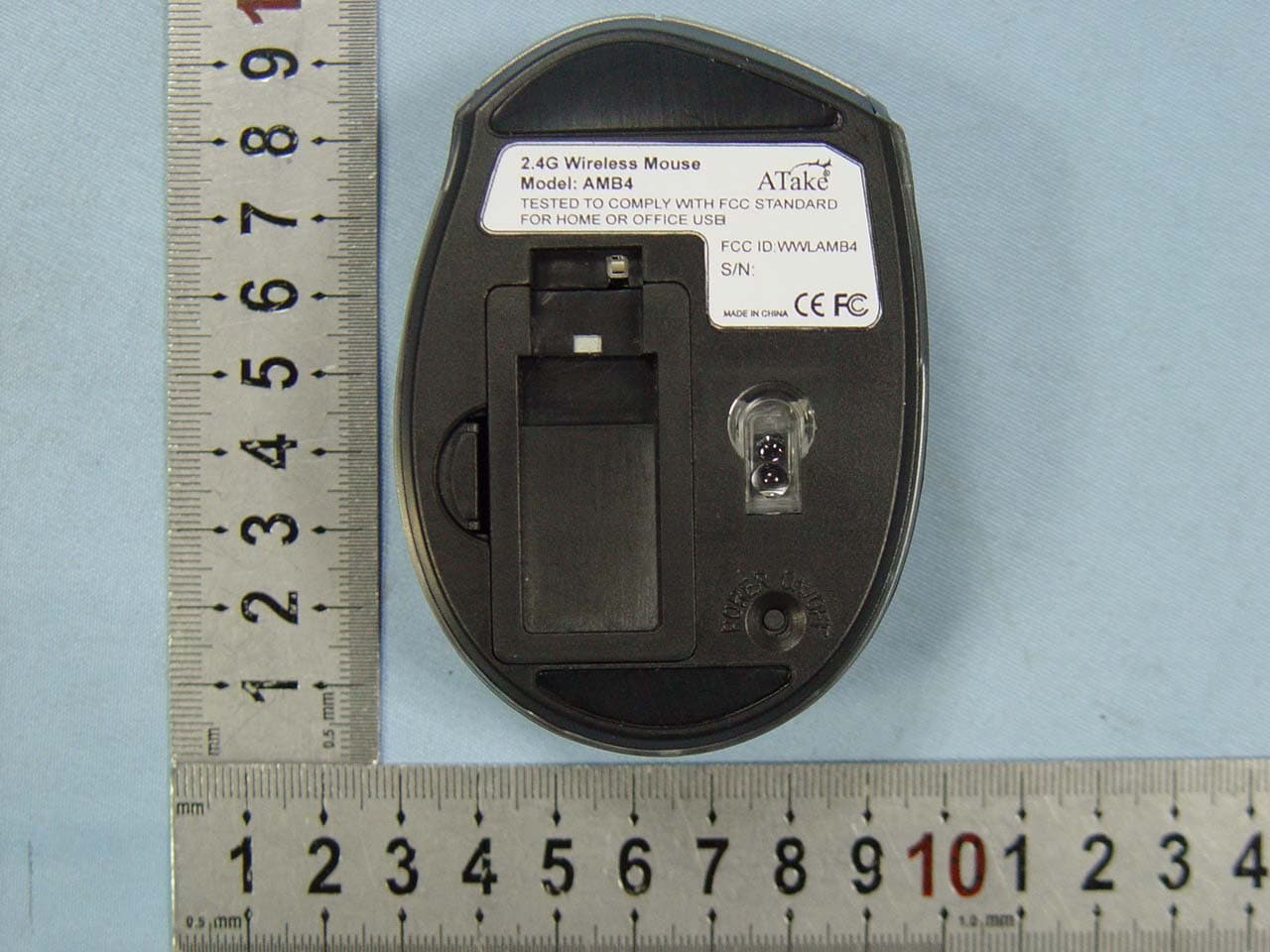
Click to zoom
Application Details
- Equipment Class
- DXX - Part 15 Low Power Communication Device Transmitter
- Date of Grant
- Feb 09, 2010
- Application Purpose
- Original Equipment
- Date of Application
- Feb 09, 2010
- Equipment Note
- Wireless Mouse
- Frequency Range
- 2403.00000000 - 2473.00000000
- Country
- China
Documents & Files
Document Text
Text extracted from the exhibit documents filed with the FCC. Open a document above to read the original.
Users Manual
Wireless Mouse User Manual Thank you for purchasing the ATake Wireless Laser Mouse. Combining a modern design with advanced performance, the ATake Wireless Laser Mouse features an push-button that instantly shifts resolution (800/1600 dpi) to suit a wide range of applications. The auto power management and an on/off switch are designed to help maintain proper battery levels. The easy-to-follow instructions in this manual help make installation of the mouse quick and simple, so you’ll also soon be enjoying the benefits of these additional features: • 2.4 GHz RF technology offers wireless freedom with effective range up to 10m • Compact size, ergonomic shape and no-slip texture provide secure grip • Low-friction base smoothly glides over work surfaces • Plug and Play installation — Windows and Mac compatible • One-Year Limited Warranty INSTALLATION/SETUP Batteries On the underside of the mouse, push the battery compartment cover release in and remove the battery compartment cover. Insert the two AAA batteries, matching the polarity indicators on the inside of the compartment. Replace the cover, pressing gently till it clicks in place. DPI (Resolution) Switch Push the button on top of the mouse to shift resolution between 800 and 1600 dpi to suit a wide range of applications. OPERATION Operate the mouse within 10 m Place the mouse on a white or light-colored surface for optimal performance. When the mouse is not in use, set the power switch to Off. If the mouse will not be used for an extended period of time or if you transport the device outdoors, it’s best to remove the batteries. The mouse automatically enters a sleep mode after a period of inactivity to save power. Press any key or scroll to wake it. Laser synchronization is automatic: No settings are necessary. SPECIFICATIONS Standards and Certifications • FCC • CE General • RF wireless range: up to 10 m • Mouse: laser (Class 1); 800/1600 dpi resolution • Controls: right, left and center mouse buttons with scroll wheel; page forward and page backward side buttons; power switch (on/off); resolution adjustment button • Material: ABS plastic • Compatible with Windows XP/Vista/7 and Mac OS 9.0 and higher Dimensions • Mouse: 92.6 x 56.9 x 33.4 mm; 60 g • USB nano receiver: 19 x 6.4 x 14.8 mm Environmental • Operational temperature: -5 - 40°C • Storage temperature: -15 - 60°C • Working humidity: <90% • Electrical: 3 V <3 mA Package Contents • ATake Wireless Laser Mouse • 2 AAA alkaline batteries • User manual FCC STATEMENT 1. This device complies with Part 15 of the FCC Rules. Operation is subject to the following two conditions: (1) This device may not cause harmful interference, and (2) This device must accept any interference received, including interference that may cause undesired operation. 2. Changes or modifications not expressly approved by the party responsible for compliance could void the user’s authority to operate the equipment. NOTE: This equipment has been tested and found to comply with the limits for a Class B digital device, pursuant to Part 15 of the FCC Rules. These limits are designed to provide reasonable protection against harmful interference in a residential installation. This equipment generates, uses and can radiate radio frequency energy and, if not installed and used in accordance with the instructions, may cause harmful interference to radio communications. However, there is no guarantee that interference will not occur in a particular installation. If this equipment does cause harmful interference to radio or television reception, which can be determined by turning the equipment off and on, the user is encouraged to try to correct the interference by one or more of the following measures: -- Reorient or relocate the receiving antenna. -- Increase the separation between the equipment and receiver. -- Connect the equipment into an outlet on a circuit different from that to which the receiver is connected. -- Consult the dealer or an experienced radio/TV technician for help.
Block Diagram
1234 A B C D 4 321 D C B A Title NumberRevisionSize A4 Date:1-Feb-2010 Sheet of File:D:\MY\2010120.ddbDrawn By: MCU U1 CX5183 U1 24C02 SCLSDL 4MHZ Z AXIS VCC3.3v S-MISO RET S-CLK S-MOSI S-SS FLG SENSOR U2 ADNS7530S VCC2.7V LED LENS VCC2.7W MUTTON U5 Boost SCLK SDIO L MR RF IC U3 SGN6210_QFN24 ANT 12MHZ 1.8V LDO VCC1.8v PDF 文件使用 "pdfFactory Pro" 试用版本创建 www.fineprint.cn
ID Label/Location Info
FCC Certification Label Sample
ID Label/Location Info
FCC Certification Label Location Sample Label location
Internal Photos
Antenna
Operational Description
Applicant:Atake Digital Technology ShenZhen Co., Ltd. FCC ID:WWLAMB4 Operation Description The transmitter use a MCU chip CX5183, most of function can be finished by one chip, such as key-press detective. The transmitter is made of U1(CX5183), RF IC U3( SGN6210) ,SENSOR U5(A7530), U2 is ID code storage IC, U4 is power management IC ,U4 is the circuit of boost pressure, it make the battery’s voltage reach 3V to support the mouse working .Clock oscillator is made of U1 internal circuit and Y1 surrounding circuit , and it can supply the power for clock pulse. Once start the LB, RB, MB, ZB switch, U1 will be process. U5 is optical chip, it can react the movement of tabletop then deliver to U1, U1 will finish all the data encode internal, then deliver to U3( SGN6210), this signal will be modulated and amplified, at last it delivered to the air by antenna . U2 is ID code memory, after the mouse and receiver code connect together successfully, U2 will record this code and backup it for next time. Antenna is formed by a copper trace on the PCB. Common grounding on PCB is not connected to real external ground. Power supply is DC 3V by two “AAA” batteries.
Schematics
123456 A B C D 6 54321 D C B A COMPANY: ATAKE(威立达科技) TITLE: REV: ver 3.0 NO: DATE:2009/08/25 SPI~MOSI SPI~MISO SNS~SS SPI~CLK Mouse _ADNS7530 1 2 3 SW1 编码器 ZA ZB ZC R0 R1 R2 R3 LB RB MB FB CBDIPB BB C0 E4 10uF C7 104 +VE 1 LNEN 2 NCS 3 MISO 4 SCLK 5 MOSI 6 MOT 7 LASER 8 VDD 9 NC 10 GND 11 VDD 12 RefA 13 DGND 14 VDDIO 15 -VE 16 U5 ANDS7530 Q1AF2301 R161K C8 470pF E6 10uF C9 104 VCC E5 1uF C4 103 MOT VE- VE- VCC R8/*1K R9/*1K E2 47uF C6 104 L1 100uH D11N5819 E3 100uF/16V VCC BLOW BT- BT+ 1 2 BAT1 1节或2节电池 BT+ 1 23 OUT VSS LX U4 ME2100A-27P 1 3 2 VDD VSS OUT DE1 ME2801A-22M/* ** 低电压检测电路可选 1)使用2节电池时用2.2V检测IC 2)使用1节电池时用1.1V检测IC A0 1 A1 2 A2 3 A3 4 SDA 5 SCL 6 WP 7 VCC 8 U2 24LC01/02 R4 10K VCC EEP~DAT EEP~CLK LED1 FC/BL LED R11 1K/* VCC SNS~SS R5 100K VCC RF~PKT RF~SS SPI~MISO SPI~CLK SPI~MOSI MOT ZA ZB EEP~CLK EEP~DAT BLOW TCCVCC VCC OSCI OSCO Y1 4MHz C2 33PF C1 33PF C3 104 R17 1M C0 R0R1 R2 R3 R14470K VCC R10470K VCC CX5183-SSOP24 PA6 1 TCC 2 VCC 3 VSS 4 PA0 5 PA1 6 PA2 7 PA3 8 PB0 9 PB1 10 PB2 11 PB4 12 PB5 13 PB6 14 PB7 15 PC0 16 PC1 17 PC2 18 PC6 19 PC7 20 OSCO 21 OSCI 22 RESET 23 PA7 24 U1 Sensor方向选择 注: TCC接SPI~MOSI为进入EMI测试模式 TCC接EEP~CLKTCC接EEP~DAT TCC接C0 TCC接VCC R4 10 S~MOSI FLG S~SS S~CLK S~MISO RET VD33 ANTENNA C9 2.2uF C50.10uF +1.8V C11 0.01uF C10 0.1uF +1.8V C2 33pF C6 0.10uF C8 0.10uF C1 33pF +1.8V +1.8VVDD33 R2 2.2K R1 680K 43 21 Y1 12MHz(+-10ppm)/20pf XI 1 PLL_Vdd 2 VCO_Vdd 3 ANT 4 DBG 5 RF_Vdd 6 IF_Vdd 7 AMS_AVdd 8 BXTLEN 9 RXCLK 10 BPKTCTL 11 vss_dig 12 vdd_dig 13 BNDEN 14 BDATA 15 BDCLK 16 BNPWR 17 BDATA1 18 Vdd_io 19 Ldo_vout 20 CKPHA 21 Ams_DVss 22 AMS_DVdd 23 XO 24 Die 25 U1 SGN6210_QFN24 A1 +1.8V C14 * C15 * C13 * *C13/14/15 视天线需调整 PDF 文件使用 "pdfFactory Pro" 试用版本创建 www.fineprint.cn
Test Report
Page 1 of 46 FCC ID: WWLAMB4 ACCURATE TECHNOLOGY CO. LTD REPORT NO. ATE20100158 FCC CERTIFICATION On Behalf of Atake Digital Technology ShenZhen Co., Ltd. Wireless Mouse Model No.: AMB4, AMH, AMR, AMX FCC ID: WWLAMB4 Prepared for : Atake Digital Technology ShenZhen Co., Ltd. Address : 13 th Building, The 4 th Industry park, Han Shui Ko, Kong Ming Town, ShenZhen City, China Prepared by : ACCURATE TECHNOLOGY CO. LTD Address : F1, Bldg. A, Changyuan New Material Port, Keyuan Rd. Science & Industry Park, Nanshan, Shenzhen, Guangdong P.R. China Tel: (0755) 26503290 Fax: (0755) 26503396 Report Number : ATE20100158 Date of Test : February 2-3, 2010 Date of Report : February 6, 2010 Page 2 of 46 FCC ID: WWLAMB4 ACCURATE TECHNOLOGY CO. LTD REPORT NO. ATE20100158 TABLE OF CONTENTS Description Page Test Report Certification 1.GENERAL INFORMATION ..........................................................................................................4 1.1.Description of Device (EUT)....................................................................................................................4 1.2.Description of Test Facility ......................................................................................................................4 1.3.Measurement Uncertainty.........................................................................................................................5 2.MEASURING DEVICE AND TEST EQUIPMENT ..................................................................... 6 3.SUMMARY OF TEST RESULTS................................................................................................... 7 4.FUNDAMENTAL AND HARMONICS RADIATED EMISSION FOR SECTION 15.249(A) 8 4.1.Block Diagram of Test Setup....................................................................................................................8 4.2.The Emission Limit ..................................................................................................................................9 4.3.Configuration of EUT on Measurement ...................................................................................................9 4.4.Operating Condition of EUT ....................................................................................................................9 4.5.Test Procedure ........................................................................................................................................10 4.6.The Field Strength of Radiation Emission Measurement Results ..........................................................11 5.SPURIOUS RADIATED EMISSION FOR SECTION 15.249(D) ............................................. 14 5.1.Block Diagram of Test Setup..................................................................................................................14 5.2.The Emission Limit For Section 15.249(d) ............................................................................................15 5.3.EUT Configuration on Measurement .....................................................................................................15 5.4.Operating Condition of EUT ..................................................................................................................15 5.5.Test Procedure ........................................................................................................................................16 5.6.The Emission Measurement Result ........................................................................................................17 6.BAND EDGES ................................................................................................................................. 20 6.1.The Requirement ....................................................................................................................................20 6.2.EUT Configuration on Measurement .....................................................................................................20 6.3.Operating Condition of EUT ..................................................................................................................20 6.4.Test Procedure ........................................................................................................................................20 6.5.The Measurement Result ........................................................................................................................21 7.ANTENNA REQUIREMENT........................................................................................................ 23 7.1.The Requirement ....................................................................................................................................23 7.2.Antenna Construction .............................................................................................................................23 APPENDIX I ( TEST CURVES) (22 pages) Page 3 of 46 FCC ID: WWLAMB4 ACCURATE TECHNOLOGY CO. LTD REPORT NO. ATE20100158 Test Report Certification Applicant : Atake Digital Technology ShenZhen Co., Ltd. Manufacturer : Atake Digital Technology ShenZhen Co., Ltd. EUT Description : Wireless Mouse (A) MODEL NO.: AMB4, AMH, AMR, AMX (B) SERIAL NO.: N/A (C) POWER SUPPLY: 3V DC (“AAA” batteries 2h) Measurement Procedure Used: FCC Rules and Regulations Part 15 Subpart C Section 15.249 ANSI C63.4: 2003 The device described above is tested by ACCURATE TECHNOLOGY CO. LTD to determine the maximum emission levels emanating from the device. The maximum emission levels are compared to the FCC Part 15 Subpart C Section15.249 limits. The measurement results are contained in this test report and ACCURATE TECHNOLOGY CO. LTD is assumed full responsibility for the accuracy and completeness of these measurements. Also, this report shows that the Equipment Under Test (EUT) is to be technically compliant with the FCC requirements. This report applies to above tested sample only. This report shall not be re…
Text truncated - open the document above for the full version.
Test Setup Photos
Radiated emissions test < 1GHz Radiated emissions test > 1GHz
Contact Information
Applicant
limei Wang
Test Firm
Accurate Technology Co., Ltd.Sean Liu
Technical Specifications
| # | Rule Parts | Frequency Range | Power Output |
|---|---|---|---|
| 1 | 15C | 2.40 GHz - 2.47 GHz | - |
Other Applications from ATake Digital Technology ShenZhen Co.,Ltd

WWLDKB5101
Jan 09, 2012Wireless Keyboard
Equipment Class
DXX - Part 15 Low Power Communication Device Transmitter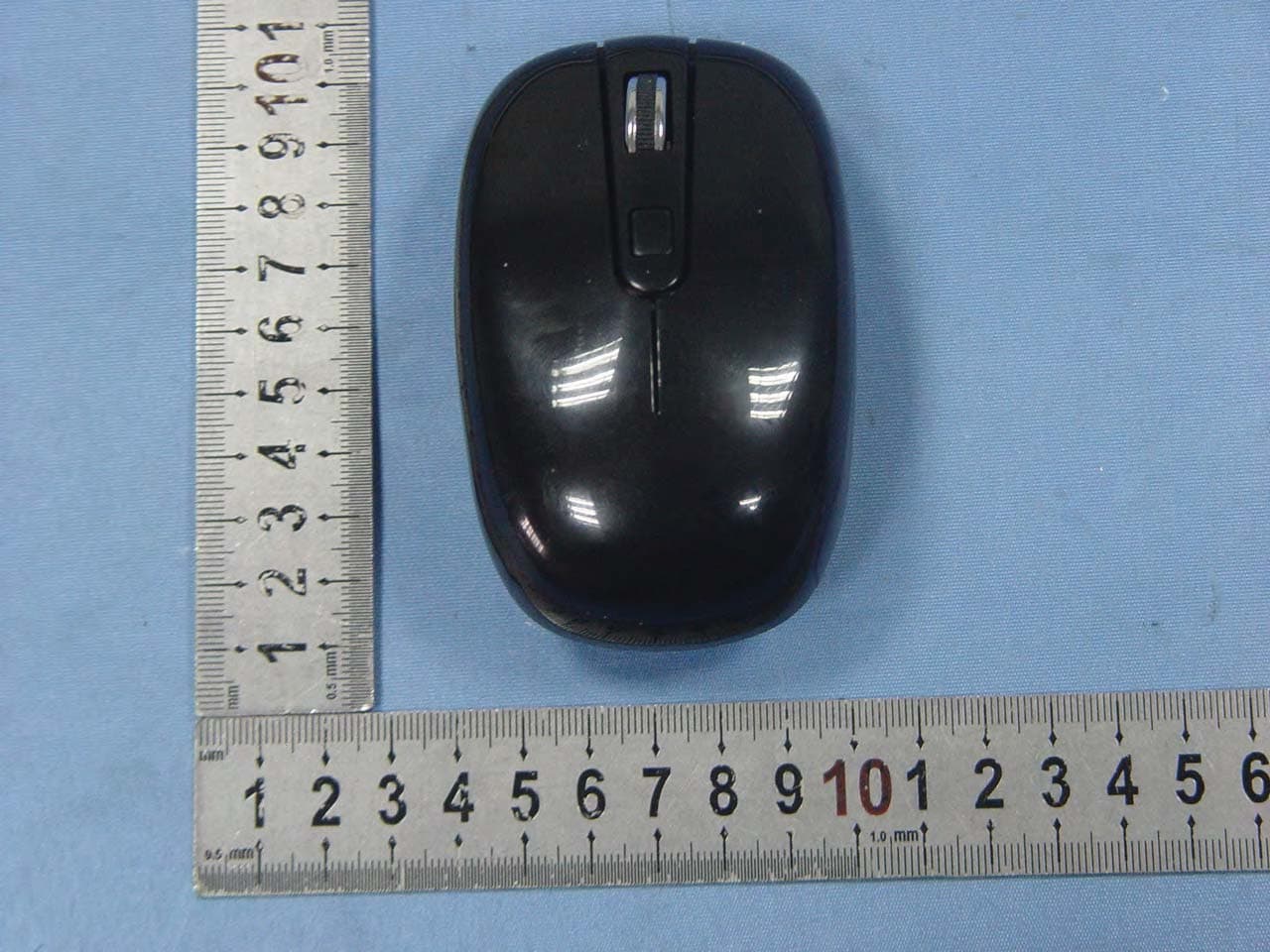
WWLAMS-700
Jan 07, 2012Wireless Mouse
Equipment Class
DXX - Part 15 Low Power Communication Device Transmitter