WYQ-BTH5S2AM/FM Radio Headset with BT and Aux-in Jack
SPECIALTHING INTERNATIONAL CO, LTD
Click to zoom
Application Details
- Equipment Class
- DSS - Part 15 Spread Spectrum Transmitter
- Date of Grant
- Dec 04, 2014
- Application Purpose
- Original Equipment
- Date of Application
- Dec 03, 2014
- Equipment Note
- AM/FM Radio Headset with BT and Aux-in Jack
- Frequency Range
- 2402.00000000 - 2480.00000000
- Country
- Hong Kong
Documents & Files
Document Text
Text extracted from the exhibit documents filed with the FCC. Open a document above to read the original.
Users Manual
MODEL NUMBER: HP-52RBJ DIGITAL AM / FM STEREO HEADPHONE RADIO WITH BLUETOOTH & AUX-IN JACK USER MANUAL When the headset is turned on, all settings are resumed to the last (previous) settings. For U.S.A. users, 10 kHz is recommended. To select 9 or 10 kHz for AM, the procedure is as shown here below: Keep unit in OFF position. During time setting mode, press button for 2 seconds. 9 kHz will be shown on the display. Press Scan or to select 10 kHz. After selection, turn on the headset to activate the Radio. - Insert Battery Turn off the headset. Open the battery door, insert 3 pieces AAA sized batteries. Close the battery door. - Time Setting Turn off the headset by turning the volume knob in anti clockwise direction. Press button or to select 12 or 24-hours mode. Turn off the headset by turning the volume knob in anti clockwise direction. Press MODE button. When time is flashing, press ▲ or ▼ to adjust the hour, then press MODE to confirm. Then adjust minutes, apply same procedure as above, then press MODE button to confirm the setting. Radio Mode Turn on the headset by tuning the Power ON/OFF Knob (which combines with Volume Control) in clockwise direction. Tap quickly the button to toggle between FM/AM/BT Setting. Set to AM or FM to listen to radio. Manual search: Press ▲ or ▼ (scan) buttons step by step until it reaches your desired station. Auto Scan: Press ▲ or ▼ (scan) buttons for 2 seconds, then release the button when seeking starts. Auto scan will stop on clear radio stations. Preset Station: 10 preset stations in AM band and FM band. Total is 20 preset stations. Hold MODE button, then release the button when M and the preset station number are flashing. Press ▲ or ▼ to save the station to your desired position. Press MODE button to confirm your setting. Listen to the preset status by pressing the MODE button once to select preset stations M[1] to M[10]. - BT Mode Turn on the Bluetooth function on your mobile phone or any other external Bluetooth devices. Tap the button to toggle between FM/AM/BT Setting. Select () to activate the Bluetooth function. In your Bluetooth device, seek HP-53RBJ and pair. After paired, - on - is shown on the LCD. To disable Bluetooth function, press and hold the button for 2 seconds. OFF will shown on the display. Press MODE to play/pause the music or answer the call. Tap ▲ or ▼ to forward/rewind the songs. To reject the call, tap button. Hold button for 2 seconds, breaks the current BT connection (this function is disabled during phone call). After paired, user still receives and answers call while in Radio and Aux-in mode. - BT + Radio After paired the Bluetooth device, tap the button to select AM or FM. When there is an incoming call, a telephone ring tone is heard. Press MODE button to answer the call or to reject the call. After call ending, radio will be resumed automatically. - Auxiliary Jack Operation Using a Ø3.5 mm cable to connect the headset with external audio device. Aux in appears in the screen when it is plugged. - BT + Auxiliary Jack Operation Activate BT function to pair the headset and mobiles. Plug into the auxiliary jack by using a Ø3.5 mm cable to connect with the cell phone or other audio devices. When there is an incoming call, a telephone ring tone is heard. Press MODE button to to answer the call or to reject the call. Precautions and warnings: The radio reception may be distorted during moving. Interference and fault may happen when turn on the TV, fluorescent light or other electrical appliances. When the volume begins to fade, change both batteries. Should not use the headset under a high temperature or high humidity environment as it may damage the receiver. Exposure to direct sunlight in places where may cause the case of the unit to warp or malfunction. The temperature should not exceed + 55°C. Battery shall not be exposed to excessive heat, such as sunshine, fire or the like. This product may be adversely affected by certain chemical substances. Simply wipe it with a soft cloth moistened with a mild soap or water. Do not dip into the water. Failure to follow the instruction or misuse the headset can result in injury and/or loss. If the recommendation given in Fitting Instruction is not adhered to, the protection afforded by the ear-muffs will be severely impaired. Headband and cushion is non-replaceable, do not tear it off as it will damage the headset. This device complies with Part 15 of the FCC Rules. Operation is subject to the following two conditions: (1) this device may not cause harmful interference, and (2) this device must accept any interference received, including interference that may cause undesired operation. Notice Concerning FCC Regulations: You are cautioned that changes or modifications not expressly approved by the party responsible for compliance could void the user’s authority to operate the equipment. This equipment has been tested and found to comply with the limits for a Class B digital device, pursuant to Part 15 of the FCC Rules. These limits are designed to provide reasonable protection against harmful interference in a residential installation. This equipment generates, uses and can radiate radio frequency energy and, if not installed and used in accordance with the instructions, may cause harmful interference to radio communications. However, there is no guarantee that interference will not occur in a particular installation. If this equipment does cause harmful interference to radio or television reception, which can be determined by turning the equipment off and on, the user is encouraged to try to correct the interference by one or more of the following measures: -- Reorient or relocate the receiving antenna. -- Increase the separation between the equipment and receiver. -- Connect the equipment into an outlet on a circuit different from that to which the receiver is connected. -- Consult the dealer or an expe…
Text truncated - open the document above for the full version.
Cover Letter(s)
SCS-F18: Project and Product Certification Representative Authorization Letter Page 1 of 2 Rev 5.0 775 Montague Expressway Milpitas, CA 95035 Tel: 408-526-1188 Fax: 408-526-1088 Email: [email protected] Project and Product Certification Representative Authorization Letter Revision History Reason for Amendment (current / obsolete) From To Approved Date Initial Release (obsolete) 1.0 1.0 Nov-14-2006 Revised wording (obsolete) 1.0 2.0 Sept–25-2007 Updated company template (obsolete) 2.0 3.0 Jan-31-2012 Updated letter information (obsolete) 3.0 4.0 May-23-2014 Added FCC ID field (current) 4.0 5.0 Sept 16 2014 SCS-F18: Project and Product Certification Representative Authorization Letter Page 2 of 2 Rev 5.0 SPECIALTHING INTERNATIONAL CO, LTD 2014-12-02 To: SIEMIC, INC. 775 Montague Expressway, Milpitas, CA 95035 USA Dear Sir/Madam, Re: Product Certification Representative Authorization Letter We, SPECIALTHING INTERNATIONAL CO, LTD hereby authorize SIEMIC, Inc. to act as a Certification Body for certifying for the following project(s): Product Description: AM/FM Radio Headset with BT and Aux-in Jack Model name: HP-52RBJ, HP-52BJPR, GP-6000, SWX00260 FCC ID: WYQ-BTH5S2 Sincerely, Client’s signature Client’s name / title: IDA SUNG / Marketing Manager Contact information / address: UNIT 7, 7/F, BLOCK A, VERISTRONG INDUSTRIAL CENTRE 34-36 AU PUI WAN STREET, FOTAN, SHATIN, Hong Kong
Cover Letter(s)
SCS-F19: Confidentiality Request Letter Page 1 of 2 Rev 3.0 775 Montague Expressway Milpitas, CA 95035 Tel: 408-526-1188 Fax: 408-526-1088 Email: [email protected] Confidentiality Request Letter Revision History Reason for Amendment (current / obsolete) From To Approved Date Initial Release (obsolete) 1.0 1.0 Nov-14-2006 Adding CFR 2.459 (obsolete) 1.0 2.0 August – 11 - 2008 Updated company template & Added text box (current) 2.0 3.0 Jan-31-2012 SCS-F19: Confidentiality Request Letter Page 2 of 2 Rev 3.0 Specialthing International Co.,Ltd 2014-12-02 To: Federal Communications Commission Authorization and Evaluation Division 7435 Oakland Mills Road Columbia, MD Subject: Permanent Confidentiality Request for FCC ID: WYQ-BTH5S2 We hereby request confidential treatment of information accompanying this application as outlined below: - Block Diagram - Operational Description - Schematic The above materials contain trade secrets and proprietary information not customarily released to the public. The public disclosure of these materials may be harmful to the applicant and provide unjustified benefits to its competitors. The applicant understands that pursuant to Section 0.457 & 0.459 of the Rules, disclosure of this application and all accompanying documentation will not be made before the date of the Grant for this application. Sincerely, Client’s signature Client’s name / title: IDA SUNG / Marketing Manager Contact information / address: UNIT 7, 7/F, BLOCK A, VERISTRONG INDUSTRIAL CENTRE 34-36 AU PUI WAN STREET, FOTAN, SHATIN, Hong Kong
Cover Letter(s)
SPECIALTHING INTERNATIONAL CO, LTD Statement Model number: HP-52RBJ, HP-52BJPR, GP-6000, SWX00260 FCC ID: WYQ-BTH5S2 We hereby state that these models are identical in interior structure, electrical circuits and components, and just model names are different for the marketing requirement. Your assistance on this matter is highly appreciated. Sincerely, Client’s signature Client’s name / title: IDA SUNG / Marketing Manager Contact information / address: UNIT 7, 7/F, BLOCK A, VERISTRONG INDUSTRIAL CENTRE 34-36 AU PUI WAN STREET, FOTAN, SHATIN, Hong Kong
Internal Photos
Antenna
RF Exposure Info
FCC ID : WYQ-BTH5S2 Portable device According to §15.247(e)(i) and §1.1307(b)(1), systems operating under the provisions of this section shall be operated in a manner that ensures that the public is not exposed to radio frequency energy level in excess of the Commission’s guidelines. According to KDB 447498 D01 General RF Exposure Guidance v05, section 4.3.1 The 1-g and 10-g SAR test exclusion thresholds for 100 MHz to 6 GHz at test separation distances ≤ 50 mm are determined by: [(max. power of channel, including tune-up tolerance, mW)/(min. test separation distance, mm)] · [√f(GHz)] ≤ 3.0 for 1-g SAR and ≤ 7.5 for 10-g extremity SAR, 16 where f(GHz) is the RF channel transmit frequency in GHz Power and distance are rounded to the nearest mW and mm before calculation 17 The result is rounded to one decimal place for comparison The test exclusions are applicable only when the minimum test separation distance is ≤ 50 mm and for transmission frequencies between 100 MHz and 6 GHz. When the minimum test separation distance is < 5 mm, a distance of 5 mm is applied to determine SAR test exclusion. GFSK Frequency (MHz) Output Power(dBm) Output Power(mW) Target power (mW) Calculation Value Threshold Value 2402 3.61 2.30 1.5 ± 1 0.77 3.0 2441 2.48 1.77 1.5 ± 1 0.78 3.0 2480 2.43 1.75 1.5 ± 1 0.79 3.0 ∏/4-DQPSK Frequency (MHz) Output Power(dBm) Output Power(mW) Target power (mW) Calculation Value Threshold Value 2402 2.33 1.71 1.5 ± 1 0.77 3.0 2441 1.64 1.46 1.5 ± 1 0.78 3.0 2480 2.43 1.75 1.5 ± 1 0.79 3.0 8DPSK Frequency (MHz) Output Power(dBm) Output Power(mW) Target power (mW) Calculation Value Threshold Value 2402 2.42 1.75 1.5 ± 1 0.77 3.0 2441 1.72 1.49 1.5 ± 1 0.78 3.0 2480 3.53 2.25 1.5 ± 1 0.79 3.0 Threshold at which no SAR required is ≤ 3.0 for 1-g SAR, Separation distance is 5mm. Conclusion: No SAR is required. SIMULTANEOUS TRANSMISSION EVALUATION N/A
Test Report
REPORT NO. ATE20142007 Page 1 of 91 FCC ID: WYQ-BTH5S2 ACCURATE TECHNOLOGY CO. LTD APPLICATION CERTIFICATION On Behalf of Specialthing International Co.,Ltd AM/FM Radio Headset with BT and Aux-in Jack Model No.: HP-52RBJ, HP-52BJPR, GP-6000, SWX00260 FCC ID: WYQ-BTH5S2 Prepared for : Specialthing International Co.,Ltd Address : Unit 7, 7/F,Block A,Veristrong Ind.Centre,34-36 Au Pui Wan Street,Fotan,Shatin,N.T.,Hong Kong Prepared by : ACCURATE TECHNOLOGY CO. LTD Address : F1, Bldg. A, Changyuan New Material Port, Keyuan Rd. Science & Industry Park, Nanshan, Shenzhen, Guangdong P.R. China Tel: (0755) 26503290 Fax: (0755) 26503396 Report Number : ATE20142007 Date of Test : Oct 13-23,2014 Date of Report : Oct 24,2014 REPORT NO. ATE20142007 Page 2 of 91 FCC ID: WYQ-BTH5S2 ACCURATE TECHNOLOGY CO. LTD TABLE OF CONTENTS Description Page Test Report Certification 1. GENERAL INFORMATION .......................................................................................................... 5 1.1. Description of Device (EUT)....................................................................................................................5 1.2. Description of Test Facility ......................................................................................................................6 1.3. Measurement Uncertainty.........................................................................................................................6 2. MEASURING DEVICE AND TEST EQUIPMENT ..................................................................... 7 3. OPERATION OF EUT DURING TESTING ................................................................................. 8 3.1. Operating Mode ........................................................................................................................................8 3.2. Configuration and peripherals ..................................................................................................................8 4. TEST PROCEDURES AND RESULTS ......................................................................................... 9 5. 20DB BANDWIDTH TEST............................................................................................................10 5.1. Block Diagram of Test Setup..................................................................................................................10 5.2. The Requirement For Section 15.247(a)(1) ............................................................................................10 5.3. EUT Configuration on Measurement .....................................................................................................10 5.4. Operating Condition of EUT ..................................................................................................................10 5.5. Test Procedure ........................................................................................................................................11 5.6. Test Result ..............................................................................................................................................11 6. CARRIER FREQUENCY SEPARATION TEST........................................................................ 12 6.1. Block Diagram of Test Setup..................................................................................................................17 6.2. The Requirement For Section 15.247(a)(1) ............................................................................................17 6.3. EUT Configuration on Measurement .....................................................................................................17 6.4. Operating Condition of EUT ..................................................................................................................17 6.5. Test Procedure ........................................................................................................................................18 6.6. Test Result ..............................................................................................................................................18 7. NUMBER OF HOPPING FREQUENCY TEST ......................................................................... 24 7.1. Block Diagram of Test Setup..................................................................................................................24 7.2. The Requirement For Section 15.247(a)(1)(iii) ......................................................................................24 7.3. EUT Configuration on Measurement .....................................................................................................24 7.4. Operating Condition of EUT ..................................................................................................................24 7.5. Test Procedure ........................................................................................................................................25 7.6. Test Result ..............................................................................................................................................25 8. DWELL TIME TEST ..................................................................................................................... 27 8.1. Block Diagram of Test Setup..................................................................................................................27 8.2. The Requirement For Section 15.247(a)(1)(iii) ......................................................................................27 8.3. EUT Configuration on Measurement .....................................................................................................27 8.4. Operating Condition of EUT ..................................................................................................................27 8.5. Test Procedure .................................................................................…
Text truncated - open the document above for the full version.
Contact Information
Applicant
IDA SUNG(Marketing Manager)
Test Firm
Accurate Technology Co., Ltd.Sean Liu
Technical Specifications
| # | Rule Parts | Frequency Range | Power Output |
|---|---|---|---|
| 1 | 15C | 2.40 GHz - 2.48 GHz | 2.30 mW |
Other Applications from SPECIALTHING INTERNATIONAL CO, LTD
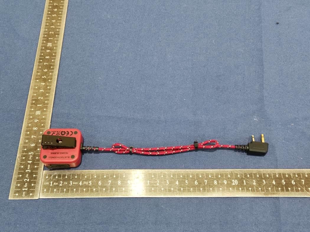
WYQDGL01
Sep 27, 2022Bluetooth Dongle
Equipment Class
DSS - Part 15 Spread Spectrum Transmitter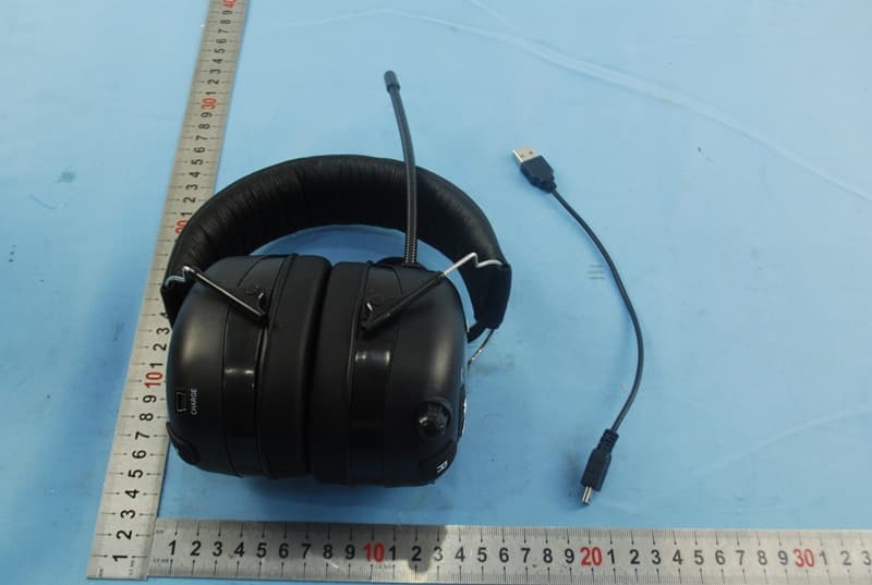
WYQ-BTHP5S
Sep 25, 2014Professional AM/FM Radio with BT and Aux-in Jack
Equipment Class
DSS - Part 15 Spread Spectrum Transmitter