X34CDT909MFWireless Remote Control
Energy Technology Laboratories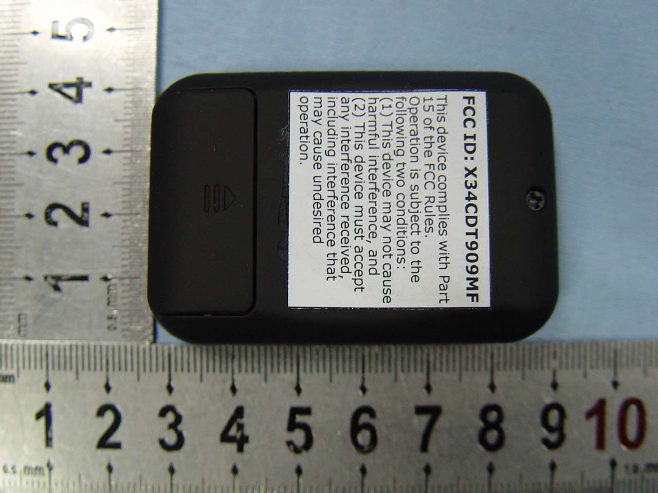
Click to zoom
Application Details
- Equipment Class
- DSC - Part 15 Security/Remote Control Transmitter
- Date of Grant
- Jan 12, 2010
- Application Purpose
- Original Equipment
- Date of Application
- Jan 12, 2010
- Equipment Note
- Wireless Remote Control
- Frequency Range
- 433.90000000 - 433.90000000
- Country
- United States
Documents & Files
Document Text
Text extracted from the exhibit documents filed with the FCC. Open a document above to read the original.
Users Manual
Wireless remote control User Manual 1. Set the user password 1) Using the remote control enter the initial password, enter the password when you press a button for each of its green LED flashes once said that the effective input state. 2) Long press "1 / 2" button 3 seconds until the green long-on, indicate the password to enter the correct change password state, under the red light flashes 3 times that password is invalid and can not change your password. 3) Enter the new password, click "#/*" key to confirm the green light flashes 3 times, indicate password change successful. 4) Re-enter new password, press "#/*" key to confirm, enter the green light flashes 3 times, after the correct password to complete changes 2. Open the door 1) enter your password by press button of remote control 2) "#/*" Button and then click launch, the red indicator light 1 second that was successfully launched. The receiver receiving the signal sent two "beep" sound, while PRC-ray tube so that the door automatically open 3. Wrong password 1) If user enters the wrong password, the red light in the remote control will flash 3 times. FCC STATEMENT 1. This device complies with Part 15 of the FCC Rules. Operation is subject to the following two conditions: (1) This device may not cause harmful interference, and (2) This device must accept any interference received, including interference that may cause undesired operation. 2. Changes or modifications not expressly approved by the party responsible for compliance could void the user’s authority to operate the equipment. NOTE: This equipment has been tested and found to comply with the limits for a Class B digital device, pursuant to Part 15 of the FCC Rules. These limits are designed to provide reasonable protection against harmful interference in a residential installation. This equipment generates, uses and can radiate radio frequency energy and, if not installed and used in accordance with the instructions, may cause harmful interference to radio communications. However, there is no guarantee that interference will not occur in a particular installation. If this equipment does cause harmful interference to radio or television reception, which can be determined by turning the equipment off and on, the user is encouraged to try to correct the interference by one or more of the following measures: -- Reorient or relocate the receiving antenna. -- Increase the separation between the equipment and receiver. -- Connect the equipment into an outlet on a circuit different from that to which the receiver is connected. -- Consult the dealer or an experienced radio/TV technician for help.
Block Diagram
Applicant:Energy Technology Laboratories FCC ID:X34CDT909MF Block Diagram Antenna (TX: 433.92MHz) Modulating amplifier XTAL OSC 433.92MHz MCU (U2) Encoding memory (U3) Press Button Indicator LED Voltage regulator (U1) DC 12V
ID Label/Location Info
FCC Certification Label Sample
ID Label/Location Info
FCC Certification Label Location Sample Label location
Internal Photos
Antenna
Operational Description
Applicant:Energy Technology Laboratories FCC ID:X34CDT909MF Operation Description U1 is voltage regulator IC, which make the voltage reach 3V to support the whole circuit. U2 is MCU, during press the button, U2 produce encoded signal. U3 is data encoding memory. U4, SAW, C7, L3 make up of modulating amplifier. RF signal send out through the antenna Antenna is formed by a copper trace on the PCB. Common grounding on PCB is not connected to real external ground. Power supply is DC 12V by a “23A” battery.
Schematics
Antenna
Test Report
Page 1 of 31 FCC ID: X34CDT909MF ACCURATE TECHNOLOGY CO. LTD REPORT NO. ATE20092654 APPLICATION CERTIFICATION On Behalf of Energy Technology Laboratories Wireless remote control Model No.: CDT909MF FCC ID: X34CDT909MF Prepared for : Energy Technology Laboratories Address : 976 united circle, Sparks, NV 89431, US Prepared by : ACCURATE TECHNOLOGY CO. LTD Address : F1, Bldg. A, Changyuan New Material Port, Keyuan Rd. Science & Industry Park, Nanshan, Shenzhen, Guangdong P.R. China Tel: (0755) 26503290 Fax: (0755) 26503396 Report Number : ATE20092654 Date of Test : December 28, 2009 - January 8, 2010 Date of Report : January 8, 2010 Page 2 of 31 FCC ID: X34CDT909MF ACCURATE TECHNOLOGY CO. LTD REPORT NO. ATE20092654 TABLE OF CONTENTS Description Page Test Report Certification 1. GENERAL INFORMATION..................................................................................................... 4 1.1. Description of Device (EUT)...............................................................................................................4 1.2. Description of Test Facility.................................................................................................................5 1.3. Measurement Uncertainty....................................................................................................................5 2. MEASURING DEVICE AND TEST EQUIPMENT................................................................ 6 3. SUMMARY OF TEST RESULTS.............................................................................................. 7 4. THE FIELD STRENGTH OF RADIATION EMISSION....................................................... 8 4.1. Block Diagram of Test Setup...............................................................................................................8 4.2. The Field Strength of Radiation Emission Measurement Limits.........................................................9 4.3. Configuration of EUT on Measurement..............................................................................................9 4.4. Operating Condition of EUT...............................................................................................................9 4.5. Test Procedure...................................................................................................................................10 4.6. The Field Strength of Radiation Emission Measurement Results.....................................................11 5. 20DB OCCUPIED BANDWIDTH........................................................................................... 13 5.1. Block Diagram of Test Setup.............................................................................................................13 5.2. The Bandwidth of Emission Limit According To FCC Part 15 Section 15.231(c)...........................13 5.3. EUT Configuration on Measurement................................................................................................14 5.4. Operating Condition of EUT.............................................................................................................14 5.5. Test Procedure...................................................................................................................................14 5.6. Measurement Result..........................................................................................................................15 6. RELEASE TIME MEASUREMENT....................................................................................... 16 6.1. Block Diagram of Test Setup.............................................................................................................16 6.2. Release Time Measurement According To FCC Part 15 Section 15.231(a).....................................16 6.3. EUT Configuration on Measurement................................................................................................17 6.4. Operating Condition of EUT.............................................................................................................17 6.5. Test Procedure...................................................................................................................................17 6.6. Measurement Result..........................................................................................................................18 7. AVERAGE FACTOR MEASUREMENT............................................................................... 19 7.1. Block Diagram of Test Setup.............................................................................................................19 7.2. Average factor Measurement according to ANSI 63.4: 2003............................................................19 7.3. EUT Configuration on Measurement................................................................................................20 7.4. Operating Condition of EUT.............................................................................................................20 7.5. Test Procedure...................................................................................................................................20 7.6. Measurement Result..........................................................................................................................21 APPENDIX I ( TEST CURVES) (9 pages) Page 3 of 31 Test Report Certification Applicant : Energy Technology Laboratories Manufacturer : ShenZhen ChenDaZhiKe Electronic Co., Ltd. EUT Description : Wireless remote control (A) MODEL NO.: CDT909MF (B) SERIAL NO.: N/A (C) POWER SUPPLY: 12V DC (“23A” batteries 1×) Measurement Procedure Used: FCC Rules and Regulations Part 15 Subpart C Section 15.231 ANSI 63.4: 2003 The device described above is tested by ACCURATE TECHNOLOGY CO. LTD to determine the maximum emission levels emanating from the device. The maximum emission levels are compared to the FCC Part 15 Subpart C Section 15.231. Th…
Text truncated - open the document above for the full version.
Test Setup Photos
Radiated emissions test < 1GHz Radiated emissions test > 1GHz
Contact Information
Applicant
Brad Robbins(Product Coordinator)
Test Firm
Accurate Technology Co., Ltd.Sean Liu
Technical Specifications
| # | Rule Parts | Frequency Range | Power Output |
|---|---|---|---|
| 1 | 15.231 | 433.9 MHz - 433.9 MHz | - |
Other Applications from Energy Technology Laboratories

X34-YL13-5
Jan 12, 2014remote controller
Equipment Class
DSC - Part 15 Security/Remote Control Transmitter