X3HCP100GLBS
CUMAN Co., Ltd.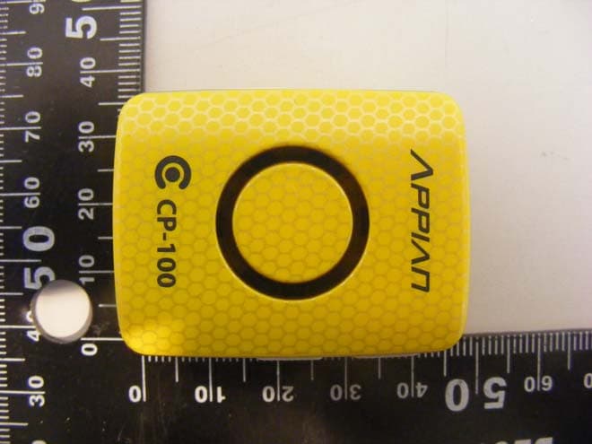
Click to zoom
Application Details
- Equipment Class
- PCT - PCS Licensed Transmitter worn on body
- Date of Grant
- Apr 12, 2010
- Application Purpose
- Original Equipment
- Date of Application
- Apr 12, 2010
- Equipment Note
- LBS
- Frequency Range
- 1850.20000000 - 1909.80000000
- Company
- CUMAN Co., Ltd.
- Country
- South Korea
Documents & Files
Document Text
Text extracted from the exhibit documents filed with the FCC. Open a document above to read the original.
Users Manual
CONFIDENTIALCONFIDENTIAL CONFIDENTIAL CP-100G 1) Device and Accessories CP-100G Owner’s Manual 2 USB Cable Waterproof Case for Pets (Option) USB Recharger (Option) I. Getting to Know Your GPS Personal Tracker CONFIDENTIAL CONFIDENTIAL CP-100G I. Getting to Know Your GPS Personal Tracker 2) Introduction to CP-100G 3 Part Feature ⓐLED Windo wDisplaying status of Device ⓑSIM Card Slot Inserting GSM SIM Card ⓒUSB SlotProgram Update by USB Cable Battery Recharge by USB Cable ⓓReset Button Reset your Device ⓔPower Button Turn ON & OFF ⓕSOS Button Send SOS Message CONFIDENTIAL CONFIDENTIAL CP-100G 3) Charging the Battery New battery built in CP-100G is shipped partially charged. Before you use CP-100G, you need to charge the battery as described below. Some batteries are performing the best after several full charge/discharge cycles. Before you start charging battery, make sure CP-100G is power off. I. Getting to Know Your GPS Personal Tracker RED LED shall be on when battery level is low USB Cable LED indicator for charging status “ How to charge the battery” 1.Power off ( Press and hold ‘Power Button’for 5 seconds) 2.Connect CP-100G with your PC or USB Recharger using USB Cable. 3.It shall take 4~5 hours to fully recharge battery but it might be a little different depending on the battery condition. 4.LED indicator on the top side of USB Cable connector shall be turned on RED while charging battery, and it shall be changed to GREEN when battery is fully charged. CUMAN recommend to keep charging for 4 hours at least although LED indicator changed to GREEN a couple of hours after you start charging. 4 CONFIDENTIAL CONFIDENTIAL CP-100G 4) Inserting SIM Card You should make sure CP-100G is POWER OFF before you insert SIM card. If you insert SIM card while CP-100G is POWER ON, it might be not properly working, and in this case, you may remove SIM card from CP-100G and press reset button. Open the rubber cover at the right side and slide the SIM card into the SIM Card Slot beneath USB slot. * Note: CP-100G shall not work at all without SIM card •Slide SIM card into slot by correct direction as shown above. I. Getting to Know Your GPS Personal Tracker Open the rubber cover 5 CONFIDENTIAL CONFIDENTIAL CP-100G II. Starting Up 1) Features of Location Tracking Device, CP-100G CP-100G was designed for 2 kinds of Operation Modes, Person to Person (P2P) and Operator to Customer (B2C). This manual shall introduce the features of CP-100G by P2P mode only, and you can track your kids, pets and assets by SMS of pre-assigned simple command sets, using your mobile phone or Smartphone or PC. A. Commands to Set Up CP-100G for ..... a). The Control Phone number to receive status of CP-100G b). The time period for location report c). The area to allow moving zone d). The local time where you are using your device by adjusting from GMT B. Reporting for ..... a). The Location periodically using GPS b). The Location immediately using GPS c). Zone out as being beyond allowed zone that you can set up by yourself d). My Zone Out as being beyond the point set up by yourself e). SOS / Emergency f). Battery Warning / Low Battery 6 CONFIDENTIAL CONFIDENTIAL CP-100G II. Starting Up 2) Turning your device ON and OFF Low battery IndicationLED GSM Error Indication LED Operation IndicationLED A. Power ON Press and hold ‘Power Button’for 5 seconds, and then, each LED shall be turned on and blink 3 times by one after another. You can release Power Button once LED starts blinking. B. Power OFF Press and hold ‘Power Button’for 5 seconds, and you shall see all the LED lights shall blink 3 times at the same time. You can release Power Button once LED starts blinking. 7 CONFIDENTIAL CONFIDENTIAL CP-100G II. Starting Up 3) Battery Capacity The Battery capacity shall depend on operating conditions including mobile network, GPS level and/or reporting period etc. By default, CP-100G is set to wake up every 30 minutes to fix GPS and check up GSM network, automatically updating for the most ideal operating condition. Below table can be reference when you set up Periodic Report described in page 12 of this manual. Reporting PeriodStandby & WorkingTimeRemarks 1 Minute7 Hours Reporting location every minute 10 Minutes35 Hours Reporting location every 10 minutes 30 Minutes70 Hours Reporting location every 30 minutes 1 Hour80 Hours Reporting location every hour 2 Hours90 Hours Reporting location every 2 hours 4 Hours100 Hours Reporting location every 4 hours 23 Hours110 Hours Reporting location every 23 hours 8 (The above standby and working time was measured under normal condition of mobile network and GPS) CONFIDENTIAL CONFIDENTIAL CP-100G A. Some carriers’ (Mobile Phone Service companies) SIM Card may require PIN CODE before you start using for the first time or anytime when the power of your device is turned on. B. Your Device, CP-100G can only work with SIM Card free from PIN CODE restriction, and you may check up the SIM Card before you insert into CP-100G if it requires PIN CODE. 1. Insert SIM Card into your mobile phone to see if PIN CODE is required. 2. If PIN CODE is required by carriers, you may input PIN CODE given by carriers to activate SIM Card and set PIN CODE function to be “DISABLE“ or “OFF“. It is various depending on mobile phone manufacturers and models, but you may usually find out PIN CODE function control in the menu of Phone Setting. C. You can also check up if SIM card in CP-100G can be workable using CP-100G. 1. Yellow LED shall be turned on if PIN CODE is required or SIM Card is the defected. 2. You can use SIM Card if there is no yellow LED turned on. D.First GPS Fix of your device, CP-100G When you start using CP-100G for the first time, CUMAN strongly recommend for you to keep CP-100G out in the widely open sky area for about 10 minutes at least to fix GPS for the first time. Once CP-100G fix initial GPS data, it shall be working as fast as “Hot Start Condition” whenever it is requi red to repo rt location information…
Text truncated - open the document above for the full version.
External Photos
Model : CP-100G External photos of EUT Model : CP-100G Front view of EUT Rear view of EUT Model : CP-100G Top view of EUT Bottom view of EUT Model : CP-100G Side view of EUT
ID Label/Location Info
FCC Label 1. FCC Label Drawing 2. FCC Label Location CUMAN Co., Ltd. Model : CP-100G FCC ID : X3HCP100G Made in Korea
Internal Photos
Model : CP-100G Internal photos of EUT Model : CP-100G Top view of Main PCB Bottom view of Main PCB Model : CP-100G Top view of RF PCB Bottom view of RF PCB Model : CP-100G Antenna
Parts List/Tune Up Info
. Copyright © 2010 CUMAN Co., Ltd CP-100G Tune-up Procedure Version 1.1.0 Remark Author Woo Jae Il Department CUMAN co Ltd LBS part Issue Date 2010-04-07 Version 1.1.0 Etc All rights reserved. Reproduction, use or disclosure of this document without written approval of Cuman authority is strictly forbidden. Cuman Ltd.co. LBS part CONFIDENTIAL Page 2/6 1. Test Configuration of Equipment under Test The EUT has been tested under continuous transmitting mode All tests are performed at low channel, Middle channel, High channel During all testing, EUT is in link mode with Network Equipment (Wireless Communications Test set 8960) at Maximum power level 2. Set-up Equipment z Equipment : E5515C(8960, Firmware : 1968A) , PC , Test unit GPIB Cable RF Cable Power supply PC CP-100G Fig 1 Setting up connection All rights reserved. Reproduction, use or disclosure of this document without written approval of Cuman authority is strictly forbidden. Cuman Ltd.co. LBS part CONFIDENTIAL Page 3/6 3. Setting the tune-up program 3-1. Run the MFC application program for RF calibration. -Check Item: Power Calibration, CDAC Calibration, AFCDAC Calibration, Rx Board Gain 3-2. Click “Config” button. All rights reserved. Reproduction, use or disclosure of this document without written approval of Cuman authority is strictly forbidden. Cuman Ltd.co. LBS part CONFIDENTIAL Page 4/6 3-3. You can see as shown below. 3-4. Set up your configurations. - Communication Port - Baud rate: 1152000 - Cable Loss GSM850: 0.8dB, PCS1900: 1.0dB All rights reserved. Reproduction, use or disclosure of this document without written approval of Cuman authority is strictly forbidden. Cuman Ltd.co. LBS part CONFIDENTIAL Page 5/6 3-4. Select your band and channel. (If you don’t add test item anymore, press OK button.) 3-4. Run “Auto Calibration”. All rights reserved. Reproduction, use or disclosure of this document without written approval of Cuman authority is strictly forbidden. Cuman Ltd.co. LBS part CONFIDENTIAL Page 6/6 4. Target of Output Power 4-1. GSM850 Band 128channel, 178channel, 251channel: 30.2dBm 4-2. PCS1900 Band 512channel, 601channel, 810channel: 28.5dBm
RF Exposure Info
Report File No. : F690501/RF-SAR001857-A1 Date of Issue : 2010-04-02 Page : 2 / 67 Contents 1. General Information 1.1 Testing Laboratory........................................................................................... 3 1.2 Details of Applicant.......................................................................................... 3 1.3 Version of Report............................................................................................. 3 1.4 Description of EUT(s)....................................................................................... 3 1.5 Test Environment............................................................................................. 4 1.6 Operation description........................................................................................ 4 1.7 Evaluation procedures....................................................................................... 5 1.8 The SAR Measurement System............................................................................ 6 1.9 System Components.......................................................................................... 8 1.10 SAR System Verification.................................................................................... 9 1.11 Tissue Simulant Fluid for the Frequency Band.......................................................... 11 1.12 Test Standards and Limits.................................................................................. 12 2. Instruments List.................................................................................... 14 3. Summary of Results................................................................................ 15 APPENDIX A. Photographs of EUT & EUT’s Test Setup B. DASY4 SAR Report C. Uncertainty Analysis D. Calibration certificate Report File No. : F690501/RF-SAR001857-A1 Date of Issue : 2010-04-02 Page : 3 / 67 1. General Information 1.1 Testing Laboratory SGS Testing Korea Co., Ltd. Wireless Div. 2FL, 18-34, Sanbon-dong, Gunpo-si, Gyeonggi-do, Korea 435-040 Telephone : +82 +31 428 5700 FAX : +82 +31 427 2371 Homepage : www.kr.sgs.com.ee 1.2 Details of Manufacturer Manufacturer : CUMAN Co., Ltd. Address : 2F, Dongsung Build. 1229-11 Gaepo-dong, Gangnam-gu, Seoul, Korea Contact Person : WOO, JAE IL Phone No. : 82-70-8220-6951 Fax No. : 82-2-574-6639 1.3 Version of Report Version Number Date Revision 00 2010-03-17 Initial issue 01 2010-04-02 Revision 01 1.4 Description of EUT(s) EUT Type : LBS Model : CP-100G Serial Number : N/A Mode of Operation : GSM(GPRS)850, GSM(GPRS)1900 Body worn Accessory : None Tx Frequency Range : 824.2 MHz ~ 848.8 MHz (GSM850) 1850.2 MHz ~ 1909.8 MHz (GSM1900) Conducted Max Power : 30.2 dBm(GSM850), 28.5 dBm(GSM1900) Battery Type : 3.7 V (Li-Polymer Battery) Report File No. : F690501/RF-SAR001857-A1 Date of Issue : 2010-04-02 Page : 4 / 67 1.5 Test Environment Ambient temperature : 21 ° C - 23 ° C Tissue Simulating Liquid : 21 ° C - 23 ° C Relative Humidity : 40 % - 60 % 1.6 Operation Configuration The device was controlled by using a Mobile Test Unit (CMU200). Communication between the device and the tester was established by air link. Measurements were performed on the lowest, middle and highest channels of the operating band. The device was set to maximum power level during all tests and at the beginning of each test the battery was fully charged. The DASY4 system measures power drift during SAR testing by comparing e-field in the same location at the beginning and at the end of measurement. Report File No. : F690501/RF-SAR001857-A1 Date of Issue : 2010-04-02 Page : 5 / 67 1.7 EVALUATION PROCEDURES - Power Reference Measurement Procedures The Power Reference Measurement and Power Drift Measurements are for monitoring the power drift of the device under test in the batch process. The Minimum distance of probe sensors to surface determines the closest measurement point to phantom surface. The minimum distance of probe sensors to surface is 4 mm. This distance cannot be smaller than the Distance of sensor calibration points to probe tip as defined in the probe properties (for example, 2.7 mm for an ET3DV6 probe type). - The entire evaluation of the spatial peak values is performed within the Post-processing engine (SEMCAD). The system always gives the maximum values for the 1 g and 10 g cubes. The algorithm to find the cube with highest averaged SAR is divided into the following stages: 1. The extraction of the measured data (grid and values) from the Zoom Scan. 2. The calculation of the SAR value at every measurement point based on all stored data (A/D values and measurement parameters) 3. The generation of a high-resolution mesh within the measured volume 4. The interpolation of all measured values from the measurement grid to the high-resolution grid 5. The extrapolation of the entire 3-D field distribution to the phantom surface over the distance from sensor to surface 6. The calculation of the averaged SAR within masses of 1 g and 10 g. The probe is calibrated at the center of the dipole sensors that is located 1 to 2.7 mm away from the probe tip. During measurements, the probe stops shortly above the phantom surface, depending on the probe and the surface detecting system. Both distances are included as parameters in the probe configuration file. The software always knows exactly how far away the measured point is from the surface. As the probe cannot directly measure at the surface, the values between the deepest measured point and the surface must be extrapolated. The angle between the probe axis and the surface normal line is less than 30 degree. In the Area Scan, the gradient of the interpolation function is evaluated to find all the extreme of the SAR distribution. The uncertainty on the locations of the extreme is less than 1/20 of the grid size. Only local maximum within –2 dB of the global maximum are searched and passed for the Cube Scan measurement. In the Cube Scan, the interpolatio…
Text truncated - open the document above for the full version.
Test Report
Report Number : F690501/RF-RTL003660-1 Page: 1 of 30 The results shown in this test report refer only to the sample(s) tested unless otherwise stated. This test report cannot be reproduced, except in full, without prior written permission of the Company. SGS Testing Korea Co., Ltd. 18-34, Sanbon-dong, Gunpo-si, Gyeonggi-do, Korea, 435-040 Tel. +82 31 428 5700 / Fax. +82 31 427 2371 www.electrolab.kr.sgs.com TEST REPORT of FCC Part 22 Subpart H and Part 24 Subpart E FCC ID : X3HCP100G Equipment Under Test : LBS Model Name : CP-100G Serial No. : N/A Applicant : CUMAN Co., Ltd. Manufacturer : CUMAN Co., Ltd. Date of Test(s) : 2010-02-18 ~ 2010-03-15 Date of Issue : 2010-04-02 In the configuration tested, the EUT complied with the standards specified above. Te s t e d B y : Date 2010-04-02 Grant Lee Approved By Date 2010-04-02 Charles Kim Report Number : F690501/RF-RTL003660-1 Page: 2 of 30 The results shown in this test report refer only to the sample(s) tested unless otherwise stated. This test report cannot be reproduced, except in full, without prior written permission of the Company. SGS Testing Korea Co., Ltd. 18-34, Sanbon-dong, Gunpo-si, Gyeonggi-do, Korea, 435-040 Tel. +82 31 428 5700 / Fax. +82 31 427 2371 www.electrolab.kr.sgs.com INDEX TABLE OF CONTENTS Page 1. General Information -----------------------------------------------------------------------------3 2. RF radiated output power & spurious radiated emission --------------------------------7 3. Conducted Output Power -----------------------------------------------------------------------13 4. Occupied Bandwidth 99 % ---------------------------------------------------------------------15 5. Spurious Emissions At Antenna Terminal---------------------------------------------------20 6. Band Edge ------------------------------------------------------------------------------------------25 7. Frequency Stability ------------------------------------------------------------------------------ 28 Report Number : F690501/RF-RTL003660-1 Page: 3 of 30 The results shown in this test report refer only to the sample(s) tested unless otherwise stated. This test report cannot be reproduced, except in full, without prior written permission of the Company. SGS Testing Korea Co., Ltd. 18-34, Sanbon-dong, Gunpo-si, Gyeonggi-do, Korea, 435-040 Tel. +82 31 428 5700 / Fax. +82 31 427 2371 www.electrolab.kr.sgs.com 1. General information 1.1. Testing laboratory SGS Testing Korea Co., Ltd. - 705, Dongchun-Dong Sooji-Gu, Yongin-Shi, Kyungki-Do, South Korea . - Wireless Div. 2FL, 18-34, Sanbon-dong, Gunpo-si, Gyeonggi-do, Korea 435-040 www.electrolab.kr.sgs.com Telephone : +82 +31 428 5700 FAX : +82 +31 427 2371 1.2. Details of applicant Applicant : CUMAN Co., Ltd. Address : 2F, Dongsung build. 1229-11 Gaepo-Dong, Gangnam-Gu, Seoul, Korea Contact Person : WOO, JAE IL Phone No. : +82 +70 8220 6951 1.3. Description of EUT Kind of Product LBS Model Name CP-100G Serial Number N/A Power Supply DC 3.7 V (Li-polymer Battery) Rated Power GSM850 : 30.2 dBm GSM1900 : 28.5 dBm Frequency Range GSM850 : 824.2 MHz ~ 848.8 MHz GSM1900 : 1850.2 MHz ~ 1909.8 MHz Number of Channels GSM850 : 125 GSM1900 : 300 Antenna gain GSM850 : 6.2㏈i GSM1900 : 3.8 ㏈i Antenna type Fix type Class of GPRS Class 10 Report Number : F690501/RF-RTL003660-1 Page: 4 of 30 The results shown in this test report refer only to the sample(s) tested unless otherwise stated. This test report cannot be reproduced, except in full, without prior written permission of the Company. SGS Testing Korea Co., Ltd. 18-34, Sanbon-dong, Gunpo-si, Gyeonggi-do, Korea, 435-040 Tel. +82 31 428 5700 / Fax. +82 31 427 2371 www.electrolab.kr.sgs.com 1.4. Description of test mode 1.4.1 GSM Band Band Mode Frequency (MHz) Average output power (dBm) 824.2 30.1 836.6 30.2 GSM Voice 848.8 30.1 824.2 30.0 836.6 30.1 1 Tx Slot 848.8 30.1 824.2 29.9 836.6 30.0 GSM 850 GPRS 2 Tx Slot 848.8 30.0 1850.2 28.5 1880.0 28.3 GSM Voice 1909.8 28.1 1850.2 28.5 1880.0 28.2 1 Tx Slot 1909.8 28.1 1850.2 28.4 1880.0 28.2 GSM 1900 GPRS 2 Tx Slot 1909.8 28.1 GSM (850 / 1900) We found out the test mode with the highest power level after we analyze all the data rates. So we chose GSM voice mode (worst case) as a representative. Report Number : F690501/RF-RTL003660-1 Page: 5 of 30 The results shown in this test report refer only to the sample(s) tested unless otherwise stated. This test report cannot be reproduced, except in full, without prior written permission of the Company. SGS Testing Korea Co., Ltd. 18-34, Sanbon-dong, Gunpo-si, Gyeonggi-do, Korea, 435-040 Tel. +82 31 428 5700 / Fax. +82 31 427 2371 www.electrolab.kr.sgs.com 1.5. Test equipment list Equipment Manufacturer Model Cal Due. Signal Generator Agilent E4438C Mar. 31, 2011 Signal Generator Rohde & Schwarz SMR40 Sep. 25, 2010 Spectrum Analyzer Rohde & Schwarz FSV30 May. 15, 2010 Spectrum Analyzer Agilent E4440A Mar. 31, 2011 Signal Generator Rohde & Schwarz SMR40 Sep. 25, 2010 Mobile Test Unit Agilent E5515C Mar. 31, 2011 Directional Coupler Narda 4226-20 Jan. 07, 2011 High Pass Filter Wainwright WHK3.0/18G-10SS Sep. 29, 2010 Band Reject Filter Wainwright WRCG824/849-814/85960/10SS Apr. 01, 2011 DC power Supply Agilent U8002A Jan. 06, 2011 Preamplifier Empower RF Systems,Inc2002-BBS2C4AEL Mar. 31, 2011 Preamplifier Rohde & Schwarz 8449B Mar. 31, 2011 Test Receiver R & S ESU26 Apr. 21, 2010 Bilog Antenna SCHWARZBECK MESSELEKTRONIK VULB9163 Jul. 22, 2010 Horn Antenna Rohde & Schwarz HF 906 Oct. 08, 2011 Horn Antenna SCHWARZBECK BBH 9120D Nov. 09, 2011 Dipole Antenna VHAP/UHAP 975/958 Oct. 10, 2011 Antenna Master EMCO 1050 N.C.R Turn Table Daeil EMC DI-1500 N.C.R Anechoic Chamber SY Corporation L × W × H (9.6 m × 6.4 m × 6.6 m) Jan. 27, 2011 Report Number : F690501/RF-RTL003660-1 Page: 6 of 30 The results shown in this test report refer only to the sample(s) tested unless otherwise stated. This test report cannot be reproduced, except in full, without prior written permission of the Co…
Text truncated - open the document above for the full version.
Test Setup Photos
Test setup photo of EUT A. Photo of Effective Radiated Power & Spurious Emission Test
Contact Information
Applicant
JAE IL WOO
Test Firm
SGS Korea Co., Ltd.Elan Lee
Technical Specifications
| # | Rule Parts | Frequency Range | Power Output | Emission | Tolerance |
|---|---|---|---|---|---|
| 2 | 24E | 1.85 GHz - 1.91 GHz | 352.00 mW | 311KGXW | 2.5 ppm |