X4FWR-V18WIRELESS MICROPHONE
WHANSIL (ENPING) ELECTRONIC CO., LTD.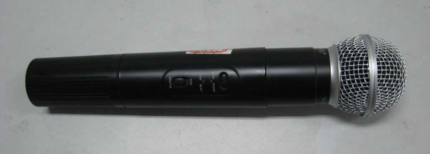
Click to zoom
Application Details
- Equipment Class
- TBF - Licensed Broadcast Transmitter Held to Face
- Date of Grant
- Jan 20, 2010
- Application Purpose
- Original Equipment
- Date of Application
- Jan 19, 2010
- Equipment Note
- WIRELESS MICROPHONE
- Frequency Range
- 174.00000000 - 216.00000000
- Country
- China
Documents & Files
Document Text
Text extracted from the exhibit documents filed with the FCC. Open a document above to read the original.
Block Diagram
PDF 文件以 "pdfFactory Pro" 试用版创建 www.pdffactory.com
Cover Letter(s)
Jan-15-2010 Dear TCB Reviewer, Thank you for cooperation. I would like to submit FCC application of. WHANSIL(ENPING) ELECTRONIC CO.,LTD (FCC ID: X4FWR-V18, model: WR-V18) to you today. Best Regards, Guangzhou Huesent Testing Service Co., Ltd. Jerry Chen Deputy General Manager
External Photos
External Photographs of FCCID: X4FWR-V18
ID Label/Location Info
FCC ID Label Sample FCC ID: X4FWR-V18 This device complies with Part 74 of the FCC Rules.
ID Label/Location Info
FCCID: X4FWR-V18 Label Location
Internal Photos
Internal Photographs FCCID: X4FWR-V18
Operational Description
Wireless microphone circuit description of WR-V18 AUDIO CIRCUIT The audio signal is injected via the microphone sensor into the audio circuit composed of the op amp IC1 4558, & compandor IC2 UTC571N. The signal is compressed via the compandor circuit at a 2:1 ratio and is pre-emphasized by U1. The level of the output signal is controlled by the variable 10k resistor. MODULATOR CIRCUIT The modulator circuit is a direct FM type built around the local oscillator controlled by Crystal Y1, Q1 (Type T33), variable capacitance diode VD1, IFT 1~3, and Cap. The modulated output from the oscillator is sent to the RF pre-amp. RF PRE-AMPLIFIER & FINAL AMPLIFIER 3 transistor amplifier stages, using Q2~4 (T33x2, 9018) transistors, culminating with a normal transmitter output of <1mW. The output filter comprised of 4 Caps (1p, 22p x 2, 1000p), VC1 (0-20p), 2 L (3T, 4T) suppresses the output harmonics and matches the output to the integrate antenna. POWER SUPPLY. Up the input voltage by Q7-8(4091, 2198), and steadied by U1 78L05. with a voltage detector consist by Q5-6 and LED.
Parts List/Tune Up Info
BOM TX nametypeqtynametypeqty LED 2S18151 102P2KSP101 103P6TX SWITCH3061 200P2 crystal13.9MHz 1 502P1 10K VR10k ohm 1 0.5P2 K-22-D PCB 1 150P13*4.5T*0.64 15P33*6.5T*0.61 20P2231 22P1261 30P1 LED2*5 GREEN 1 33P2 6P1 MIC D271 CONDUCTOR 3.3UH2 *10U/10V5 *1U/10V1 *2.2U/10V4 2201 100K1 10K6 15K1 1K1 1.5K1 220K1 22K2 2.2K1 33K1 3.3K1 47K1 47Ω 1 4.7K1 82K1 1N41481 1S26381 78L051 SP311011 90182 C17402 Transistor E-CAP. RESISTANCE diode IC transistor Ceramic Cap. COIL IFT
Test Report
FCCID: X4FWR-V18 Report Number: HST200912-2416-FCC Page 1 of 21 Test Report Applicant: WHANSIL(ENPING) ELECTRONIC CO., LTD. Address of Applicant: No.23 Ping Kang Street, Enping City, Guangdong, China. Equipment Under Test (EUT): EUT Name: Packaged Microphone Model No.: WR-V18, WR-118, WR-138, WR-133, WR-1060, WR-1030, WR-78, WR-208, WR-2.9, WR-1000, WR-8888, WR-680, WR-980, WR-88, WR-990, WR-66, WR-998, WR-668 Trade Mark: N A Serial No.: Not supplied by client Standards: FCC PART15 SUBPART C: 2008 Date of Receipt: Nov. 10, 2009 Date of Test: Dec. 14 to 16, 2009 Date of Issue: Dec. 20, 2009 Test Result : PASS* * In the configuration tested, the EUT complied with the standards specified above. Authorized Signature: Henly Xie / Manager This report refers to the General Conditions for Inspection and Testing Services, printed overleaf This report details the results of the testing carried out on one sample. The results contained in this test report do not relate to other samples of the same product. The manufacturer should ensure that all products in series production are in conformity with the product sample detailed in this report. This report may only be reproduced and distributed in full. If the product in this report is used in any configuration other than that detailed in the report, the manufacturer must ensure the new system complies with all relevant standards. The report must not be used by the client to claim product certification, approval, or endorsement by NVLAP, NIST, or any agency of the federal government. All test results in this report can be traceable to National or International Standards. The test report prepare by: Guangzhou Huesent Testing Service Co.,Ltd. Self-ordained 68# courtyard, No.91, Dongguanzhuang Road,Guangzhou,China. Tel: 86-20-28263298 Fax: 86-20-28263237 http://www.hst.org.cn E-mail:[email protected] Report Number: HST200912-2416-FCC Page 2 of 21 CONTENTS 1 Test Summary..................................................................................................................3 2 General Information.........................................................................................................4 2.1 Client Information .......................................................................................................4 2.2 General Description of E.U.T. ....................................................................................4 2.3 Details of E.U.T. .........................................................................................................4 2.4 Description of Support Units ......................................................................................4 2.5 Standards Applicable for Testing ...............................................................................4 2.6 Test Location .............................................................................................................5 2.7 Deviation from Standards...........................................................................................5 2.8 Abnormalities from Standard Conditions....................................................................5 3 Equipments Used during Test..........................................................................................6 4 Test Results.....................................................................................................................7 4.1 E.U.T. Operation Condition ........................................................................................7 4.2 Test Procedure & Measurement Data........................................................................8 4.2.1 Carrier Radiated Power & Radiated Spurious Emissions ...................................8 4.2.2 Occupied Bandwidth .........................................................................................11 4.2.3 Frequency Stability ...........................................................................................14 4.2.4 Modulation Characteristics................................................................................16 4. Photographs...................................................................................................................19 4.1. Radiated Emission Test Setup .................................................................................19 4.2. EUT Constructional Details ......................................................................................20 Report Number: HST200912-2416-FCC Page 3 of 21 1 Test Summary Test Test RequirementStandard Paragraph Result Carrier Radiated Power FCC Part 2.1046 74.861 e) 1) 174M-216M--50mW PASS Modulation Deviation FCC Part 2.1047 74.861 e) 3) Within 75kHz PASS Frequency Stability FCC Part 2.1055 74.861 e) 4) <0.005% 50 ppm PASS Operating Bandwidth FCC Part 2.1049 c)74.861 e) 5) Within 200kHz PASS Unwanted Radiation FCC Part 2.1049 c)74.861 e) 6) within the mask PASS Radiated Spurious Emission FCC Part 2.1053 74.861 d) 3) < 43+10lgP(W) dB PASS Remark: ♣The EUT has one channel, which is located in the range 174.0M-216.0MHz . Only test result of one samples in 190.1 MHz, 174.2 MHz and 215.8 MHz were recorded in this report. The EUT frequency cannot be adjustable by user. Report Number: HST200912-2416-FCC Page 4 of 21 2 General Information 2.1 Client Information Applicant: WHANSIL(ENPING) ELECTRONIC CO., LTD. Address of Applicant: No.23 Ping Kang Street, Enping City, Guangdong, China. 2.2 General Description of E.U.T. EUT Name: Wireless Microphone Item No.: WR-V18, WR-118, WR-138, WR-133, WR-1060, WR-1030, WR-78, WR-208, WR-2.9, WR-1000, WR-8888, WR-680, WR-980, WR-88, WR-990, WR-66, WR-998, WR-668 All the models listed above were electrical identical to WR-V18, only the difference being the outlook and color. Serial No.: Not supplied by client 2.3 Details of E.U.T. Power Supply: 9Vdc, 1 x 6F22 size Battery Main Function: Wireless microphone system with an associated receiver for transmitting voice. The final amplifier Collector Vo…
Text truncated - open the document above for the full version.
Test Setup Photos
FCC ID: X4FWR-V18 SETUP
Contact Information
Applicant
Fanji Wu(General Manager)
Test Firm
China CEPREI LaboratoryLihui Chen
Technical Specifications
| # | Rule Parts | Frequency Range | Power Output | Emission | Tolerance |
|---|---|---|---|---|---|
| 1 | 74.861 | 174 MHz - 216 MHz | 500.00 µW | 100KF3E | 50.0000000000 ppm |