X4I-VOX1006TOPMobile PC for logistic voice applications
topsystem GmbH
Click to zoom
Application Details
- Equipment Class
- DXT - Part 15 Low Power Transceiver, Rx Verified
- Date of Grant
- May 06, 2010
- Application Purpose
- Original Equipment
- Date of Application
- May 06, 2010
- Equipment Note
- Mobile PC for logistic voice applications
- Frequency Range
- 2412.00000000 - 2462.00000000
- Company
- topsystem GmbH
- Country
- Germany
Documents & Files
Document Text
Text extracted from the exhibit documents filed with the FCC. Open a document above to read the original.
Users Manual
topSPEECH-Lydia ® -PDA User manual VOXter ® WL-BT 1006 topSPEECH-Release 5.x or higher Version: 1.5 Date: 5 th February 2009 User Manual VOXter ® WL-BT 1006 5 th February 2009 topsystem Systemhaus GmbH Page 2 © Copyright 2009 topsystem Systemhaus GmbH This manual is protected by international copyright laws. Unless explicitly permitted by topsystem Systemhaus GmbH in written form, any use, propagation, duplication or reprint - even in extracts – of these documents or their contents will lead to claims of compensation. topsystem Systemhaus GmbH Monnetstraße 24 52146 Würselen Germany Document information: Author: LK Version: 1.5 Date: 5 th February 2009 Document title: ts_5x_User_Manual_VOXter_1_5_eng.doc User Manual VOXter ® WL-BT 1006 5 th February 2009 topsystem Systemhaus GmbH Page 3 Table of Contents 1 Operating the VOXter ® ............................................................................................... 4 1.1 Introduction............................................................................................................ 4 1.2 Overview ............................................................................................................... 4 1.3 Fastening and carrying the VOXter ® during work .................................................. 5 1.4 Connecting the headset ......................................................................................... 5 2 Basic functions of the VOXter ® .................................................................................. 5 2.1 Switching the device on ......................................................................................... 5 2.2 Switching the device off ......................................................................................... 6 2.3 Volume control....................................................................................................... 6 2.4 Acoustic info button ............................................................................................... 6 2.5 Mute switch............................................................................................................ 6 3 Power supply of the VOXter ® ..................................................................................... 8 3.1 Saftey instruction ................................................................................................... 9 3.2 Replacing the battery............................................................................................. 9 3.3 Charging the battery with the VOXter ® ................................................................. 11 4 General Operations with the VOXter ® ..................................................................... 13 4.1 Logging-in for work .............................................................................................. 13 4.2 Logging-off after work .......................................................................................... 14 5 Speech Training with the VOXter ® ........................................................................... 14 5.1 Speech Training with a PDA ................................................................................ 14 5.2 Allowing connection to CoPilot............................................................................. 15 6 Care instructions ...................................................................................................... 15 6.1 Avoid extreme environmental exposure ............................................................... 15 6.2 Avoid shocks or impacts ...................................................................................... 16 7 Technical information about VOXter ® ..................................................................... 16 8 Appendix I - Overview of selection menus ........................................................... 17 User Manual VOXter ® WL-BT 1006 5 th February 2009 topsystem Systemhaus GmbH Page 4 1 Operating the VOXter ® 1.1 Introduction The VOXter ® is a small mobile computer specially optimised for use with speech-guided logistics applications. The VOXter ® is connected to a server via radio network. This server transmits picking order data to the mobile device, which is then forwarded to the picker via speech output. Each finished work step is then confirmed by the picker with a spoken return, which is again translated into data and transmitted back to the server. For communicating with the VOXter ® , the picker is equipped with a headset combining a headphone and a microphone. A constant radio connection between Pocket-PC and server is not necessarily required for the complete picking procedure. This user manual contains all necessary information for operating the VOXter ® . 1.2 Overview The basic functions of the VOXter ® can be accessed with the buttons provided on the front side of the device. In addition to these buttons, a status display is also available here. The following figure shows the basic operating elements of the VOXter ® : Headset jack Up-/down-buttons Status display Rechargeable battery User Manual VOXter ® WL-BT 1006 5 th February 2009 topsystem Systemhaus GmbH Page 5 1.3 Fastening and carrying the VOXter ® during work On the bottom side of the VOXter ® , a clip is attached which is used for fastening the device to a belt. Make sure the device is safely attached in a proper position and cannot move or drop during work. 1.4 Connecting the headset Before you can start working with the VOXter ® , the headset has to be connected. The headset jack is on the top side of the device. Both jack and plug are marked with a red dot. The cable is connected properly when both dots are positioned adjacent to each other. Figure 1: Headset plug and jack Figure 2: Properly connected headset 2 Basic functions of the VOXter ® 2.1 Switching the device on The VOXter ® is switched on by pressing the On/Off switch on the front of the device. The device is booting when the middle …
Text truncated - open the document above for the full version.
ID Label/Location Info
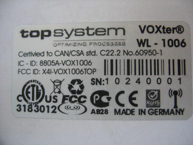
© Copyright 2008 topsystem Systemhaus GmbH This document is protected by copyright. We would like to draw your attention to the fact that we are doing so on the basis that it is a confidential document; that it is not to be disclosed in whole or in part to anybody but the directors and employees of your organization who have a need to know and that it will be used solely for the purpose for which it has been submitted. We trust that you appreciate the commercial reasons for these restrictions. Label VOXter WL BT 1006
RF Exposure Info
This report is for the exclusive use of Intertek's Client and is provided pursuant to the agreement between Intertek and its Client. Intertek's responsibility and liability are limited to the terms and conditions of the agreement. Intertek assumes no liability to any party, other than to the Client in accordance with the agreement, for any loss, expense or damage occasioned by the use of this report. Only the Client is authorized to copy or distribute this report and then only in its entirety. Any use of the Intertek name or one of its marks for the sale or advertisement of the tested material, product or service must first be approved in writing by Intertek. The observations and test results in this report are relevant only to the sample tested. This report by itself does not imply that the material, product, or service is or has ever been under an Intertek certification program. 731 Enterprise Drive Lexington, KY 40510 Telephone: 859-226-1000 Facsimile: 859-226-1040 www.intertek-etlsemko.com TEST REPORT Report Number: 3195932LEX-001 Project Number: 3195932 Evaluation of the topSPEECH-Lydia-PDA Model Number: VOXter 1006 Series WL-BT Tested to the SAR Criteria in FCC OET Bulletin 65, Supplement C (Edition 01-01) RSS-102 Issue 4 For Topsystem Systemhaus GmbH Test Performed by: Test Authorized by: Intertek 731 Enterprise Drive Lexington, KY 40510 Topsystem Systemhaus GmbH Adenauerstr. 20 Europark A2, DE-52146 Wurselen Prepared By:_______________________________Date:____3/26/2009________ Jason Centers, Senior Project Engineer Approved By:______________________________Date:____3/26/2009_________ Bryan Taylor, Team Leader – Engineering 731 Enterprise Drive, Lexington KY 40510 Evaluation For:Topsystem Systemhaus GmbH Model Number: VOXter 1006 Series WL-BT Report Number: 3195932LEX-001 Page 2 of 42 TABLE OF CONTENTS 1.0 DOCUMENT HISTORY ................................................................................................................ 4 2.0 REFERENCES................................................................................................................................. 5 3.0 INTRODUCTION............................................................................................................................ 6 MODIFICATIONS MADE TO TEST SAMPLE.................................................................................................. 6 4.0 TEST SITE DESCRIPTION........................................................................................................... 7 MEASUREMENT EQUIPMENT..................................................................................................................... 8 MEASUREMENT TRACEABILITY................................................................................................................ 8 MEASUREMENT UNCERTAINTY................................................................................................................ 9 5.0 JOB DESCRIPTION ..................................................................................................................... 10 6.0 SYSTEM VERIFICATION .......................................................................................................... 12 SYSTEM VALIDATION.............................................................................................................................. 12 TISSUE SIMULATING LIQUID DESCRIPTION AND VALIDATION............................................................... 14 7.0 EVALUATION PROCEDURES .................................................................................................. 15 TEST POSITIONS: ..................................................................................................................................... 15 REFERENCE POWER MEASUREMENT: .....................................................................................................15 COARSE SCAN: ........................................................................................................................................ 15 ZOOM SCAN: ........................................................................................................................................... 15 DATA EXTRAPOLATION: ......................................................................................................................... 16 REFERENCE POWER MEASUREMENT: .....................................................................................................16 RF AMBIENT ACTIVITY:.......................................................................................................................... 16 8.0 TEST CONFIGURATION............................................................................................................ 17 9.0 CRITERIA...................................................................................................................................... 18 10.0 TABULAR TEST RESULTS .................................................................................................... 19 CONDUCTED POWER MEASUREMENTS................................................................................................... 19 BODY MODE SAR TEST RESULTS........................................................................................................... 19 11.0 GRAPHICAL SAR SCAN RESULTS...................................................................................... 20 12.0 DIPOLE VALIDATION SCANS.............................................................................................. 22 13.0 PROBE CERTIFICATE............................................................................................................ 24 14.0 DIPOLE CERTIFICATE .......................................................................................................... 33 731 Enterprise Drive, Lexington KY 40510 Evaluation For:Topsystem Systemhaus GmbH Model Number: VOXter 1006 Series WL-BT Report Number: 3195932LEX-001 Page 3 of 42 1…
Text truncated - open the document above for the full version.
Test Report
Report Number 3192580BOX-001 Page 1 of 80 EMISSIONS TEST REPORT Report Number: 3192580BOX-001 Project Number: 3192580 Testing performed on the topSPEECH-Lydia-PDA Model: VOXter 1006 Series WL-BT To CFR47 “Telecommunications” FCC Part 15 Subpart C “Intentional Radiators” 15.247 IC RSS-210 “Low Power License Exempt Radiocommunications Devices” Issue 7 June 2007 Annex 8 “Frequency Hopping and Digital Modulation Systems Operating in the Bands 902-928 MHz, 2400-2483.5 MHz, and 5725-5850 MHz” For topsystem Systemhaus GmbH Test Performed by: Test Authorized by: Intertek – ETL SEMKO 70 Codman Hill Road Boxborough, MA 01719 topsystem Systemhaus GmbH Adenauerstr. 20 Europark A2 DE-52146 Würselen Prepared by: Date: November 13, 2009 Nicholas Abbondante Reviewed by: Date: 11/16/09 Jeff Goulet This report is for the exclusive use of Intertek’s Client and is provided pursuant to the agreement between Intertek and its Client. Intertek’s responsibility and liability are limited to the terms and conditions of the agreement. Intertek assumes no liability to any party, other than to the Client in accordance with the agreement, for any loss, expense or damage occasioned by the use of this report. Only the Client is authorized to copy or distribute this report and then only in its entirety. Any use of the Intertek name or one of its marks for the sale or advertisement of the tested material, product or service must first be approved in writing by Intertek. The observations and test results in this report are relevant only to the sample tested. This report by itself does not imply that the material, product, or service is or has ever been under an Intertek certification program. This report must not be used to claim product endorsement by A2LA, NIST nor any other agency of the U.S. Government. Report Number 3192580BOX-001 Page 2 of 80 1.0 Job Description 1.1 Client Information This EUT has been tested at the request of: Company: topsystem Systemhaus GmbH Adenauerstr. 20 Europark A2 DE-52146 Würselen Contact: Herr Jäker Telephone: Fax: Email: +49 (2405) 4670 - 0 +49 (2405) 4670 - 10 [email protected] 1.2 Equipment Under Test Equipment Type: topSPEECH-Lydia-PDA Model Number(s): VOXter 1006 Series WL-BT Serial number(s): 08241172 (Germany), 09240287 (USA) Manufacturer: topsystem Systemhaus GmbH EUT receive date: 10/24/2008(Germany); 09/09/2009(USA) EUT received condition: Prototype in Good Condition Test start date: 12/18/2008(Germany); 10/13/2009(USA) Test end date: 12/18/2008(Germany); 11/09/2009 (USA) 1.3 Test Plan Reference: Tested according to the standards listed, and using the guidance of ANSI C63.4:2003, IC RSS-Gen Issue 2 June 2007, and FCC KDB 558074. 1.4 Test Configuration Fresh 3.7V Battery 1.4.1 Block Diagram VOXter WL-BT Headphones Report Number 3192580BOX-001 Page 3 of 80 1.4.2. Cables: Cable Shielding Connector Length (m) Qty. Headphone Cable Braid Metal/360 0.8 (coiled) 1 1.4.3. Support Equipment: Name: Model No.: Serial No.: Headphones topSPEECH BSVOX9 0809144 1.5 Mode(s) of Operation: During transmitter testing, the EUT was configured to transmit continuously at 80% of maximum power on specific channels low, mid and high channels in WLAN mode. 1.6 Floor Standing Equipment: Applicable:____ Not Applicable:_X _ Report Number 3192580BOX-001 Page 4 of 80 2.0 Test Summary TEST STANDARD RESULTS FCC Part 15 Subpart C 15.247 IC RSS-210 Issue 7 June 2007 Annex 8 SUB-TEST TEST PARAMETER COMMENT RF Output Power and Human RF Exposure FCC 15.247(b)(3-5) RSS-210 A8.4, RSS-102 4.3 The RF output power must not exceed 36 dBm EIRP. The human RF Exposure limit is 1 mW/cm 2 . Pass 6 dB Bandwidth FCC 15.247(a)(2), RSS-210 A8.2 The 6dB bandwidth must exceed 500 kHz. Pass Peak Power Spectral Density FCC 15.247(e), RSS-210 A8.2 The peak power spectral density must not exceed 8 dBm in any 3 kHz bandwidth. Pass Band Edge Compliance FCC 15.215, 15.247(d) RSS-210 2.1, A8.5 Spurious emissions at the band edges must be at least 20 dB lower than the fundamental field strength when measured with a 100 kHz bandwidth. Emissions at the upper band edge which fall into the restricted band from 2483.5 – 2500 MHz must meet the general requirements of 15.209 and RSS-210 2.7 Tables 2 and 3 using a 1 MHz bandwidth. Pass Radiated Emissions FCC 15.205, 15.209, 15.247(d) RSS-210 2.2, 2.7, A8.5 RSS-Gen 4.10, 6.0 Spurious emissions must be at least 20 dB lower than the fundamental field strength when measured with a 100 kHz bandwidth. Emissions which fall in the restricted bands of 15.205 must meet the general limits of 15.209. Emissions which fall in the restricted bands of RSS-210 2.2 Table 1 must meet the general limits of RSS-210 2.7 Tables 2 and 3. Receiver spurious emissions must meet the limits of RSS- Gen Table 1. Pass Notes: AC line-conducted emissions testing was not performed as the EUT is battery powered and does not operate while charging. REVISION SUMMARY – The following changes have been made to this Report: Date Project No. Project Handler Page(s) Item Description of Change 11/10/09 3192580 Nick Abbondante 2, 4, 7-8, 49-80 Receiver data Added Receive mode data to report Report Number 3192580BOX-001 Page 5 of 80 3.0 Sample Calculations The field strength is calculated by adding the Antenna Factor and Cable Factor, and subtracting the Amplifier Gain (if any) from the measured reading. The basic equation with a sample calculation is as follows: FS = RA + AF + CF - AG Where FS = Field Strength in dBμV/m RA = Receiver Amplitude (including preamplifier) in dBμV CF = Cable Attenuation Factor in dB AF = Antenna Factor in dB AG = Amplifier Gain in dB In the following table(s), the reading shown on the data table reflects the preamplifier gain. An example for the calculations in the following table is as follows. Assume a receiver reading of 52.0 dBμV is obtained. The antenna factor of 7.4 dB and cable factor of 1.6 dB is added. The amplifier gain of 29 dB is subtracted, giving a field strength of 32 dBμV/m. This value in dBμV/m …
Text truncated - open the document above for the full version.
Test Setup Photos
Radiated Emissions Radiated Emissions Radiated Emissions Radiated Emissions
Contact Information
Applicant
Daniel Bermes(Manager Product Management Hardware)
Technical Contact
topsystem Systemhaus GmbHMarc J�ker
[email protected]+49 2405 4670 0
Monnetstrasse 24 · Wuerselen · Germany
Non-Technical Contact
topsystem Systemhaus GmbHCarsten Laschet
[email protected]+49 2405 4670 0
Test Firm
Intertek Testing Services NA Inc.Yaqing Liu
[email protected]978 635 8662
Technical Specifications
| # | Rule Parts | Frequency Range | Power Output |
|---|---|---|---|
| 1 | 15C | 2.41 GHz - 2.46 GHz | - |