X4WRF460RF460 MODULE
Tracciare, Inc.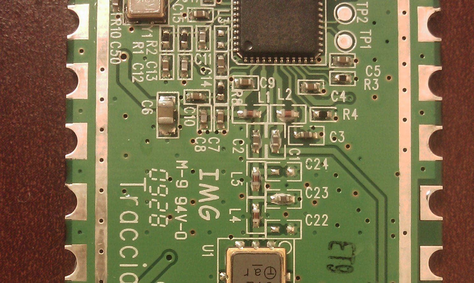
Click to zoom
Application Details
- Equipment Class
- TNB - Licensed Non-Broadcast Station Transmitter
- Date of Grant
- Jun 27, 2010
- Application Purpose
- Original Equipment
- Date of Application
- Jun 27, 2010
- Equipment Note
- RF460 MODULE
- Frequency Range
- 450.00000000 - 470.00000000
- Company
- Tracciare, Inc.
- Country
- United States
Documents & Files
Document Text
Text extracted from the exhibit documents filed with the FCC. Open a document above to read the original.
Users Manual
Revised: 2010.01.27 2 RF460 and Power Supply Installation Guide for S4e Meter January 27, 2010 Version 0.01A Revised: 2010.01.27 3 TABLE OF CONTENTS 1. Preparing the S4e Meter for Installation 4 2. The AMI Mounting Board 4 3. Assemble the AMI Mounting Board 5 4. Inserting the AMI Mounting Board 6 5. Attaching the Antenna 7 6. Closing the S4e Meter 7 LIST OF FIGURES Figure 1—Removal of Plastic Cover Figure 2—Lift Label Cover Figure 3—Removal of Electronic Housing Figure 4—AMI Mounting Board Fully Assembled Figure 5—Empty AMI Mounting Board Figure 6—Romove White Screws Figure 7—Power Supply Area Figure 8—Secure Power Supply Figure 9—RF460 Area Figure 10—Secure RF460 Figure 11—Separate the Electronic Housing and Meter Base Figure 12—Locate Power Leads Yellow/Gray Figure 13—Connect the Power Supply Leads Figure 14—Re-Connect the Yellow/Gray Leads Figure 15—Insert AMI Mounting Board Figure 16—Attach White Ribbon Cable Figure 17—Connect Antenna to the RF460 Board Figure 18—Position of the Antenna Figure 19—Securing the Antenna Figure 20—Place FCC Label Figure 21—Replace Plastic Cover Figure 22—Replace T-Seal DEVICE WARNING This device must be installed to provide a separation distance of at least 50 cm from all persons and must not be co-located or operating in conjunction with any other antenna or transmitter in its final in- stallation. Revised: 2010.01.27 4 Preparing the S4e Meter for Installation 1. Remove the Plastic Cover by rotating the cover counter-clockwise then pulling the cover away (see Figure 1). 2. Lift the label cover to expose the four mounting screws holding the Electronics Housing in place (see Figure 2). 3. Pull the Electronic Housing away from the Meter Base so that the AMI Mounting Board can be in- stalled (see Figure 3). Figure 1 Removal of Plastic Cover Figure 3 Removal of Electronics Housing Figure 2 Lift Label Cover The AMI Mounting Board The AMI Mounting Board should come pre-assembled when you receive it. If it is not, follow the in- structions on Page 5 for “Assemble the AMI Mounting Board”. If your AMI Mounting Board is assembled and looks like Figure 4 below, continue on Page 6 Figure 4 AMI Mounting Board Fully Assembled Revised: 2010.01.27 5 Assemble the AMI Mounting Board 1. Place the AMI Mounting with the White AMI Ribbon Cable pointing up (see Figure 5) 2. Remove the White Plastic Screws from the white Stand-Offs already positioned on the Mounting Board (see Figure 6) 3. Place the Power Supply in the area indentified by the small trace area (see Figure 7) 4. Secure the Power Supply with the white screws (see Figure 8) 5. Place the LGYR460 in the area indentified by the large trace area (see Figure 9) 6. Secure the LGYR460 with the white screws (see Figure 10) Figure 5 AMI Mounting Board Figure 6 Remove White Screws Figure 7 Power Supply Area Figure 8 Secure Power Supply Figure 9 LGYR460 Area Figure 10 Secure RF460 Revised: 2010.01.27 6 Inserting the AMI Mounting Board 1. Separate the Electronic Housing from the Meter Base (see Figure 11) 2. Locate and disconnect the Power Leads Connected to the Electronic Housing —Yellow and Gray (see Figure 12) 3. Connect the Power Supply to the terminals on the Electronic Housing (see Figure 13) 4. Re-Connect the Yellow and Gray Power Leads (see Figure 14) 5. Place the AMI Mounting Board into the Meter with the RF460 facing down (see Figure 15) 6. Attach the AMI Mounting Board’s White Ribbon cable to the Electronic Housing (see Figure 16) 7. Replace the Electronic Housing Screws and replace the Label Cover Figure 11 Separate the Electronic Housing and Meter Base Figure 12 Locate Power Leads Yellow/Gray Figure 13 Connect the Power Supply Leads Figure 14 Re-Connect Yellow/Gray Leads Figure 15 Insert AMI Mounting Figure 16 Attach White Ribbon Revised: 2010.01.27 7 Figure 20 Place the FCC Label Figure 22 Replace the T-Seal Figure 21 Replace the Plastic Cover Figure 19 Securing the Antenna Attaching the Antenna 1. Connect the antenna to the RF460 (see Figure 17) 2. Secure the antenna about 1.5” from the front edge of the Electronic Housing. It should be in con- tact with the Electronic Housing (see Figure 18) 3. Secure the antenna by using the tape supplied with your AMI Mounting Board Kit , Note the loca- tion of the Antenna before Taping. It should be 1.5” from the front edge of the Electronic Housing (see Figure 19) Closing the S4e Meter 1. Place the FCC Label supplied in your AMI Mounting Board Kit to the Label Cover (see Figure 20) 2. Replace the Plastic Cover and turn Clock-wise to tighten (see Figure 21) 3. Place the T-Seal and bend (see Figure 22) Figure 17 Connect the Antenna to the RF460 Board Figure 18 Position of the Antenna
Cover Letter(s)
Tracciare June 23.2010 Equipment Authorization Division Federal Communications Commission 7435 Oakland Mills Road Columbia, MD 21046 FCC lDr X4WRF460 Product Name: RF460 Reouest tor Confi dentialitv Pursuant to Sections 0.457 and 0.459 of the Commission's rules, we hereby request that the following documents be held confidential: . Schematics . Block diagram . Operation/TechnicalDescription . Tune-up Procedure . DC Voltages and Currents These materials contain trade secrets and proprietary information and are not customarily released to the public. The public disclosure of this information might be harmtul to the company and provide unjustified benefits to our competitors. Dat d rhis By: # Dayo, June 10 Jon A- Boe2 Prtnbd Chi3,l T*hnicel Offic.r On behalf o, : felaphone: fncciare lnc. 417-2/ttGS n 156 Alta Mesa Dr. Fort Worth Texas 76108
Cover Letter(s)
Tracc[are Febtuary 22, 2OlO Equipment Authorization Division Fedelal Communications commission 7435 oakland Mills Road Columbia, MD, 21046 FCC lD: X4WRF460 Reouest for Limited Modular Agoroval Tracciare respectfully submits this requestlor Limited Modulot Approvol for consideration regarding Fcc tD x4wRF450. Background lnformation. The Tracciare RF460 module is a 2 watt RF transceiver with frequency operation within the 450MHz to 470MHz ljcensed band. The module transmitter is desiSned for Part 90 emission mask D - 12.5 kHz channel bandwidth equipment. Based upon the installation location and number of channels required, channel license leases are purchased for operation. After license frequencies are identified, these are configured during the manufacturing process prior to field installation. Tracciare has designed a family of products utilizing the same RF450 radio module for the utility marketplace. Allexisting configurations have been submitted fortesting verification and approval. The numbered requirements forequipment authorization are listed and addressed below. 1. The modular transmitter must have its own RF shieldin8. This is intended to ensure that the module does not have to rely upon the shielding provided by the device into which it is installed in order for all modula r transmitter emissions to comply with Part 15 limits. lt is also intended to prevent coupling between the RF circuitry of the module and any wires or circuits in the device into which the module is installed. Such coupling may result in non-compliant operation. The RF460 modulartransmitter provides its'own RF shielding. 2. The modular transmitter must have buffered modulation/data inputs (if such inputs are provided) to ensure that the module will comply with Part 15 requirements under conditions of excessive data rates or over-mod u lation. The RF45O modular transmitter has buffer modulation/data inputs provided by the RF transceiver antegrated circuit that ensures consistent modulation at the designed data fate. 3. The modular transmitter must have its own power supply regulation. This is intended to ensure that the module willcomply with Part 15 requjrements regardless ofthe design ofthe power supplying circuitry in the device into which the module is instatled. 156 Alta Mesa Dr-Fort Worth Texas 75108 4. 5. 6. Tracciare The RF460 modular transmitter must be supplied a volta8e of 2.7 to 3.6 VDC with a current requirement of up to 3 amperes. ln our application, the RF460 modular transmitter mates to an application specmc board which supplies the power regulation aequired for the RF46O modular transmitter. Tracciare has submitted all current configurations and their respedive power supplies for FCC testing. The electric meter configuration utilizes the Texas lnstruments tM3S1601 microcontroller and the utility confiEu.ation utilizes the Teras lnstruments MSP430F2350 microcontroller. lt is the intent that the RF460 modular transmitter limited modular approval request be limited to the above two microcontrclleas. The modular transmitter must comply with the antenna requirements of s€cdon 15.203 and 15.204(c). The antenna must either be permanently attached or employ a "!nique" antenna coupler (at all connections between the module and the antenna, including the cable). Any antenna used with the module must be approved with the module, either at the time of initial authorization orthrough a Class llpermissive change. The "professionalinstallation" provision of s€ction 15.203 may not be applied to modules. The RF460 modular tra nsm itter is a Pan 90 licensed device. The anten na connection from the RF450 module is a custom 50 ohm impedance trace. The modular trdnsmitter must b€ tested in a stand-alone configuration, i.e., the module must not be inside another device during testing. Ihis is intended to demonstrate that the module is capable of complying with Part 15 emission limits regardless of the device into which it is eventually installed. Unless the transmitter module will be battery powered, it must comply with the AC line conducted requirements found in Section 15.207. AC or DC power lines and data inpuvoutput lines connected to the module must not contain ferrites, unless they will be marketed with the module {s€e Section 15.27(a)). the length of these lines shal, be length typicalof adual use or, ifthat length is unknown, at least 10 centimeters to insure that there is no coupling between the case of the module and supporting equipment. Any accessories, periph€rals, or suppoft equipment connected to the module during testing shall be unmodifiedorcommerciallyavailable (seeSection 15.31(i)). The RF45O modular tEnsmitter has been tested in a stand-alone configu€tion as well as all existing configurations per the above requirements. The modular transmitter must be labeled with its own FCC lD number, and, ifthe FCC ID is not visible when the module is installed inside another device, then the outside ofthe device into which the module is installed must also display a label referring to the enclosed module. This exteriot label can use wording such as the following: "Contains Transmitter Module FCC lD: XrZMODELI" or "Contains FCC lD: XrZMODELl." Any similarwording that exprcsses the same meaning may be used. The Grantee may eithea prcvide such a label, an example of which must be included in the application for equipment authorization, or, must provide adequate instructions along with the module which explain this requirement. ln the latter case, a copy ofthese instructions must be included in the application forequipment authorization. 156 Alta Mesa Dr.Fort Worth Texas 76108 Tracciare The RF460 modular transminer will be identmed internally eithe. by label on the module shield or etching on the shield cover itself per rcC requkements. The final configuration will display an exterior lab€l per FCC requirements. 't. The modular transmitter must comply with any specific rule or op€rating requirements applicable …
Text truncated - open the document above for the full version.
Cover Letter(s)
February 22,2010 Timco Engineering 849 N.W. State Road 45 PO Box 370 Newberry, FL 32669 Attn: Director of Certification Authoritv to Act as Aqent FCC On our behalf, I authorize Nemko USA, lnc., 802 N. Kealy, Lewisville, TX 75057, to act as our agent in the preparation of this application for equipment certification. I certify that submitted documents properly describe the device or system for which equipment certification is sought. I also certify that each unit manufactured, imported or marketed, as defined in Federal Communications Commission regulations will have affixed to it a label identicalto that submitted for approval with this application. We also authorize Nemko USA, lnc. to certify that neither the applicant nor any party to the application is subject to a denial of Federal benefits, that include FCC benefits, pursuant to Section 5301 of the Anti-Drug Abuse Act of 1988, 21 U.S.C. S 862 because of a conviction for possession or distribution of a controlled substance. For instances where our authorized agent signs the application for certification on our behalf, I acknowledge that all responsibility for complying with the terms and conditions for certification, as specified by Timco Engineering still resides with Tracciare lnc., 156 Alta Mesa Dr., Fort Worth, TX. 76108 Dated this zfdDay of February 20 10 Agency agreement expiration date: u2u2011 By: Jon A Boaz ture Printed Titte! Chief Technical Officer On behalf of : Telephone: Tracciare lnc. 156 Alta Mesa Dr. 817-2tl,4-5500 Fort Worth Texas 76108 www.tracciare. us
ID Label/Location Info
Size: 2.5” x 0.8125” Material: WHT ULTRPLT SEL Test Color: Black Label Color: White Roll Format: 1 across standard roll Barcode: Code39 Digits: 10 Digit Bar Code Starting: 5000001001 Increment: by One 2.5” .8125” Meter Label RF460 Tracciare, Inc. This device complies with Part 15 of the FCC rules. Operation is subject to the following two conditions: (1) this device may not cause harmful interference, and (2) this device must accept any interference received, including interference that may cause undesired operation. Contains X4W RF460 IC: 8809A-RF460 FCC: FOCUS AL FCC/IC Label and Position RF460 Tracciare, Inc. This device complies with Part 15 of the FCC rules. Operation is subject to the following two conditions: (1) this device may not cause harmful interference, and (2) this device must accept any interference received, including interference that may cause undesired operation. X4WRF460 IC: 8809A-RF460 Contains FCC: ICP FCC/IC Label and Position RF460 Tracciare, Inc. This device complies with Part 15 of the FCC rules. Operation is subject to the following two conditions: (1) this device may not cause harmful interference, and (2) this device must accept any interference received, including interference that may cause undesired operation. X4WRF460 IC: 8809A-RF460 Contains FCC: FOCUS AX-SD FCC/IC Label and Position RF460 Tracciare, Inc. This device complies with Part 15 of the FCC rules. Operation is subject to the following two conditions: (1) this device may not cause harmful interference, and (2) this device must accept any interference received, including interference that may cause undesired operation. X4WRF460 IC: 8809A-RF460 Contains FCC: S4e FCC/IC Label and Position RF460 Tracciare, Inc. This device complies with Part 15 of the FCC rules. Operation is subject to the following two conditions: (1) this device may not cause harmful interference, and (2) this device must accept any interference received, including interference that may cause undesired operation. X4WRF460 IC: 8809A-RF460 Contains FCC: Matrix Utility Module FCC/IC Label and Position RF460 Tracciare, Inc. This device complies with Part 15 of the FCC rules. Operation is subject to the following two conditions: (1) this device may not cause harmful interference, and (2) this device must accept any interference received, including interference that may cause undesired operation. X4WRF460 IC: 8809A-RF460 Contains FCC:
ID Label/Location Info
1 7/8” 7/8” Tracciare: RF460 FCC: X4WRF460 IC: 8809A-RF460 This device complies with Part 15 of the FCC rules. Operation is subject to the following two conditions: (1) this device may not cause harmful interference, and (2) this device must accept any interference received, including interference that may cause undesired operation. RF460 Label Location
RF Exposure Info
Prediction of MPE limit at a given distance Equation from page 18 of OET Bulletin 65, Edition 97-01 where:S = power density P = power input to the antenna G = power gain of the antenna in the direction of interest relative to an isotropic radiator R = distance to the center of radiation of the antenna Maximum peak output power at antenna input terminal:33.00(dBm) Maximum peak output power at antenna input terminal:1995.262315(mW) Antenna gain(maximum):6(dBi) Maximum antenna gain:3.981071706(numeric) Time Averaging:100(%) Prediction distance:50(cm) Prediction frequency:450(MHz) MPE limit for uncontrolled exposure at prediction frequency:0.300(mW/cm^2) Power density at prediction frequency:0.252843(mW/cm^2) Margin of compliance:-0.7(dB) This equates to:2.5284253W/m^2 2 4R PG S π =
Test Report
Nemko Test Report: 41771RUS1 Applicant: Tracciare, LLC 156 Alta Mesa Road Fort Worth, TX 76108 USA Equipment Under Test: RF460 (E.U.T.) FCC Identifier: X4WRF460 IC Identifier: 8809A-RF460 In Accordance With: FCC Part 90, Subpart I & Industry Canada RSS-119, Issue 9, Private Land Mobile Transmitter Tested By: Nemko USA Inc. 802 N. Kealy Lewisville, TX 75057-3136 TESTED BY: DATE: 09 February 2010 David Light, Senior Wireless Engineer APPROVED BY: DATE: 15 February 2010 Tom Tidwell, Telecom Direct Total Number of Pages: 33 Nemko USA, Inc. FCC PART 90, SUBPART I & RSS-119 PRIVATE LAND MOBILE TRANSMITTERS EQUIPMENT: RF460 PROJECT NO.: 41771RUS1 Page 2 of 33 Table of Contents SECTION 1. SUMMARY OF TEST RESULTS 3 SECTION 2. GENERAL EQUIPMENT SPECIFICATION 5 SECTION 3. RF POWER OUTPUT 7 SECTION 4. MODULATION CHARACTERISTICS 8 SECTION 5. OCCUPIED BANDWIDTH 9 SECTION 6. SPURIOUS EMISSIONS AT ANTENNA TERMINALS 11 SECTION 7. FIELD STRENGTH OF SPURIOUS EMISSIONS 14 SECTION 8. FREQUENCY STABILITY 15 SECTION 9. TRANSIENT FREQUENCY BEHAVIOR 17 SECTION 10. RECEIVER SPURIOUS EMISSIONS AT ANTENNA TERMINALS 20 SECTION 11. TEST EQUIPMENT LIST 23 ANNEX A - TEST METHODOLOGIES 24 ANNEX B - TEST DIAGRAMS 29 Nemko USA, Inc. FCC PART 90, SUBPART I & RSS-119 PRIVATE LAND MOBILE TRANSMITTERS EQUIPMENT: RF460 PROJECT NO.: 41771RUS1 Page 3 of 33 Section 1. Summary of Test Results Manufacturer: Tracciare, LLC Model No.: RF460 Serial No.: None General: All measurements are traceable to national standards. These tests were conducted on a sample of the equipment for the purpose of demonstrating compliance with FCC Part 90, Subpart I and Industry Canada RSS-119. New Submission Production Unit Class II Permissive Change Pre-Production Unit THIS TEST REPORT RELATES ONLY TO THE ITEM(S) TESTED. THE FOLLOWING DEVIATIONS FROM, ADDITIONS TO, OR EXCLUSIONS FROM THE TEST SPECIFICATIONS HAVE BEEN MADE. See “ Summary of Test Data”. Nemko USA, Inc. authorizes the above named company to reproduce this report provided it is reproduced in its entirety and for use by the company’s employees only. Any use which a third party makes of this report, or any reliance on or decisions to be made based on it, are the responsibility of such third parties. Nemko USA, Inc. accepts no responsibility for damages, if any, suffered by any third party as a result of decisions made or actions based on this report. This report applies only to the items tested. Nemko USA, Inc. FCC PART 90, SUBPART I & RSS-119 PRIVATE LAND MOBILE TRANSMITTERS EQUIPMENT: RF460 PROJECT NO.: 41771RUS1 Page 4 of 33 Summary of Test Data NAME OF TEST PARA. NO. RESULT RF Power Output 90.205 Complies Audio Frequency Response TIA EIA-603.3.2.6 1 NA Audio Low-Pass Filter Response TIA EIA-603.3.2.6 1 NA Modulation Limiting TIA EIA-603.3.2.6 Complies Occupied Bandwidth 90.210 Complies Spurious Emissions at Antenna Terminals 90.210 Complies Field Strength of Spurious Emissions 90.210 Complies Frequency Stability 90.213 Complies Transient Frequency Behavior 90.214 Complies Receiver Spurious Emissions RSS GEN Complies Footnotes: 1 The DUT has no audio components. Nemko USA, Inc. FCC PART 90, SUBPART I & RSS-119 PRIVATE LAND MOBILE TRANSMITTERS EQUIPMENT: RF460 PROJECT NO.: 41771RUS1 Page 5 of 33 Section 2. General Equipment Specification Supply Voltage Input: 120 Vac Frequency Range: 450 to 470 MHz Necessary Bandwidth: 11.8 kHz (2 x 3.5kHz) + (2 x (4800bps/2)) = 11.8 kHz Type(s) of Modulation: F3E (Voice) F1D F2D D7W (QAM) Other Emission Designator: 11K8F1D (2 x 3.5kHz) + (2 x (4800bps/2)) = 11.8 kHz Output Impedance: 50 ohms RF Power Output (rated): 2.0 Watts Channel Spacing(s): 12.5 kHz Operator Selection of Operating Frequency: Factory set Power Output Adjustment Capability: None Nemko USA, Inc. FCC PART 90, SUBPART I & RSS-119 PRIVATE LAND MOBILE TRANSMITTERS EQUIPMENT: RF460 PROJECT NO.: 41771RUS1 Page 6 of 33 System Description The RF460 is a wireless transmitter for relaying power usage from electric power meters. System Diagram Nemko USA, Inc. FCC PART 90, SUBPART I & RSS-119 PRIVATE LAND MOBILE TRANSMITTERS EQUIPMENT: RF460 PROJECT NO.: 41771RUS1 Page 7 of 33 Section 3. RF Power Output NAME OF TEST: RF Power Output PARA. NO.: 2.985 TESTED BY: David Light DATE: 04 February 2010 Measurement Results: Complies. Measurement Data: Frequency (MHz) Measured Power (dBm) Measured Power (Watts) Rated Power (Watts) 450.0125 33.00 2 2 460.0000 33.01 2 2 469.9875 33.01 2 2 Spectrum Analyzer Settings: RBW: 1 MHz VBW: 1 MHz Detector: Max Peak Measurement Conditions: Temperature: 22 °C Humidity: 31 % Test Equipment Used: 1036-1082-1469-1472 Measurement Uncertainty: +/- 1.7 dB Nemko USA, Inc. FCC PART 90, SUBPART I & RSS-119 PRIVATE LAND MOBILE TRANSMITTERS EQUIPMENT: RF460 PROJECT NO.: 41771RUS1 Page 8 of 33 Section 4. Modulation Characteristics NAME OF TEST: Modulation Characteristics PARA. NO.: 2.987 TESTED BY: David Light DATE: 04 February 2010 Measurement Results: Complies. Measurement Data: Maximum deviation for non-voice modulation 3.5 kHz. Limit: 12 kHz Measurement Conditions: Temperature:22 °C Humidity:45% Measurement Uncertainty: +/- 1.7 dB Description of modulation: FM Test Equipment Used: 1036-1082-1469-1472 Measurement Uncertainty: +/- 1.7 dB Nemko USA, Inc. FCC PART 90, SUBPART I & RSS-119 PRIVATE LAND MOBILE TRANSMITTERS EQUIPMENT: RF460 PROJECT NO.: 41771RUS1 Page 9 of 33 Section 5. Occupied Bandwidth NAME OF TEST: Occupied Bandwidth PARA. NO.: 2.989 TESTED BY: David Light DATE: 04 February 2010 Measurement Results: Complies. Measurement Data: Attached Measurement Conditions: Temperature:22 °C Humidity:31% Measurement Uncertainty: +/- 1X10 -7 ppm Note: The data presented is representative of the worst-case of low, mid, and high frequency channels (450.0125 MHz, 460.0000 MHz, and 469.0875 MHz). Nemko USA, Inc. FCC PART 90, SUBPART I & RSS-119 PRIVATE LAND MOBILE TRANSMITTERS EQUIPMENT: RF460 PROJECT NO.: 41771RUS1 Page 10 of 33 Test Data – Occupied Bandwidth Nemko USA, Inc. FCC PART 9…
Text truncated - open the document above for the full version.
Test Setup Photos
CFR 47, PART 15, SUBPART B CLASS B VERIFICATION REPORT NO.: 41771EUS1 EQUIPMENT: RF460 Page 11 of 21 Test Photographs - Test # CEPV-01 CFR 47, PART 15, SUBPART B CLASS B VERIFICATION REPORT NO.: 41771EUS1 EQUIPMENT: RF460 Page 16 of 21 Test Photos
Contact Information
Applicant
Jon A Boaz(CTO)
Test Firm
Nemko USA, Inc.Scott Oates
Technical Specifications
| # | Rule Parts | Frequency Range | Power Output | Emission | Tolerance |
|---|---|---|---|---|---|
| 1 | 90 | 450 MHz - 470 MHz | 2 W | 11K8F1D | Amp |