X7CAP8120802.11abgn Acess Point
Avaya LLC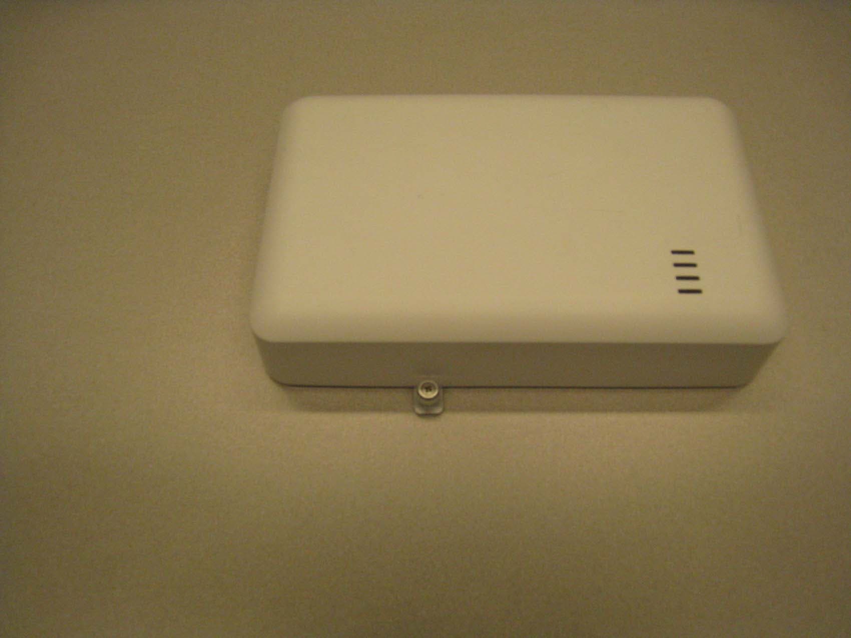
Click to zoom
Application Details
- Equipment Class
- NII - Unlicensed National Information Infrastructure TX
- Date of Grant
- Mar 11, 2010
- Application Purpose
- Original Equipment
- Date of Application
- Mar 10, 2010
- Equipment Note
- 802.11abgn Acess Point
- Frequency Range
- 5190.00000000 - 5230.00000000
- Company
- Avaya LLC
- Country
- United States
Documents & Files
Document Text
Text extracted from the exhibit documents filed with the FCC. Open a document above to read the original.
Users Manual
Nortel WLAN 8100 Regulatory Information - AP 8120 Release: 1.0 Document Revision: 01.AD www.nortel.com NN47251-104 . Nortel WLAN 8100 Release: 1.0 Publication: NN47251-104 Document status: Draft Document release date: 10 February 2010 Copyright © 2010 Nortel Networks. All Rights Reserved. While the information in this document is believed to be accurate and reliable, except as otherwise expressly agreed to in writing NORTEL PROVIDES THIS DOCUMENT "AS IS" WITHOUT WARRANTY OR CONDITION OF ANY KIND, EITHER EXPRESS OR IMPLIED. The information and/or products described in this document are subject to change without notice. Nortel, Nortel Networks, the Nortel logo, and the Globemark are trademarks of Nortel Networks. All other trademarks are the property of their respective owners. . 3 . Contents Regulatory Compliance Statements5 Federal Communications Commission (FCC) Compliance Notices 5 Class B Interference Statement 5 FCC Caution: 6 RF Radiation Exposure and Hazard Statement 6 Non-Modification Statement 6 Deployment Statement 6 Dynamic Frequency Selection (DFS) in the 5.0 GHz UNII bands 6 Canadian IC Statements 7 European Union and European Free Trade Association (EFTA) Regulatory Compliance 7 Declaration of Conformity 8 European Community Declaration of Conformity 9 Countries of Operation and Restrictions of Use in the European Community 11 Operation Using the 2.400 to 2.4835 GHz Channels in the European Community 11 Operation Using the 5.15 to 5.25 GHz, 5.25 to 5.35 GHz, and 5.470 to 5.725 GHz Channels in the European Community 11 Dynamic Frequency Selection (DFS) 12 Transmit Power Control 12 Antenna Statement 13 English15 Cable requirements 15 Mounting a wireless LAN access point on a wall 15 Installing an Access Point with a ceiling grid adaptor 16 Safety Messages 17 Nortel WLAN 8100 Regulatory Information - AP 8120 NN47251-104 01.AD Draft 10 February 2010 Copyright © 2010 Nortel Networks. All Rights Reserved. . 4 Nortel WLAN 8100 Regulatory Information - AP 8120 NN47251-104 01.AD Draft 10 February 2010 Copyright © 2010 Nortel Networks. All Rights Reserved. . 5 . Regulatory Compliance Statements The Avaya WLAN 8100 product line consists of the following models: •AP 8120-A1 • AP 8120-E1 This section contains regulatory compliance statements for these units. Federal Communications Commission (FCC) Compliance Notices This section includes the following FCC statements for the AP 8120-A1 access point: •FCC ID: •Class B Interference Statement •RF Radiation Exposure and Hazard Warning •Non-Modification Statement •Deployment Statement Class B Interference Statement This equipment has been tested and found to comply with the limits for a Class B digital device, pursuant to Part 15 of the FCC Rules. These limits are designed to provide reasonable protection against harmful interference in a residential installation. This equipment generates, uses, and can radiate radio frequency energy and, if not installed and used in accordance with the instructions, may cause harmful interference to radio communications. However, there is no guarantee that interference will not occur in a particular installation. If this equipment does cause harmful interference to radio or television reception, which can be determined by turning the equipment off and on, the user is encouraged to try to correct the interference by one or more of the following measures: •Reorient or relocate the receiving antenna. •Increase the separation between the equipment and receiver. Nortel WLAN 8100 Regulatory Information - AP 8120 NN47251-104 01.AD Draft 10 February 2010 Copyright © 2010 Nortel Networks. All Rights Reserved. . 6Regulatory Compliance Statements •Connect the equipment into an outlet on a circuit different from that to which the receiver is connected. •Consult the dealer or an experienced radio/TV technician for help. FCC Caution: This device complies with Part 15 of the FCC Rules. Operation is subject to the following two conditions: (1) This device may not cause harmful interference, and (2) this device must accept any interference received, including interference that may cause undesired operation. RF Radiation Exposure and Hazard Statement To ensure compliance with FCC RF exposure requirements, this device must be installed in a location such that the antenna of the device will be greater than 20 cm (8 in.) away from all persons. Using higher gain antennas and types of antennas not covered under the FCC certification of this product is not allowed. Installers of the radio and end users of the product must adhere to the installation instructions provided in this manual. This transmitter must not be co-located or operating in conjunction with any other antenna or transmitter. Non-Modification Statement Use only the supplied internal antenna. Unauthorized antennas, modifications, or attachments could damage the AP 8120-A1 and violate FCC regulations. Any changes or modifications not expressly approved by the party responsible for compliance could void the user’s authority to operate this equipment. This device must be operated with the CAT-5 Ethernet cable installed on each activated Ethernet Port of an AP 8120-A1 access point to ensure compliance with the Class B emissions standards. Failure to comply with this installation requirement may cause the device to operate in excess of the allowable emissions limits Deployment Statement This product is certified for indoor deployment only.Do notinstall or use this product outdoors. Dynamic Frequency Selection (DFS) in the 5.0 GHz UNII bands The AP 8120-A1 access point has been prohibited, via software, from operating in the 5250 to 5350 MHz and 5470 to 5725 MHz frequency bands for the US and Canada because it cannot meet the DFS requirements as outlined in the rules of the FCC for Part 15, Subpart E that come into force on July 20, 2007. Nortel WLAN 8100 Regulatory Information - AP 8120 NN47251-104 01.AD Draft 10 February 2010 Copyright © 2010 Nortel Networks. All Rights Re…
Text truncated - open the document above for the full version.
Cover Letter(s)
Elliott TCB 684 W. Maude Ave Sunnyvale, CA, 94085 RE: FCC/IC application for Broadcom Corporation, FCC ID: X7CAP8120, IC ID: 3794G- AP8120 To whom it may concern: The enclosed documents constitute a formal submittal and application for Equipment Authorization for an 802.11abgn access point to the following rules: Subpart C of Part 15 of FCC Rules (CFR 47), Section 15.247 Subpart E of Part 15 of FCC Rules (CRF 47) RSS-Gen Issue 2, June 2007, “General Requirements and Information for the Certification of Radiocommunication Equipment” RSS-210, Issue 7, June 2007, “Low-power Licence-exempt Radiocommunication Devices (All Frequency Bands): Category I Equipment” The device operates in the 2.4GHz, 5.15-5.25GHz and 5.725-5.850 GHz bands. The device incorporates two radios. One is configured for operation in the 2.4GHz band, while the other operates in the 5GHz bands. Elliott Laboratories, as duly authorized agent prepared this submittal. A copy of the letter of our appointment as agent is included with the application. If there are any questions or if further information is needed, please contact Elliott Laboratories for assistance. Sincerely, Mark Hill Staff Engineer MEH/dmg
Cover Letter(s)
Elliott TCB 684 West Maude Ave. Sunnyvale, CA. 94085 February 24,2014 Gentlemen: This is yotu letter of autlrorization to accept our appointuent of Elliott Laboratories, Inc. as our Agent for Avaya" [nc, to sigr applications before Elliott TCB and to make representations to you on our behalf. Elliott Laboratories, Inc. is to receive and exchange data between our company and Elliott TCB. I hereby certiff on behalf of Avayq Inc, 4655 Great America Parlnuay, Santa Clara, California95014 that neither Applicant nor any party to the application (officers, directors, aod 5% shareholders) is subject to a denial of Federal benefits that includes FCC benefits pursuant to section 5301 of the Anti-Drug Abuse Act of 1988, 21 U.S.C. 853a. Sincerely, Vipin Naik Managero Regulatory Compliance
Cover Letter(s)
February 24,2010 Elliott TCB 684 West Maude Ave. Surmyvaleo CA.94085 FCC ID: X7CAP8120 Dear Examiner: I am onritins to avoid the possibility of an inadvertent disclosure of proprietary information. The accompanying Form 731 is being filed with the commission on our behalf by Elliott Laboratories, Inc.o a consulting and testing laboratory. Included as exhibits with the enclosed application are block diagramso schematics, and a detailed description of the theory of operation ofthe device. It is our intention to provide Elliott TCB and the commission with a frrll disclosure of our product so that its merits can be evaluated. Indeedo wo are pleased to provide any further information that the commission might wish to see. It is not otrr intentiono howevero to make our proprietary process a mattpr of public fecord. In view of the fact that the block diagrams, schematicso and associated theory of operation disclose the mechanism of our process, we ask that these portions (block diagrams, schematics, and theory of operation) of our application be withheld from public inspection as provided under FCC section 0.459. These documents contain details of the proprietry operation of product. These details are not readily discernible - even to technically sophisticated individuals - from our hardware and constitute trade secrets. We request therefore that these documents be segregated from the body of our evaluation report and withheld from public inspection. Thank you for your afiention. Please let the undersigned know if Elliott TCB or the Commission disagrees with orn position or requires furttrer justification. Sincerely, -+ -r--- _a-ut - - f \-rta\ /, t,ttlY t-/ -/ tr-v 7 VipinNaik Manager, RegulatoryCompliance
Cover Letter(s)
Page 1 of 2 March 9, 2010 RE: FCC ID: X7CAP8120, IC: 3794G-AP8120 Attention: Please find our responses to your comments on this application below: 1. Terms and conditions form S56501 was not submitted. Please submit. Response: See uploaded Terms and Conditions Form. 2. User manual and operational description were from the Nortel Communication. Please explain how Nortel Communication is related to Avaya, Inc Response: The Nortel group that was responsible for the AP8120 was acquired by Avaya just prior to the application. Some of the documentation is still in the process of being converted over from Nortel to Avaya. 3. User manual attached is draft version. Final version of user manual should be submitted when available to the TCB for upload to the FCC website. The FCC expects the formal version of the manual to be uploaded before the product is released. Response: Noted. Avaya is aware of the need to upload a final version of the User’s Manual. 4. Schematics and block diagram are from Accton Inc, not from the applicant. Please explain how BCM4342mp-802.11a/b/g/n mini-PCI radio card relates to AP8120. Response: Accton is the contracted designer for the product. Nortel/Avaya contracted them to develop the product on their behalf. The BCM4342mp-802.11a/b/g/n mini-PCI radio card is a subassembly within the AP8120 that contains the RF portion of the product. The AP8120 has two of these subassemblies installed. 5. Hardware Specification document is submitted in place of a Block diagram. The various block diagrams spread through this document do not show the rf frequencies. Please provide a document with just the block diagram or explain how the submitted document meets the requirements. Response: See new block diagram exhibit. This supersedes the previously uploaded file. Page 2 of 2 6. AC line conducted emissions data was not found in the test data for the DTS report although results are included in the summary tables. Please submit. Response: See revised DTS test report. 7. Please review the band edge conducted graph for the 802.11g mode (p139 of 185 in the test report / page 11 of 57 in T78130 DTS conducted) – the solid red line does not appear to be at -20dBc. Response: See revised DTS test report. 8. AC line conducted emissions data was not found in the test data for the NII report although results are included in the summary tables. Please submit. Response: See revised NII test report. 9. The user’s manual indicates that the device can operate outside of the frequency bands covered by your application (specifically for Europe). Please provide an attestation letter from Avaya that explicitly states that the systems sold into the US and Canada are limited to operation across channels 1 through 11 in the 2.4GHz band and channels 36 through 48 in the 5150-5250 MHz band with no access for the user to modify the operating range outside of these settings. Response: Uploaded “AP8120_US_Canada_Attestation_Letter” Regards, Mark Hill Staff Engineer Updated Exhibits: R78416, DTS Test Report R78418, UNII Test Report Terms and Conditions Block Diagram AP8120_US_Canada_Attestation_Letter
RF Exposure Info
EMC Test Data Client: Contact: Standard: Test Specific Details General Test Configuration Yes 0.719 AvayaJob Number: J7865 Model: AP 8120 T-Log Number: T78130 Account Manager: Dean Eriksen Vipin Naik FCC 15.247Class: N/ A Maximum Permissible Exposure Objective: The objective of this test session is to perform final qualification testing of the EUT with respect to the specification listed above. Date of Test: 2/23/2010 Test Engineer: Mark Hill Calculation uses the free space transmission formula: S = (PG)/(4 πd 2 ) Where: S is power density (W/m 2 ), P is output power (W), G is antenna gain relative to isotropic, d is separation distance from the transmitting antenna (m). Summary of Results Device complies with Power Density requirements at 20cm separation: Power Density (mW/cm^2) Modifications Made During Testing No modifications were made to the EUT during testing Deviations From The Standard No deviations were made from the requirements of the standard. T78130 (DTS Conducted)MPE CalcPage 1 of 2 EMC Test Data Client: Contact: Standard: AvayaJob Number: J7865 Model: AP 8120 T-Log Number: T78130 Account Manager: Dean Eriksen Vipin Naik FCC 15.247Class: N/ A Use: General Use Antenna: Maximum eirp is calculated as follows: Used for Multi ple Transmitters One 2.4GHz and one 5.7GHz o peration PeakAveragedBmWWdBm 2400 - 2483.5 OFDM25.6-8.434.02.518 2401 - 2483.5 CCK-18.85.424.20.264 5150 - 5250 OFDM-13.58.922.40.17440-- 5725 - 5850 OFDM22.3-8.130.41.094511.09430.39 23.61235.58 One 2.4GHz and one 5.15-5.25GHZ o peration PeakAveragedBmWWdBm 2400 - 2483.5 OFDM25.6-8.434.02.518 2401 - 2483.5 CCK-18.85.424.20.264 5150 - 5250 OFDM-13.58.922.40.174410.17422.41 5725 - 5850 OFDM22.3-8.530.81.20850-- 22.69234.30 Worse Case Condition EIRP mW 3612.00 Total EIRP Total EIRP Channels Used EIRP 2.51834.01 1112.51834.01 Power Density (S)MPE Limit at 20 cmat 20 cm mW/cm^2mW/cm^2 0.7191.000 EIRP Channels Available Channels Used 111 BandMode Output Power Antenna gain (Max) Totals: 2.4GHz - 5.41dBi/5.15-5.25GHz - 5.91dBi/5.7-5.8GHz - 5.09dBi Effective Gain for Mimo: 8.41dBi/8.91dBi/8.09 dBi The system allows for one radio to operate in the 2.4GHz band and one radio to operate in the 5GHz bands simultaneously. It prevents both radios operating in the same band at the same time. Uses the average power for each channel (where given), otherwise uses the peak power Totals: BandMode Output Power Antenna gain (Max) Channels Available T78130 (DTS Conducted)MPE CalcPage 2 of 2
Test Report
File: R78418 Page 1 of 23 EMC Test Report Application for Grant of Equipment Authorization pursuant to Industry Canada RSS-Gen Issue 2 / RSS 210 Issue 7 FCC Part 15, Subpart E Model: WLAN AP 8120 IC CERTIFICATION #: 3794G-AP8120 FCC ID: X7CAP8120 APPLICANT: Avaya 4655 Great America Parkway Santa Clara, CA 95054 TEST SITE(S): Elliott Laboratories 684 W. Maude Avenue Sunnyvale, CA 94085 and 41039 Boyce Road. Fremont, CA. 94538-2435 IC SITE REGISTRATION #: 2845A-1; 2845A-2; 2845B-3; 2845B-4, 2845B- 5 REPORT DATE: March 5, 2010 FINAL TEST DATES: January 28, 29, 31, February 3, 4, 9 and 11, 2010 AUTHORIZED SIGNATORY: ______________________________ Mark E. Hill Staff Engineer Elliott Laboratories Elliott Laboratories is accredited by the A2LA, certificate number 2016-01, to perform the test(s) listed in this report, except where noted otherwise. This report shall not be reproduced, except in its entirety, without the written approval of Elliott Laboratories Testing Cert #2016-01 Elliott Laboratories -- EMC Department Test Report Report Date: March 5, 2010 File: R78418 Page 2 of 23 REVISION HISTORY Rev# Date Comments Modified By - March 5, 2010 First release Elliott Laboratories -- EMC Department Test Report Report Date: March 5, 2010 File: R78418 Page 3 of 23 TABLE OF CONTENTS COVER PAGE........................................................................................................................................................... 1 REVISION HISTORY ................................................................................................................................................2 TABLE OF CONTENTS ............................................................................................................................................3 SCOPE..........................................................................................................................................................................4 OBJECTIVE ................................................................................................................................................................5 STATEMENT OF COMPLIANCE...........................................................................................................................5 DEVIATIONS FROM THE STANDARDS ..............................................................................................................5 TEST RESULTS SUMMARY ...................................................................................................................................6 UNII / LELAN DEVICES ........................................................................................................................................6 GENERAL REQUIREMENTS APPLICABLE TO ALL BANDS..........................................................................7 MEASUREMENT UNCERTAINTIES....................................................................................................................7 EQUIPMENT UNDER TEST (EUT) DETAILS ......................................................................................................8 GENERAL................................................................................................................................................................8 OTHER EUT DETAILS...........................................................................................................................................8 ANTENNA SYSTEM ..............................................................................................................................................8 ENCLOSURE...........................................................................................................................................................8 MODIFICATIONS...................................................................................................................................................8 SUPPORT EQUIPMENT.........................................................................................................................................8 EUT INTERFACE PORTS ......................................................................................................................................9 EUT OPERATION ...................................................................................................................................................9 TEST SITE.................................................................................................................................................................10 GENERAL INFORMATION .................................................................................................................................10 CONDUCTED EMISSIONS CONSIDERATIONS ..............................................................................................10 RADIATED EMISSIONS CONSIDERATIONS ..................................................................................................10 MEASUREMENT INSTRUMENTATION ............................................................................................................11 RECEIVER SYSTEM ............................................................................................................................................11 INSTRUMENT CONTROL COMPUTER ............................................................................................................11 LINE IMPEDANCE STABILIZATION NETWORK (LISN)...............................................................................11 FILTERS/ATTENUATORS ..................................................................................................................................12 ANTENNAS...........................................................................................................................................................12 ANTENNA MAST AND EQUIPMENT TURNTABLE ................................................................…
Text truncated - open the document above for the full version.
Contact Information
Applicant
Gwendolyn Faino(Legal Director)
Test Firm
NTS Labs, LLC Fremont & NewarkDavid Bare
Technical Specifications
| # | Rule Parts | Frequency Range | Power Output |
|---|---|---|---|
| 3 | 15E | 5.19 GHz - 5.23 GHz | 22.00 mW |