X9E-DMCXACTGPS TRACKER
JABIL CIRCUIT (WUXI) CO., LTD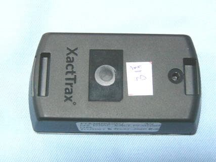
Click to zoom
Application Details
- Equipment Class
- PCB - PCS Licensed Transmitter
- Date of Grant
- Apr 19, 2010
- Application Purpose
- Original Equipment
- Date of Application
- Apr 19, 2010
- Equipment Note
- GPS TRACKER
- Frequency Range
- 1850.20000000 - 1909.80000000
- Country
- China
Documents & Files
Document Text
Text extracted from the exhibit documents filed with the FCC. Open a document above to read the original.
Users Manual
Quick Start Guide for Xact Trax Plus Model Number: XT50 Controls 1. Panic Button - Sends an alert notification. 2. Power button - turns the Xact Trax on or off and can set device level features 3. Mini USB Connector - Battery charging and PC connection. 4. Power LED - Red (only applicable if not disabled) 5. GSM LED - Green (only applicable if not disabled) 6. GPS LED - Amber (only applicable if not disabled) Activating Your Xact Trax Plus 1. Connect your device to your PC for a complete charge. Power on the device by pressing the power button for 1.5 seconds (until the Power LED flashes Green), Place your device near a window at this time if possible. 2. While connected to your PC; go to http:\\www.xacttrax.com and click on register new device. Follow the on screen instructions. 3. By activating the Xact Trax Plus device you are agreeing to all terms and conditions. Please Read all Terms and conditions carefully before activating your device. 1 2 3 4 5 6 Using your Xact Trax Plus for the first time (Power On) 1. To turn on your Xact Trax Plus device press the power button for 1.5 seconds until the Power LED begins to flash Green. This LED will flash Red once fully powered on. 2. Place your Xact Trax Plus device outside or close to a window the first time until you see the GSM Signal (Green) and GPS Satellite (Amber) LED’s flash, to lock the initial location. Once your Trax device is able to track your location it is ready for use. (this could take several minutes to acquire GSM and GPS signal based on geo- graphical location and environmental conditions.) 3. Once the Xact Trax Plus device has a GSM and GPS Satellite fix, place your Xact Trax Plus device on the object you wish to track. 4. Login to http:\\portal.xacttrax.com to follow and manage your device. Power down 1. Press the power button for > 5 seconds. 2. All LED’s flash Red to indicate the device is powering down. 3. All LED’s shut off when powered off. Sending an Panic request Press and hold the Panic button for longer then 3 seconds. (Please make sure this feature is enabled on your device; to do so log in to xacttrax.com). Please see website for further details on use of this feature. Park Mode A temporary Geofence with a radius of 300 meters will be active around the current device location while in Park Mode. This Geofence will be deleted once the device is returned to Normal Operation. 1. While in Normal Operation mode, Hold the Power button for > 3 seconds. 2. All LED’s will flash Red at 3 second intervals to indicate park Mode is active. To return to Normal Operation 1. Hold the Power button again for > 3 seconds. 2. The LED’s will return to the Normal Operation state. Walk Mode Geofence alerts will be temporarily disabled while in Walk Mode. The alerts will be re-enabled when the Xact Trax Plus returns to Normal Operation. 1. From Normal Operation mode, hold the Power button for 1.5 seconds. 2. All LED’s will flash Green at 3 second intervals to indicate walk Mode is active. To return to Normal Operation 1. Hold the Power again button for 1.5 seconds. 2. The LED’s will return to the Normal Operation state. LED States If LED is off no GSM or GPS signal can be found. LED StatesBlinkingAll GreenAll AmberAll Red POWER Red - Power is on Walk Mode Park Mode Powering Off GSM Green - Connected to celluler Network GPS Amber - Obtained GPS Satellite Fix Warranty Information One-Year Limited Warranty This limited warranty sets forth all Xact Technology responsibilities regarding your product. There are no other expressed or implied warranties from Xact Technology. Warranty Service Provided If you purchased the product new from an approved vendor, Xact Technology warrants the equipment against defects in material and workmanship for a period of one (1) year from the original date of purchase. This warranty is in lieu of all other express warranties. This warranty period begins when you purchase the product and continues for one (1) year unless you sell or rent the unit, in which case the warranty period ends. Xact Technology disclaims any implied warranty, including the warranty of merchantability and the warranty of fitness for a particular purpose, as of the date of one year from your original purchase of the product Xact Technology assumes no responsibility for any special, incidental, or consequential damages. This warranty gives you specific legal rights and you may have other rights which vary from state to state. Some states do not allow the exclusion or limitations of special, incidental, or consequential damages or limitations on how long a warranty lasts, so the above exclusion or limitation may not apply to you. Xact Technology, LLC New York, NY Customer Service www.xacttechnology.com Printed on Recycled Paper ©2009 Xact Technology, LLC All rights reserved. Warranty Service Not Provided This warranty does not cover damage resulting from accident, misuse, abuse, improper installation or operation, lack of reasonable care, unauthorized modification, or the affixing of any attachment not provided or approved by Xact Technology with the equipment, and/or loss of parts. This warranty is voided in the event any unauthorized person opens, alters, or repairs the product. All Xact Technology equipment being returned for repair must be suitably packaged with all original components. Please use only the USB cable that has been supplied with your device for PC connection and charging your Xact Trax Plus. Any changes or modifications to the unit not expressly approved by Xact will void your warranty and invalidate your authority to operate this equipment. Warning: The FCC and FAA have not certified the Xact Trax Plus for use in any aircraft (neither portable nor permanent installation). Therefore, Xact cannot support this type of application or installation.
Users Manual
Federal Communications Commission (FCC) Statement 15.21 You are cautioned that changes or modifications not expressly approved by the part responsible for compliance could void the user’s authority to operate the equipment. 15.105(b) Federal Communications Commission (FCC) Statement This equipment has been tested and found to comply with the limits for a Class B digital device, pursuant to part 15 of the FCC rules. These limits are designed to provide reasonable protection against harmful interference in a residential installation. This equipment generates, uses and can radiate radio frequency energy and, if not installed and used in accordance with the instructions, may cause harmful interference to radio communications. However, there is no guarantee that interference will not occur in a particular installation. If this equipment does cause harmful interference to radio or television reception, which can be determined by turning the equipment off and on, the user is encouraged to try to correct the interference by one or more of the following measures: -Reorient or relocate the receiving antenna. -Increase the separation between the equipment and receiver. -Connect the equipment into an outlet on a circuit different from that to which the receiver is connected. -Consult the dealer or an experienced radio/TV technician for help. This device complies with part 15 of the FCC Rules. Operation is subject to the condition that this device does not cause harmful interference. FCC RF Radiation Exposure Statement: 1. This Transmitter must not be co-located or operating in conjunction with any other antenna or transmitter. 2. This equipment complies with FCC RF radiation exposure limits set forth for an uncontrolled environment. This equipment should be installed and operated with a minimum distance of 20 centimeters between the radiator and your body.
Block Diagram
MCU Board (WMP100) Memory GPS R/C Model Control SIM Card Crystal Frequency: 32.768KHZ 32KHZ USB PORT GPS ANTENNA GSM ANTENNA Diagram
Cover Letter(s)
Jabil Circuit (Wuxi) Co., Ltd. Lot J9, J10 Export Precessing Zone, Wuxi City, Jiangsu Province PRC Federal Communications Commission 7435 Oakland Mills Road Columbia, MD Date: April 14, 2010 SUBJECT: FCC Application for FCC ID: X9E-DMCXACT To Whom It May Concern: We, the undersigned, hereby declare that the device will not be worn on the body. If you have any question or concerns, please contact us Regards, Jeanne Jiang / Manager Jabil Circuit (Wuxi) Co., Ltd.
Cover Letter(s)
Jabil Circuit (Wuxi) Co., Ltd. Lot J9, J10 Export Precessing Zone, Wuxi City, Jiangsu Province PRC Experimental Licensing Branch, OET Federal Communications Commission 445 12 th Street, S.W. Washington, D.C. 20554 Date: April 14, 2010 ATTN: Attestation Cover Letter Dear Regulatory Authority, We, the undersigned, hereby declare that the original module Test Report / FCC ID: O9EWMP100 is being submitted with this application. The Test Data from the modular approval continues to be representative for the current product under test in this FCC application for Certification. The module is electrically identical to the original approval for this Certification. Regards, Jeanne Jiang / Manager Jabil Circuit (Wuxi) Co., Ltd.
External Photos
EUT top view EUT bottom view
ID Label/Location Info
The Label must not be a stick-on paper label. The Label on these products must be permanently affixed to the product and readily visible at the time of purchase and must last the expected lifetime of the equipment not be readily detachable. Proposed Label Location on EUT EUT Bottom View/Proposed FCC ID Label Location FCC ID: X9E-DMCXACT WARNING: This device complies with Part 15 of the FCC Rules. Its operation is subject to the following conditions: (1) This device may not cause harmful interference. (2) This device must accept any received interference including interference that may cause undesired operation.
Internal Photos
EUT inside whole view Main board component side Main board solder side
Operational Description
GPS Trace Control System The system includes GPS and mobile communication system. RX module (GPS Receive system) received the signal under GPS (Global Position System) format and convert it into the signal what the CPU need. And then, the CPU sends it out by communicating with the mobile control center by GSM format. The RX module gets the power (1.8V and 4.2V) from PM (power manager) which is included inside of MCU and use a CMOS LDO Regulator with Enable to convert it into 2.8V for the RX module used. The RF unit would modulate the data package got from CPU unit by GSM and communicate with the control center, and analysis the content of GPS information, at last, potently monitor the position.
Parts List/Tune Up Info
Project: Xact_PT V1.3BOM Rev:7 Item #JPNDesignatorQty.DescriptionUOMMake or buyMfgr's Part Number 1PCBA-001PCBA1DMC Xact PT PCBAEAMake 2CPN059ANT11ANT PENTA-BAND SMD CERAMICEAbuyPA25A 2CPN036C4, C182CAP TANT 470 UF 10V 10% LOESR SMDEAbuyT495X477K010ZTE100 2CPN053C5, C10, C30, C32, C37, C39, C43, C45, C49, C50, C51, C52, C54, C55, C61, C62, C65, C66, C69, C70, C71, C72, C74, C75, C78, C81, C82, C83, C84, C85, C86, C87, C88, C89, C90, C96, C97, C99, C101, C103, C109, C111, C113, C115, C116, C119,C121,C12548CAP,33PF,0402,50V,+/-5%,C0G(NP0)EAbuyGRM1555C1H330JZ01D 2CPN041C7, C8, C117, C1184CERAMIC CAPACITOR, 0603 10UF 6.3V X5R 20EAbuyGRM188R60J106ME47D 2CPN054C12, C59, C603CAPACITOREAbuyGRM155R71C104KA88D 2CPN056C14, C24, C41, C42, C46, C53, C98, C100,C1269CAP,2.2UF,0603,10V,+/-10%,X7REAbuyGRM188R71A225KE15D 2CPN037C31, C33, C38, C40, C44, C476CAPACITOR (CAP,0.01UF,0402)EAbuyC0402C103K3RACTU 2CPN052C35, C362CAPACITOR(GRM1555C1H180JZ01D)EAbuyGRM1555C1H180JZ01D 2CPN037C102, C107, C110, C112, C1145CAPACITOR (CAP,0.01UF,0402)EAbuyC0402C103K3RACTU 2CCPN064C1051CAP,1.8PF,0402,50V,+/-.25PF,C0G(NP0)EAbuyGRM1555C1H1R8CZ01D 2CCPN065C1061CAP,15PF,0402,50V,+/-5%,C0G(NP0)EAbuyGJM1555C1H150JB01D 2CPNN087C56,C104,C108,C1204CAP,1uF,0402,10V,+/-10%,X5REAbuyGRM155R61A105KE15D 2CPN030D11DIODE, SCHOTTKY,30V 2A, SOD123FEAbuyPMEG3020EH 2CPN027D2, D9, D10, D114LED BICOLOR HER/GN DIFFEAbuyHSMF-C165 2CPN029D71DIODE ARRAY LO CAPACIT SOT23-6LEAbuyDALC208SC6 2CPN028D81TRANSIL ARRAY QUAD ESD SOT23-6EAbuyESDA6V1SC6 2CCPN067FB11FILTER SAW 1.57GHZ GPS SMDEAbuySAFEB1G57KE0F00R12 2CPN025J11CONN, 3-PIN BATTERY CONNECTOREAbuyBM03B-ACHSS-GAN-TF(LF)(SN) 2CPN034J21CONN SIM CARD SLIDE-IN SMDEAbuy00 9162 006206175 2CPN023J31CONN (UX60 SC-MB-5S8)EAbuyUX60SC-MB-5S8 2CPN032L11SMT 0805 INDU CTOR 220NHEAbuy0805CS-221XJLC 2CCPN068L21SMT 0402 INDUCTOR 6.8NHEAbuy0402CS-6N8XJLW 2CCPN070L41INDUCTOR(4.7NH L W15AN4N7C00D)EAbuyLQW15AN4N7C00D 2CPNN099L51FILTER CHIP 1000 OHM 250MA 0402EAbuyBLM15HD102SN1D 2CPN021Q1, Q2, Q3, Q4, Q9, Q10, Q11, Q128FET, NCH, 20V, 890 MA, SOT-723, NTK3134EAbuyNTK3134NT1G 2CPN020Q81TRANSISTOR(FDN340P)EAbuyFDN340P 2CPN050R31RES 1.74K OHM 1/16W 1% 0402 SMDEAbuyERJ2RKF1471X 2CPN045R5, R6, R22, R30, R37, R48, R49, R50, R51, R5210RES 220 OHM 1/16W 5% 0402EAbuyERJ2GEJ221X 2CPNN088R361RES 261 OHM 1/10W 1% 0402EAbuyERJ-2RKF2610X 2CCPN072R8, R662RES 15 OHM 1/16W 5% 0402EAbuyMCR01MZPJ150 2CPN047R9, R13, R443RESISTOR(ERJ-2GEJ330X)EAbuyERJ2GEJ330X 2CPN046R10, R11, R393RESISTOR(ERJ-2GEJ222X)EAbuyERJ2GEJ222X 2CPN043R17, R18, R21, R24, R26, R27, R29, R38,R53, 11RES 10K OHM 1/16W 5% 0402EAbuyERJ2GEJ103X 2CPNN089R19, R202RES 1.00M OHM 1/16W 1% 0402EAbuyRC0402FR-071ML 2CPNN090R571RES 3.01K OHM 1/16W 1% 0402 SMDEAbuyMCR01MZPF3011 2CPN042R16, R68,R6230402, 0 OHM,1/ 10W,5%EAbuyERJ2GE0R00X 2CPN049R551RES 124K OHM 1/16W 1% 0402EAbuyERJ2RKF1243X 2CPN048R56,R612RES 100K OHM 1/16W 1% 0402EAbuyERJ2RKF1003X 2CCPN074R601RES 210K OHM 1/16W 1% 0402EAbuyRC0402FR-07210KL 2CPN018S1, S22SWITCH, SKQYAAE0 10EAbuySKQYAAE010 2CPN016U11IC PROCESSOR WM P100 WAVECOMEAbuyWMP100 2CPN015U21ACCELEROMETER, 3-AXIS, LGA14EAbuyMMA7455LR1 2CPNN106U6*1reflash original u6EAmakeNA 3CPN060U61IC 32 MBIT (2 BX16) FLASH AND 8 MBIT SEAbuyM36W0R5040T8ZAQF 2CCPN077U101IC LDO W/ SHDN 3.3V SC70EAbuyTC1017R-3.3VLTTR 2CPN007U111IC BUS SWITCH SPST SGL LV SC70-5EAbuyNC7SZ66P5X 2CPN006U121FILTER(IC FILTER USB ESD PROTECT 6TSOP)EAbuySTF202-22T1G 2CPN005U131IC, LINEAR TECH LTC4095 LI-ION BAT. CHRGEAbuyLTC4095EDC#TRMPBF 2CPN004U141IC CTRLR LOWLOS PWRPATH TSOT23-6EAbuyLTC4412ES6#TRMPBF 2CCPN078U151IC LDO W/ SHDN 4.0V SC70EAbuyTC1017R-4.0VLTTR 2CPN002U161IC DATAFLASH 64M 2.7 DUAL 8CASONEAbuyAT45DB642D-CNU 2CPN058U171IC, TEMPERATURE SENSOR, MCP9700T-E/LT, SEAbuyMCP9700T-E/LT 2CPN035U181IC MURATA MAGNETIC SWITCH SON-4EAbuyAS-M15NA-R 2CCPN079U191FILTER LC HIGH FREQ 2200PF 1206EAbuyNFE31PT222Z1E9L 2CCPN081U211IC REG LDO 150MA 1.8V SC82ABEAbuyNCP583SQ18T1G 2CCPN082U221IC AMP GPS 3.3V 3.3MA TSLP7-1EAbuyBGA 715L7 E6327 2CCPN083U231IC ROM BASED GPS MODULEEAbuyAMY-5M-0 2CPN001Y11CRYSTAL 32. 68KHZ 9PF SMDEAbuyABS07-32.768KHZ-9-T 2CPNN091C1241CAP,470pF,0402,50V,+/-5%,C0GEAbuyGRM1555C1H471JA01D 2CPNN092R671RES 2.37K OHM 1/16W 1% 0402 SMDEAbuyCRCW04022K37FKED 2CPNN093U241IC REG LDO 2.8V 100MA SOT23A-5EAbuyTC1015-2.8VCT713 2CPNN094SH1a1holderEAbuy 2CPNN095SH1b1coverEAbuy 2CPNN096SH2a1holderEAbuy 2CPNN097SH2b1coverEAbuy 2CPNN084R631RES 16K OHM 1/16W 1% 0402EAbuyRC0402FR-0716KL 2CPNN085R651RES 10.0K OHM 1/16W 1% 0402EAbuyRC0402FR-0710KL 2PCB002PCB21BOARDNAME V1.3EAbuyBoardName
Parts List/Tune Up Info
Unit Power on 1. To turn on the device press the power button for 1.5seconds until the Power LED begins to flash Green. This LED will flash Red once fully powered on. 2. Place the device outside or close to a window the first time until you see the GSM Signal (Green) and GPS Satellite(Amber) LED’s flash, to lock the initial location. Once the device is able to track your location it is ready for use. (This could take several minutes to acquire GSM and GPS signal based on geographical location and environmental conditions.) 3. Once the device has a GSM and GPS Satellite fix, place the device on the object you wish to track. 4. Login to http:\\portal.xacttrax.com to follow and manage the device. Power down 1. Press the power button for > 5 seconds. 2. All LED’s flash Red to indicate the device is powering down. 3. All LED’s shut off when powered off. Sending an panic request Press and hold the Panic button for longer then 3 seconds. (Please make sure this feature is enabled on your device; to do so log in toxacttrax.com). Please see website for further details on use of this feature. Park Mode A temporary Geofence with a radius of 300 meters will be active around the current device location while in Park Mode. This Geofence will be deleted once the device is returned to Normal Operation. 1. While in Normal Operation mode, Hold the Power button for > 3 seconds. 2. All LED’s will flash Red at 3 second intervals to indicate park Mode is active. To return to normal operation 1. Hold the Power button again for > 3 seconds. 2. The LED’s will return to the Normal Operation state. Walk mode Geofence alerts will be temporarily disabled while in Walk Mode. The alerts will be re-enabled when the returns to Normal Operation. 1. From Normal Operation mode, hold the Power button for 1.5 seconds. 2. All LED’s will flash Green at 3 second intervals to indicate walk Mode is active. To return to normal Operation 1. Hold the Power again button for 1.5 seconds. 2. The LED’s will return to the Normal Operation state
Schematics
1 1 2 2 3 3 4 4 5 5 6 6 DD CC BB AA Revision Print Date: File: Sheetof Drawn By: Title Spectrum Design Solutions Inc. 420 5th St. N Suite 950 Minneapolis, MN 55401 8/3/2009 Chris Anderson 71 Xact_PT_Root_v0.2.SchDoc ARoot Project Name:Xact Pet Finder 1 2 3 4 5 J3 MiniUSB VSUP Bat_Temp VUSB /CHRG ONBAT Xact_PT_Power_v0.2.SchDoc 32kHz ANT_GPS GPS_3VRF_EN GPS_3V_EN GPS_1.2V_ENSin_GPS Sout_GPS Xact_PT_GPS_v0.2.SchDoc GND Bat_Temp GND 1 2 3 MNT_1MNT_2 J1 BM03B-ACHSS-GAN-TF(LF)(SN) Xact_PT_WMP_NC-n-GND_v0.2.SchDoc RESET-EXT Xact_PT_WMP_Mem_v0.2.SchDoc Sout_GPS Sin_GPS 32kHz GPS_1.2V_EN GPS_3V_EN GPS_3VRF_EN VTref Fin_to_target TMS TCK /TRST Sout_from_target TDI BOOT Fout_from_target Sin_to_target TDO /RST D- D+RESET-EXT ON/OFF PANIC VUSB Q12_ON INT2 SCL SDA GPIO_ON/OFF Xact_PT_WMP_Dig_v0.2.SchDoc ONBAT /CHRG RF_GSM LED_GREEN LED_RED Vibe Q12_ON GPIO7 GPIO8 GPIO_ON/OFF Xact_PT_WMP_AnRF_v0.2.SchDoc MTG5 Break off tabs MTG6 Break off tabs MTG7 Break off tabs MTG8 Break off tabs GND 12 34 56 78 910 1112 1314 1516 1718 1920 J4 Debug Edge Connector GND GND GND TDO TMS TCK /TRST VTref Sin_to_target Fin_to_target /RST 1.8V TDI Sout_from_target Fout_from_target VBATT 2.8V BOOT D+ D- 1 E2 GPS_Antenna 13 24 Green Red D9 HSMF-C165 R6 220 R5 220 VBATT-BB GND On/Off button Panic button 1 2 M1M2 J5 BM02B-ACHSS-GAN-TF(LF)(SN)GND GND Vibe motor connector need motor PN and asm drawing if needed Fid1 Fid3 Fid5 Fid7 Fid2 Fid4 Fid6 Fid8 MTG1 Break off tabs MTG2 Break off tabs VBATT R44 10K C59 0.1uF GND S1 SKQYAAE010 1234 5678 C63 NoPlace 1234 5678 C64 NoPlace GND GND 1 GND 234 ANT1 PA25A GND 2.8V VBATT 1.8V S2 SKQYAAE010 INT2 SCL SDA GPIO7 GPIO8 Xact_PT_B2BConnect.SchDoc GND 14 23 L3 ACM4532-601-2P-T001 P0ANT101 P0ANT102 P0ANT103 P0ANT104 P0C5901 P0C5902 P0C6301 P0C6302 P0C6303 P0C6304 P0C6305 P0C6306 P0C6307 P0C6308 P0C6401 P0C6402 P0C6403 P0C6404 P0C6405 P0C6406 P0C6407 P0C6408 P0D901 P0D902 P0D903 P0D904 P0E201 P0Fid100 P0Fid200 P0Fid300 P0Fid400 P0Fid500 P0Fid600 P0Fid700 P0Fid800 P0J101 P0J102 P0J103 P0J10MNT01 P0J10MNT02 P0J301 P0J302 P0J303 P0J304 P0J305 P0J306 P0J307 P0J401 P0J402 P0J403 P0J404 P0J405 P0J406 P0J407 P0J408 P0J409 P0J4010 P0J4011 P0J4012 P0J4013 P0J4014 P0J4015 P0J4016 P0J4017 P0J4018 P0J4019 P0J4020 P0J501 P0J502 P0J50M1 P0J50M2 P0L301 P0L302 P0L303 P0L304 P0MTG100 P0MTG200 P0MTG500 P0MTG600 P0MTG700 P0MTG800 P0R501 P0R502 P0R601 P0R602 P0R4401 P0R4402 P0S101 P0S102 P0S201 P0S202 P0J401 N0/RST P0J4011 N0/TRST P0C6307 P0J4013 P0C6405 P0J4020 P0E201 P0J102 N0BAT0TEMP P0J4014 N0BOOT P0J303 N0D+ P0J302 N0D0 P0C6306 P0J405 N0FIN0TO0TARGET P0C6407 P0J4016 N0FOUT0FROM0TARGET P0ANT102 P0C5901 P0C6301 P0C6302 P0C6303 P0C6304 P0C6401 P0C6402 P0C6403 P0C6404 P0J10MNT01 P0J10MNT02 P0J304 P0J305 P0J306 P0J307 P0J402 P0J4010 P0J4019 P0J502 P0J50M1 P0J50M2 P0L303 P0S102 P0D903 P0D904 P0ANT103 P0ANT104 P0D901 P0R601 P0D902 P0R501 P0Fid100 P0Fid200 P0Fid300 P0Fid400 P0Fid500 P0Fid600 P0Fid700 P0Fid800 P0J101 P0L301 P0J103 P0L302 P0J404 P0J408 P0MTG100 P0MTG200 P0MTG500 P0MTG600 P0MTG700 P0MTG800 P0R4402 P0S201 P0C5902 P0R4401 P0S101 P0ANT101 P0C6308 P0J4015 N0SIN0TO0TARGET P0C6408 P0J406 N0SOUT0FROM0TARGET P0J409 N0TCK P0J4012 N0TDI P0J4017 N0TDO P0J407 N0TMS P0C6406 P0J4018 P0S202 P0R502 P0R602 P0J501 P0L304 P0C6305 P0J403 N0VTREF P0J301 P0ANT101 P0ANT102 P0ANT103 P0ANT104 P0C5901 P0C5902 P0C6301 P0C6302 P0C6303 P0C6304 P0C6305 P0C6306 P0C6307 P0C6308 P0C6401 P0C6402 P0C6403 P0C6404 P0C6405 P0C6406 P0C6407 P0C6408 P0D901 P0D902 P0D903 P0D904 P0E201 P0Fid100 P0Fid200 P0Fid300 P0Fid400 P0Fid500 P0Fid600 P0Fid700 P0Fid800 P0J101 P0J102 P0J103 P0J10MNT01 P0J10MNT02 P0J301 P0J302 P0J303 P0J304 P0J305 P0J306 P0J307 P0J401 P0J402 P0J403 P0J404 P0J405 P0J406 P0J407 P0J408 P0J409 P0J4010 P0J4011 P0J4012 P0J4013 P0J4014 P0J4015 P0J4016 P0J4017 P0J4018 P0J4019 P0J4020 P0J501 P0J502 P0J50M1 P0J50M2 P0L301 P0L302 P0L303 P0L304 P0MTG100 P0MTG200 P0MTG500 P0MTG600 P0MTG700 P0MTG800 P0R501 P0R502 P0R601 P0R602 P0R4401 P0R4402 P0S101 P0S102 P0S201 P0S202 N0/RST P0J401 N0/TRST P0J4011 P0C6307 P0J4013 P0C6405 P0J4020 P0E201 N0BAT0TEMP P0J102 N0BOOT P0J4014 N0D+ P0J303 N0D0 P0J302 N0FIN0TO0TARGET P0C6306 P0J405 N0FOUT0FROM0TARGET P0C6407 P0J4016 P0ANT102 P0C5901 P0C6301 P0C6302 P0C6303 P0C6304 P0C6401 P0C6402 P0C6403 P0C6404 P0J10MNT01 P0J10MNT02 P0J304 P0J305 P0J306 P0J307 P0J402 P0J4010 P0J4019 P0J502 P0J50M1 P0J50M2 P0L303 P0S102 P0D903 P0D904 P0ANT103 P0ANT104 P0D901 P0R601 P0D902 P0R501 P0Fid100 P0Fid200 P0Fid300 P0Fid400 P0Fid500 P0Fid600 P0Fid700 P0Fid800 P0J101 P0L301 P0J103 P0L302 P0J404 P0J408 P0MTG100 P0MTG200 P0MTG500 P0MTG600 P0MTG700 P0MTG800 P0R4402 P0S201 P0C5902 P0R4401 P0S101 P0ANT101 N0SIN0TO0TARGET P0C6308 P0J4015 N0SOUT0FROM0TARGET P0C6408 P0J406 N0TCK P0J409 N0TDI P0J4012 N0TDO P0J4017 N0TMS P0J407 P0C6406 P0J4018 P0S202 P0R502 P0R602 P0J501 P0L304 N0VTREF P0C6305 P0J403 P0J301 1 1 2 2 3 3 4 4 5 5 6 6 DD CC BB AA Revision Print Date: File: Sheetof Drawn By: Title Spectrum Design Solutions Inc. 420 5th St. N Suite 950 Minneapolis, MN 55401 8/3/2009 your name here 11 Xact_PT_B2BConnect.SchDoc AStart Project Name:Start 1 2 3 4 5 6 7 8 9 10 11 MNT 12 MNT 13 J6 DF9B-11S-1V INT2 SCL SDA GPIO7 GPIO8 VBATT 1.8V 2.8V GND GND GND GND C82 33pF GND C81 33pF GND C83 33pF GND C87 33pF GND C88 33pF C89 33pF GNDGND P0C8101 P0C8102 P0C8201 P0C8202 P0C8301 P0C8302 P0C8701 P0C8702 P0C8801 P0C8802 P0C8901 P0C8902 P0J601 P0J602 P0J603 P0J604 P0J605 P0J606 P0J607 P0J608 P0J609 P0J6010 P0J6011 P0J6012 P0J6013 P0C8202 P0J6010 P0C8302 P0J608 P0C8101 P0C8201 P0C8301 P0C8701 P0C8801 P0C8901 P0J604 P0J606 P0J607 P0J6012 P0J6013 P0C8802 P0J609 P0GPIO7 P0C8902 P0J6011 P0GPIO8 P0C8702 P0J601 P0INT2 P0J603 P0SCL P0J605 P0SDA P0C8102 P0J602 P0GPIO7 P0GPIO8 P0INT2 P0SCL P0SDA P0C8101 P0C8102 P0C8201 P0C8202 P0C8301 P0C8302 P0C8701 P0C8702 P0C8801 P0C8802 P0C8901 P0C8902 P0J601 P0J602 P0J603 P0J604 P0J605 P0J606 P0J607 P0J608 P0J609 P0J6010 P0J6011 P0J6012 P0J6013 P0C8202 P0J6010 P0C8302 P0J608 P0C8101 P0C8201 P0C8301 P0C8701 P0C8801 P0C…
Text truncated - open the document above for the full version.
Test Report
The test report consists 28 pages in total. It may be duplicated completely for legal use with the allowance of the applicant. It shall not be reproduced except in full, without the written approval of Ke Mei Ou Laboratory Corporation. The test result in the report only applied to the tested sample. FCC TEST REPORT Under FCC Part 22 Subpart H & 24 Subpart E RSS 132, Issue 2 & RSS 133, Issue 3 Prepared For : Jabil Circuit (Wuxi) Co., Ltd. Lot J9, J10 Export Precessing Zone, Wuxi City, Jiangsu Province P.R.C April 6, 2010 FCC ID: X9E-DMCXACT EUT: GPS Tracker Model: DMC XACT PT MODULE Report Type: Original Report Test Engineer: Jacky Huang Test Date: March 12, 2010 Review By: Apollo Liu / Manager Ke Mei Ou Laboratory Co., Ltd. 7A, Jiaxiangge, Jiahuixincheng, No.3027, Shennan Rd., Futian, Shenzhen, Guangdong, P.R.China. Zip Code: 518033 Tel: + 86 755 83642690 Fax: + 86 755 83297077 www.kmolab.com Jabil Circuit (Wuxi) Co., Ltd. KMO FCC ID Report Report #: KSZ2010030301JN Page 2 of 28 TABLE OF CONTENTS 1. General Information.................................................................................................................................................................................................3 1. 1 Notes...................................................................................................................................................................................................................3 1. 2 Testing Laboratory..............................................................................................................................................................................................3 1. 3 Details of Applicant.............................................................................................................................................................................................3 1. 4 Application Details..............................................................................................................................................................................................3 1. 5 Test Item..............................................................................................................................................................................................................3 1. 6 Test Standards.....................................................................................................................................................................................................3 2. Technical Test............................................................................................................................................................................................................4 2. 1 Summary of Test Results.....................................................................................................................................................................................4 2. 2 Antenna Requirement..........................................................................................................................................................................................4 2. 3 EUT Modification...............................................................................................................................................................................................4 3. Technical Characteristics Test..................................................................................................................................................................................5 3. 1 Conducted Emission Test....................................................................................................................................................................................5 3.1.1 Test Equipment..................................................................................................................................................................................................5 3.1.2 Test Procedure...................................................................................................................................................................................................5 3.1.3 Test Setup..........................................................................................................................................................................................................5 3.1.4 Configuration of the EUT..................................................................................................................................................................................6 3.1.5 EUT Operating Condition.................................................................................................................................................................................7 3.1.6 Conducted Power Line Emission Limits...........................................................................................................................................................7 3.1.7 Conducted Power Line Test Result....................................................................................................................................................................8 3. 2 RF Output Power...............................................................................................................................................................................................10 3.2.1 Test Equipment................................................................................................................................................................................................10 3.2.2 Test Procedure.................................................................................................................................................................................................10 3.2.3 Test Setup...........................................…
Text truncated - open the document above for the full version.
Test Report
CETECOM ICT Services GmbH Untertürkheimer Str. 6-10, 66117 Saarbruecken Phone: +49 (0) 681 598-0 Fax: -9075 RSC-Laboratory Phone: +49 (0) 681 598-0 Fax: -9075 Test report no.: 4-2445-01-04/07 Date: 2007-03-03 Page 1 of 64 Recognized by the Federal Communications Commission Anechoic chamber registration no.: 90462 (FCC) Anechoic chamber registration no.: IC 3463A-1 TCB ID: DE 0001 Accredited by the German Accreditation Council DAR–Registration Number DAT-P-176/94-D1 Independent ETSI compliance test house ETSI Accredited Bluetooth ® Test Facility (BQTF) Test report No. : 4-2445-01-04/07 Applicant : Wavecom S.A. Type : WMP100 Test Standard : FCC Part 22, 24 RSS-132, -133 FCC ID : 09EWMP100 Certification No. IC : 3651C-WMP100 The Bluetooth word mark and logos are owned by the Bluetooth SIG, Inc. and any use of such marks by Cetecom ICT is under license CETECOM ICT Services GmbH Untertürkheimer Str. 6-10, 66117 Saarbruecken Phone: +49 (0) 681 598-0 Fax: -9075 RSC-Laboratory Phone: +4…
Text truncated - open the document above for the full version.
Contact Information
Applicant
Jeanne Jiang(Manager)
Test Firm
SinTek Laboratory Co., Ltd.Eric Lin
Technical Specifications
| # | Rule Parts | Frequency Range | Power Output | Emission | Tolerance |
|---|---|---|---|---|---|
| 2 | 24E | 1.85 GHz - 1.91 GHz | 1.023 W | 300KGXW | 0.027 ppm |