XB4OERSX2BCDTire Pressure Monitor System
ORO-TEK CO., LTD.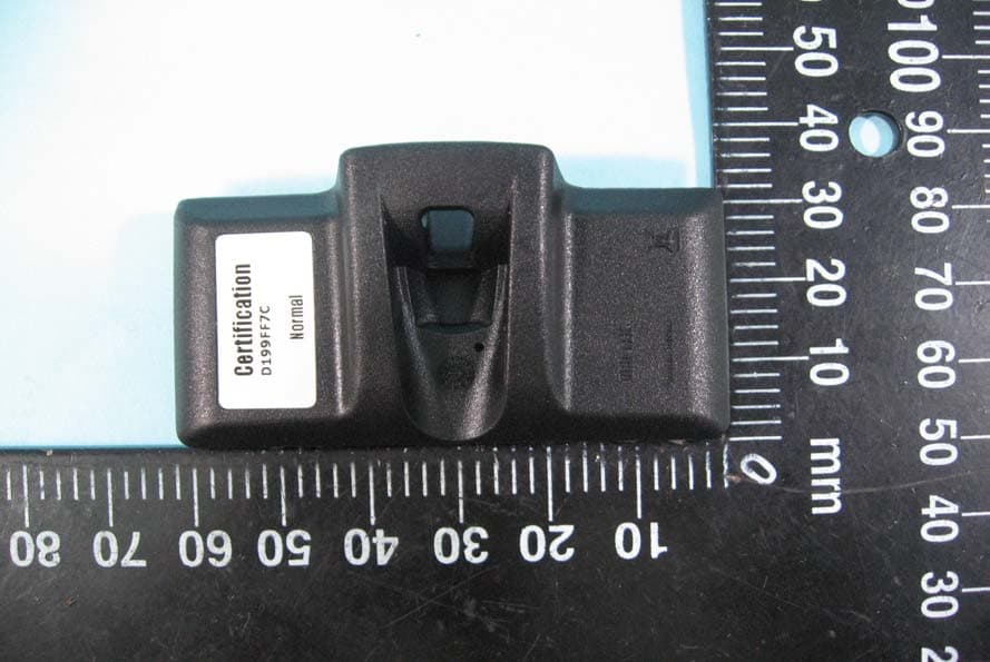
Click to zoom
Application Details
- Equipment Class
- DSC - Part 15 Security/Remote Control Transmitter
- Date of Grant
- Feb 08, 2011
- Application Purpose
- Original Equipment
- Date of Application
- Feb 08, 2011
- Equipment Note
- Tire Pressure Monitor System
- Frequency Range
- 433.92000000 - 433.92000000
- Company
- ORO-TEK CO., LTD.
- Country
- Taiwan
Documents & Files
Document Text
Text extracted from the exhibit documents filed with the FCC. Open a document above to read the original.
Users Manual
INSTALLATION INSTRUCTIONS Tire Pressure Monitor System (TPMS) Sensor Assemblies WARNING Read all instructions and warnings before installation. Refer to Mitchell Manual for installation specifications (excluding Ford Banded Sensors). Professional installation only. These Tire Pressure Monitor System Sensor assemblies are replacement or maintenance parts for motor vehicles that have a factory installed Tire Pressure Monitoring System (TPMS). Caution Each TPMS sensor is designed and manufactured to operate in a specific motor vehicle year, make and model, using the proper frequencies to communicate with the motor vehicle TPMS system. Only install TPMS sensors designated for your specific motor vehicle year, make, and model. Improper installation will cause the motor vehicle TPMS system to fail to operate properly. Do not install sensors in damaged wheels. Upon completion of installation, test the motor vehicle TPMS system using procedures described in Mitchell1 Manual (excluding Ford Banded Sensors) to confirm proper installation. If the TPMS system fails to operate properly, check all installation procedures to ensure proper installation and retest. If the TPMS system continues to fail to operate, immediately consult with an authorized motor vehicle dealership. If the OEM equipment wheels or tires are not used it is the responsibility of the vehicle owner to ensure that the TPMS system is functioning properly. The vehicle owner expressly assumes sole and complete responsibility for the TPMS and vehicle function if the OEM equipment wheels and tires are not used. Failure to ensure that the TPMS system is functioning properly can result in severe injury or death. It is MANDATORY to replace the sensor if it is externally damaged. WARNING FAILURE TO FOLLOW INSTRUCTIONS OR THE USE OF IMPORPER TPMS SENSORS MAY RESULT IN THE MOTOR VEHCILE TPMS FAILURE CAUSING POPERTY DAMDAGE PERSONAL INJURY OR DEATH. OERSX2 Sensor Specification Sensor’s Specification Battery life 8yearsnormallyuse. Battery Voltage 3.0V Storage Temperature -50°Cto150°C Operation Temperature -40°Cto125°C Operation Frequency 433.92MHz TransmissionFrequency Transmit1signaleach30sec. Pressure Monitoring Range 0~800kPa Pressure Reading Accuracy ±10kPa TemperatureMonitoring Range-50°Cto125°C TemperatureReading Accuracy ±4°C Notice : The changes or modifications not expressly approved by the party responsible for compliance could void the user’s authority to operate the equipment. IMPORTANT NOTE: To comply with the FCC RF exposure compliance requirements, no change to the antenna or the device is permitted. Any change to the antenna or the device could result in the device exceeding the RF exposure requirements and void user’s authority to operate the device.
External Photos
ETC Report No.:10-12-RBF-042-01 Sheet 1 of 5 Sheets FCC ID.: XB4OERSX2BCD Rev. No 1.0 CONSTRUCTED PHOTOS of EUT 1. Top View of EUT 2. Front View of EUT ETC Report No.:10-12-RBF-042-01 Sheet 2 of 5 Sheets FCC ID.: XB4OERSX2BCD Rev. No 1.0 CONSTRUCTED PHOTOS of EUT 3. Side View of EUT 4. Rear View of EUT ETC Report No.:10-12-RBF-042-01 Sheet 3 of 5 Sheets FCC ID.: XB4OERSX2BCD Rev. No 1.0 CONSTRUCTED PHOTOS of EUT 5. Side View of EUT 6. Bottom View of EUT
ID Label/Location Info
Lable Drawing FCC ID : XB4OERSX2BCD ORO-TEK OERSX2
Internal Photos
ETC Report No.:10-12-RBF-042-01 Sheet 4 of 5 Sheets FCC ID.: XB4OERSX2BCD Rev. No 1.0 CONSTRUCTED PHOTOS of EUT 7. Internal View of EUT ETC Report No.:10-12-RBF-042-01 Sheet 5 of 5 Sheets FCC ID.: XB4OERSX2BCD Rev. No 1.0 CONSTRUCTED PHOTOS of EUT 8. Component View of PCB 9. Solder View of PCB
Test Report
Rev. No 1.0 FCC Part 15 EMI TEST REPORT of E.U.T. : Tire Pressure Monitor System FCC ID : XB4OERSX2BCD MODEL : OERSX2 Workin g Frequency : 433.92 MHz for APPLICANT : ORO-TEK CO., LTD ADDRESS : 1F., NO.21, LN. 510, JHONGJHENG RD., FONGYUAN CITY, TAICHUNG COUNTY 42059, TAIWAN Test Performed by ELECTRONICS TESTING CENTER, TAIWAN NO.34, LIN 5, DINGFU TSUEN, LINKOU SHIANG TAIPEI COUNTY, TAIWAN, 24442, R.O.C. TEL : (02)26023052 Fax : (02)26010910 http://www.etc.org.tw ; e-mail: [email protected] Report Number : 10-12-RBF-042-01 ETC Report No.10-12-RBF-042-01 FCC ID.: XB4OERSX2BCD Rev. No 1.0 TEST REPORT CERTIFICATION Applicant : ORO-TEK CO., LTD 1F., NO.21, LN. 510, JHONGJHENG RD., FONGYUAN CITY, TAICHUNG COUNTY 42059, TAIWAN Manufacturer : ORO-TEK CO., LTD 1F., NO.21, LN. 510, JHONGJHENG RD., FONGYUAN CITY, TAICHUNG COUNTY 42059, TAIWAN Description of EUT : a) Type of EUT : Tire Pressure Sensor b) Trade Name : ORO-TEK c) Model No. : OERSX2 d) FCC ID : XB4OERSX2BCD e) Working Frequency : 433.92 MHz f) Power Supply : DC 3V Regulation Applied : FCC Rules and Regulations Part 15 Subpart C (2009) I HEREBY CERTIFY THAT; The data shown in this report were made in accordance with the procedures given in ANSI C63.4 (2003) and the energy emitted by the device was founded to be within the limits applicable. I assume full responsibility for accuracy and completeness of these data. Note : 1. The results of the testing report relate only to the items tested. 2. The testing report shall not be reproduced except in full, without the written approval of ETC. Issued Date : Jan. 17, 2011 Test Engineer : ( Vincent Chang, Engineer ) Check By : ( Charles Wang, Supervisor ) Approve & Authorized Signer : Will Yauo, Manager EMC Dept. II of ELECTRONICS TESTING CENTER, TAIWAN ETC Report No.10-12-RBF-042-01 FCC ID.: XB4OERSX2BCD Rev. No 1.0 Table of Contents Page 1. GENERAL INFORMATION ............................................................................................................................... 1 1.1 PRODUCT DESCRIPTION........................................................................................................................................... 1 1.2 CHARACTERISTICS OF DEVICE:................................................................................................................................ 1 1.3 TEST METHODOLOGY.............................................................................................................................................. 1 1.4 TEST FACILITY........................................................................................................................................................ 1 2. DEFINITION AND LIMITS ................................................................................................................................ 2 2.1 DEFINITION............................................................................................................................................................. 2 2.2 RESTRICTED BANDS OF OPERATION........................................................................................................................ 2 2.3 LIMITATION............................................................................................................................................................. 2 2.4 LABELING REQUIREMENT........................................................................................................................................ 4 2.5 USER INFORMATION................................................................................................................................................ 4 3 SYSTEM TEST CONFIGURATION ................................................................................................................... 5 3.1 JUSTIFICATION........................................................................................................................................................ 5 3.2 DEVICES FOR TESTED SYSTEM................................................................................................................................5 4. RADIATED EMISSION MEASUREMENT ...................................................................................................... 6 4.1 APPLICABLE STANDARD.......................................................................................................................................... 6 4.2 MEASUREMENT PROCEDURE................................................................................................................................... 6 4.3 TEST DATA.............................................................................................................................................................. 8 4.4 FIELD STRENGTH CALCULATION........................................................................................................................... 10 4.5 ACTIVATE TIME.................................................................................................................................................... 10 4.6 CALCULATION OF DUTY FACTOR.......................................................................................................................... 10 4.7 RADIATED TEST EQUIPMENT................................................................................................................................. 14 4.8 MEASURING INSTRUMENT SETUP.......................................................................................................................... 14 4.9 RADIATED MEASUREMENT PHOTOS...................................................................................................................... 15 5. BANDWIDTH OF EMISSION........................................................................................................................... 16 5.1 APPLICABLE STANDARD PLOT GRAPHIC OF BANDWIDTH.......................................................................…
Text truncated - open the document above for the full version.
Test Setup Photos
ETC Report No.:10-12-RBF-042-01 Sheet 16 of 20 Sheets FCC ID.: XB4OERSX2BCD Rev. No 1.0 4.9 Radiated Measurement Photos
Contact Information
Applicant
Max Chen(Manager)
Test Firm
Taiwan Testing and Certification CenterAnderson Ku
Technical Specifications
| # | Rule Parts | Frequency Range | Power Output |
|---|---|---|---|
| 1 | 15.231(e) | 433.92 MHz - 433.92 MHz | - |
Other Applications from ORO-TEK CO., LTD.
XB4OERSPT1
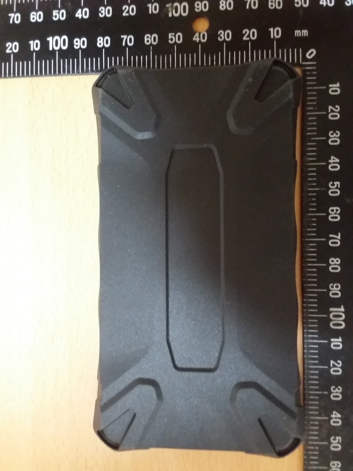
Nov 30, 2020Tire pressure sensor Tool
Equipment Class
DCD - Part 15 Low Power Transmitter Below 1705 kHz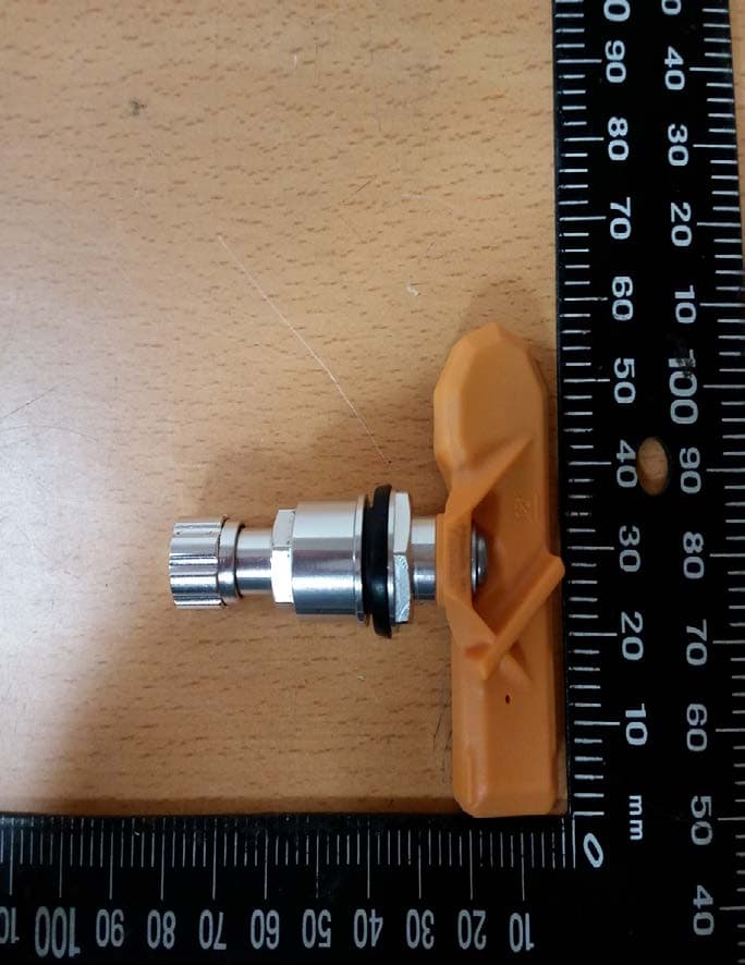
XB4OERS2B1
Nov 30, 2020Tire pressure sensor
Equipment Class
DSC - Part 15 Security/Remote Control TransmitterXB4OERSX3CEB
Jul 03, 2014Tire Pressure Sensor
Equipment Class
DSC - Part 15 Security/Remote Control Transmitter
XB4OERSX4BCD
Jul 03, 2014Tire Pressure Sensor
Equipment Class
DSC - Part 15 Security/Remote Control Transmitter