XBK-103RDigital camcorder remote control
Pro4Tech Ltd.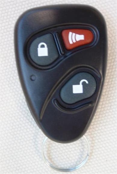
Click to zoom
Application Details
- Equipment Class
- DSR - Part 15 Remote Control/Security Device Transceiver
- Date of Grant
- Jan 04, 2010
- Application Purpose
- Original Equipment
- Date of Application
- Jan 04, 2010
- Equipment Note
- Digital camcorder remote control
- Frequency Range
- 868.00000000 - 868.00000000
- Company
- Pro4Tech Ltd.
- Country
- Israel
Documents & Files
Document Text
Text extracted from the exhibit documents filed with the FCC. Open a document above to read the original.
Users Manual
User Guide Pro4Tech © 2009 3 NanoPen User Guide Table of Content Introduction................................................................4 PC Minimum Requirements......................................... 4 Box Contents.............................................................5 Parts and Control.......................................................6 Closed View................................................................ 6 Open View.................................................................. 7 Remote Control Reference...........................................8 Function Table.............................................................9 Getting Started..........................................................10 Pen..............................................................................11 Opening and Closing...................................................11 Power On/Off..............................................................11 Charging.....................................................................12 Memory Availability.....................................................13 Battery Level................................................................13 Writing........................................................................14 Changing the Ink Cartridge.........................................14 Remote Control..........................................................15 Locking and Unlocking................................................15 Charging.....................................................................16 Video and Audio Recording.........................................17 Audio only Recording..................................................18 Taking a Snapshot.......................................................19 Indications...................................................................20 PC Functions...............................................................21 File Management.........................................................21 Disconnecting the NanoPen.........................................22 NanoPen Manager.....................................................23 Synchronizing Date and Timestamp.............................25 Formatting the NanoPen Memory................................27 Updating the NanoPen Firmware.................................28 Pairing and Un-Pairing.................................................30 Care and Maintenance...............................................32 Troubleshooting.........................................................33 Technical Specification...............................................34 Warranty.....................................................................35 FCC Compliance..........................................................36 4 NanoPen User Guide Introduction NanoPen is a self-contained covert digital camcorder concealed inside a fully functioning standard profile ballpoint pen. The pen has a hidden camera, microphone and micro-USB socket. The camera records events, incidents and the persons concerned. This is supplemented by an audio recording. If required, an audio only recording can be selected, and still images can be taken at any time. The pen can be either carried or concealed in worn clothing, with due care taken not to obstruct the camera lens or microphone. The pen can also be left unattended if required, and will still function normally. The Pen is operated remotely and covertly, using a remote control, disguised as normal car key fob. All NanoPen files are time and date stamped and stored in the internal flash memory in the following formats: Movie = MPEG4 (QVGA 320 x 240) • Audio Only = AMR• Snapshots = JPEG, UXGA (2M Pixels)• All NanoPen digital files are exported by Micro-USB and are easily viewed, renamed, edited and transferred using Windows© Explorer. PC Minimum Requirements USB 1.1 or higher• Windows 2000/XP/Vista• QuickTime Player• 5 NanoPen User Guide Box Contents NanoPen1. Remote Control key fob2. Multi-Charger3. USB Cable4. Spare ink refills5. User Guide6. Reference Card7. Carrying Case8. 6 NanoPen User Guide Parts and Control Closed View This view shows the pen in its normal state. Lens location (do not obscure) 1. Microphone location (do not block)2. Nib3. 2 1 3 7 NanoPen User Guide Open View This view shows the pen in its open state. All components listed here, are concealed when the pen is closed. Power on/off button 1. LEDs indicators2. Micro-USB socket 3. 3 1 2 8 NanoPen User Guide Remote Control Reference This view shows the remote control. Lock button (Taking snapshot) 1. Alarm button (Audio only recording)2. LED3. indicator Unlock button (A/V recording)4. S5. ocket cover Micro-USB socket 6. 4 3 2 1 6 5 9 NanoPen User Guide Function Table FunctionPress Vibration (Remote) Remote Control LEDs NanoPen LEDs Ref. Page Power On Power Button Five times 11 Off Power Button Twice Lock Locking + Four times Four times 15 Unlocking + TwiceTwice Audio/Video BeginOnceOnce Memory level indication 17 EndAnyTwiceTwiceTwice Audio Only BeginOnceOnce Battery level indication 18 EndAnyTwiceTwiceTwice Take snapshots TwiceTwiceTwice19 10 NanoPen User Guide Getting Started When you get the NanoPen, check that the box contents are complete, and undamaged. Also take time to read the instructions and familiarize yourself with the basic functions. Then take the following action Charge the NanoPen using the process described on 1. page 13. Charging process can take up to 3 hours. Charge the Remote Control using the process described 2. on page 16. Adjust the time stamp using the process described 3. on page 25. WARNING: The NanoPen must only be formatted using the procedure and software described on page 27. Failure to do this will result in irreparable damage. 11 NanoPen User Guide Pen Opening and Closing To locate the power button and the Micro-USB socket, as shown on open view picture (page 7), take the pen in both hands and pull gently on each…
Text truncated - open the document above for the full version.
Attestation Statements
Attestation_letter_19509_RC.doc January 4, 2010 To: Telefication B.V. Attn: Dept. FCC TCB Edisonstraat 12A 6902 PK ZEVENAAR The Netherlands Subject: Revised documents for Application for certification of a digital camcorder remote control, FCC ID:XBK-103R Dear Gentlemen, Owing to the changes performed by applicant in the remote control for the marketing purposes the device re-testing was performed and a new test report was issued. The functionality of the product has no change. The following changes were performed in the device: 1) the battery was changed from a disposable one to a rechargeable Li Ion battery; 2) the charging is done by a standard micro USB connector, the device enclosure was changed; the improved enclosure contains a covered slot (by a silicon shutter) for the micro USB connector 3) The connection to a PC is only for charging and there is no data transfer. We submit the corresponding documentation: 1) Test report PRORAD_FCC.20255_RC 2) Schematic_diagram_19509_RC_rev1 3) External_photos_19509_RC_rev1 4) Internal_photos_19509_RC_rev1 5) Label_19509_RC_rev1 6) Product_description_19509_RC_rev1 7) Supplier_declaration_19509. We hope the application satisfies your requirements. Sincerely yours, Michael Nikishin, EMC and Radio group manager Hermon Labs P.O.Box 23 Binyamina 30500 Israel Tel. +972 4628 8001 Fax +972 4628 8277 Email: [email protected]
Cover Letter(s)
868MHz AntennaP/N 0868AT43A0020 Detail Specification: 06/06/07 Page 1 of 3 General Specifications Part Number0868AT43A0020Input Power3W max. Frequency Range858 - 878 MhzImpedance50 Ω Peak Gain-1.0 dBi typ. (XZ-total)Operating Temperature-40 to +85°C Average Gain-4.0 dBi typ. (XZ-total)Reel Quanity1,000 Return Loss9.5 dB min. MSL2 No.FunctionTerminal Configuration 1 2 Mechanical Dimensions Inmm L±± W±± T a±± Mounting Considerations Mount these devices with brown mark facing up. Units: mm * Line width should be designed to provide 50 Ω impedance matching characteristics. With Matching Circuit Johanson Technology, Inc. reserves the right to make design changes without notice. All sales are subject to Johanson Technology, Inc. terms and conditions. www.johansontechnology.com 4001 Calle Tecate • Camarillo, CA 93012 • TEL 805.389.1166 FAX 805.389.1821 2007 Johanson Technology, Inc. All Rights Reserved High Frequency Ceramic Solutions 0.0080.2767.000.20 0.80 0.0200.012 +0.1/-0.2 0.079 0.031 2.00 +.004/-.008 0.008 Feeding Point NC 0.20 0.500.30 12 L W a T JTI P/N for Matching Circuit: Cap (0.3pF): 500R07S0R3BV4T Cap (3.9pF): 500R07S3R9BV4T Inductor (18nH): L-07C18NJV6T * * * 2.0 5.5 8.0 1.0 5.0 7.0 3.0 5.0 0.5 0.3 pF 18 nH 3.9 pF Matching circuits 868MHz AntennaP/N 0868AT43A0020 Detail Specification: 06/06/07 Page 2 of 3 Mounting Considerations Test Board Johanson Technology, Inc. reserves the right to make design changes without notice. All sales are subject to Johanson Technology, Inc. terms and conditions. www.johansontechnology.com 4001 Calle Tecate • Camarillo, CA 93012 • TEL 805.389.1166 FAX 805.389.1821 2007 Johanson Technology, Inc. All Rights Reserved High Frequency Ceramic Solutions ) ) ) ) ) ) ) ) ) Antenna Ground 20mm 40mm9.5mm 50Ω Feed Line Return Loss (with matching) Antenna No Ground Ground 20mm 19mm 40mm 9.5mm 50Ω Feed Line 868MHz AntennaP/N 0868AT43A0020 Detail Specification: 06/06/07 Page 3 or 3 Johanson Technology, Inc. reserves the right to make design changes without notice. All sales are subject to Johanson Technology, Inc. terms and conditions. www.johansontechnology.com 4001 Calle Tecate • Camarillo, CA 93012 • TEL 805.389.1166 FAX 805.389.1821 2007 Johanson Technology, Inc. All Rights Reserved High Frequency Ceramic Solutions ) ) ) ) ) ) ) ) ) Typical Radiation Patterns ) ) ) ) ) ) ) ) ) XY-V/XY-H 180° 270° 0° 90° X Z Y XY-cut scanning direction XY cut @868MHz Vertical Horizontal XZ-V/XZ-H YZ-V/YZ-H 180° 270° 0° 90° X Z Y XZ-cut scanning direction 180° 270° 0° 90° X Z Y YZ-cut scanning direction YZ cut @868MHz Vertical Horizontal XZ cut @868MHz Vertical Horizontal
Cover Letter(s)
July 16, 2009 To: Telefication B.V. Attn: Dept. FCC TCB Edisonstraat 12A 6902 PK ZEVENAAR The Netherlands Subject: Application for certification of a digital camcorder remote control, FCC ID:XBK-103R Dear Gentlemen, Please find attached our application for certification of a digital camcorder remote control, FCC ID:XBK-103R, prepared in accordance with FCC Rules, part 2 and part 15 subpart C, section 15.231. The product testing and this application for certification were performed by Hermon Laboratories, which is listed by FCC, Registration Numbers 90623, 90624. Hermon Labs responsible person is Mr. Michael Nikishin, tel: 011 972 4626 8440, fax:011 972 4628 8277, e-mail: [email protected] . Please send an invoice to Hermon Labs. Product manager
Cover Letter(s)
1 | P a g e Declaration of Authorization We Name: Pro4Tech Ltd. Address: Kochav Yokneam Bldg. 5th fl., P.O.Box 607 City: Yokneam ................................................. Country: Israel........................................... Declare that: Name Representative of agent: ////. Agent Company name: Hermon Laboratories Ltd. Address: Harakevet Industrial Zone City: Binyamina 30500 Country Israel ............. is authorized to apply for Certification of the following product(s): Product description: Pen & Remote Control Type designation: MVC103P ; MVC103R Trademark: NanoPen on our behalf. Date: June 14, 2009 City: Yokneam Name: Yaniv Ben Yohana Function: Product Manager Signiture:
Cover Letter(s)
FCC, Request for non-disclosure Date: 6/14/2009 RF_501, Issue 3 Page 1 of 1 To: Telefication B.V. Attn: Dept. FCC TCB Edisonstraat 12A 6902 PK ZEVENAAR The Netherlands Subject: Request for confidentiality FCC ID: XBK-103R Reference number: ###### Dear FCC TCB, Pursuant to 47 CFR Section 0.459(a) & (b), PRO4TECH hereby requests non-disclosure and confidential treatment of the following materials submitted in support of FCC certification application for FCC ID: XBK-103R Block Diagrams Operational Description Schematic Diagrams Above materials contain secrets, proprietary and technical information, which would customarily be quarded from competitors under 47 CFR, section 0.457(d)(2). Disclosure or publication or any portion of this company confidential material to other parties could cause substantial competitive harm and provide unjustified benefits for competitors. PRO4TECH understands that pursuant to 47 CFR section 0.457(d)(1)(ii) disclosure of the applicant and all accompanying documentation will not be made before the date of the grant. 14/06/2009 Yokneam Illit Yaniv Ben Yohana
Cover Letter(s)
Supplier declaration for a NanoPen digital camcorder pen and remote control We declare that Digital camcorder pen MVC103P and Digital camcorder remote control MVC103R comply with the FCC part 15 subpart C section 15.231(a) standard requirements: 1) Continuous transmissions are not permitted; 2) Periodic transmissions at regular predetermined intervals are not permitted. Sincerely, Product manager
External Photos
Pro4Tech Ltd. FCC ID:XBK-103R External_photos_19509_RC_rev1.doc Page 1 of 4 EXTERNAL PHOTOGRAPHS This document contains 3 photographs Pro4Tech Ltd. FCC ID:XBK-103R External_photos_19509_RC_rev1.doc Page 2 of 4 Photograph No.1 NanoPen Remote Control front view Pro4Tech Ltd. FCC ID:XBK-103R External_photos_19509_RC_rev1.doc Page 3 of 4 Photograph No.2 NanoPen Remote Control rear side view Pro4Tech Ltd. FCC ID:XBK-103R External_photos_19509_RC_rev1.doc Page 4 of 4 Photograph No.3 NanoPen Remote Control side view
ID Label/Location Info
Page 1 of 1 FCC ID:XBK-103R Label The label shown below is affixed on the rear side of the camcorder remote control. The label material is PVC with a permanent adhesive. Label location Label with FCC ID:XBK-103R location FCC ID:XBK-103R
Internal Photos
Pro4Tech Ltd. FCC ID:XBK-103R Internal_photos_19509_RC_rev1.doc Page 1 of 6 INTERNAL PHOTOGRAPHS This document contains 5 photographs Pro4Tech Ltd. FCC ID:XBK-103R Internal_photos_19509_RC_rev1.doc Page 2 of 6 Photograph No.1 NanoPen Remote Control internal view Pro4Tech Ltd. FCC ID:XBK-103R Internal_photos_19509_RC_rev1.doc Page 3 of 6 Photograph No.2 NanoPen Remote Control rear side view Pro4Tech Ltd. FCC ID:XBK-103R Internal_photos_19509_RC_rev1.doc Page 4 of 6 Photograph No.3 Remote Control PCB front view Pro4Tech Ltd. FCC ID:XBK-103R Internal_photos_19509_RC_rev1.doc Page 5 of 6 Photograph No.4 Remote Control PCB rear side view Pro4Tech Ltd. FCC ID:XBK-103R Internal_photos_19509_RC_rev1.doc Page 6 of 6 Photograph No.5 Remote Control PCB side view
Test Report
Hermon Laboratories Ltd. Harakevet Industrial Zone, Binyamina 30500, Israel Tel. +972-4-6288001 Fax. +972-4-6288277 E-mail: [email protected] Page 1 of 47 Report ID: PRORAD_FCC.20255_RC.doc Date of Issue: 12/23/2009 Electrical 839.01 TEST REPORT ACCORDING TO: FCC CFR 47 PART 15 subpart C, section 15.231(a) and subpart B FOR: Pro4Tech Ltd. Digital camcorder remote control Brand name: NanoPen Model: MVC103R This report is in conformity with ISO/ IEC 17025. The "A2LA Accredited" symbol endorsement applies only to the tests and calibrations that are listed in the scope of Hermon Laboratories accreditation. The test results relate only to the items tested. This test report shall not be reproduced in any form except in full with the written approval of Hermon Laboratories Ltd. Report ID: PRORAD_FCC.20255_RC.doc Date of Issue: 12/23/2009 Page 2 of 47 Table of contents 1 Applicant information..................................................................................................................................................... 3 2 Equipment under test attributes .................................................................................................................................... 3 3 Manufacturer information .............................................................................................................................................. 3 4 Test details.................................................................................................................................................................... 3 5 Tests summary.............................................................................................................................................................. 4 6 EUT description............................................................................................................................................................. 5 6.1 General information....................................................................................................................................................... 5 6.2 Changes made in EUT .................................................................................................................................................. 7 6.3 Transmitter characteristics ............................................................................................................................................ 7 7 Transmitter tests according to 47CFR part 15 subpart C requirements ........................................................................ 8 7.1 Periodic operation requirements ................................................................................................................................... 8 7.2 Field strength of emissions.......................................................................................................................................... 11 7.3 Occupied bandwidth test ............................................................................................................................................. 29 7.4 Antenna requirements ................................................................................................................................................. 31 8 Unintentional emission tests........................................................................................................................................ 32 8.1 Radiated emission measurements .............................................................................................................................. 32 9 APPENDIX A Test equipment and ancillaries used for tests....................................................................................... 38 10 APPENDIX B Measurement uncertainties................................................................................................................... 39 11 APPENDIX C Test laboratory description ................................................................................................................... 40 12 APPENDIX D Specification references ....................................................................................................................... 40 13 APPENDIX E Test equipment correction factors......................................................................................................... 41 14 APPENDIX F Abbreviations and acronyms................................................................................................................. 47 Report ID: PRORAD_FCC.20255_RC.doc Date of Issue: 12/23/2009 Page 3 of 47 1 Applicant information Client name: Pro4Tech Ltd. Address: Kochav-Yokneam Bldg. 5th fl., P.O.Box 607, Yokneam 20692, Israel Telephone: +972 4959 0081 Fax: +972 4989 0480 E-mail: [email protected] Contact name: Mr. Eli Yarkoni 2 Equipment under test attributes Product name: Digital camcorder remote control Product type: Transceiver Brand name: NanoPen Model(s): MVC103R Receipt date 11/29/2009 3 Manufacturer information Manufacturer name: Pro4Tech Ltd. Address: Kochav-Yokneam Bldg. 5th fl., P.O.Box 607, Yokneam 20692, Israel Telephone: +972 4959 0081 Fax: +972 4989 0480 E-Mail: [email protected] Contact name: Mr. Eli Yarkoni 4 Test details Project ID: 20255 Location: Hermon Laboratories Ltd. Harakevet Industrial Zone, Binyamina 30500, Israel Test started: 11/29/2009 Test completed: 12/07/2009 Test specification(s): FCC Part 15, subpart C, §15.231(a); subpart B, §15.109 Report ID: PRORAD_FCC.20255_RC.doc Date of Issue: 12/23/2009 Page 4 of 47 5 Tests summary Test Status Transmitter characteristics Section 15.231(a), Periodic operation requirements Pass Section 15.231(b), Field strength of emissions Pass Section 15.231(c), Occupied bandwidth Pass Section 15.207(a), Conducted emission Not required Section 15.203, Antenna requirement Pass Unintentional emissions Section 15.109, Radiated emission Pass Testing was completed against all relev…
Text truncated - open the document above for the full version.
Test Setup Photos
Pro4Tech Ltd. FCC ID: XBK-103R Page 1 of 10 SETUP PHOTOGRAPHS This document contains 9 photographs Pro4Tech Ltd. FCC ID: XBK-103R Page 2 of 10 Photograph No.1 Occupied bandwidth measurement setup Pro4Tech Ltd. FCC ID: XBK-103R Page 3 of 10 Photograph No.2 Spurious emissions measurement setup in the anechoic chamber below 30 MHz Pro4Tech Ltd. FCC ID: XBK-103R Page 4 of 10 Photograph No.3 Fundamental and spurious emissions measurement setup in the anechoic chamber in 30-1000 MHz range Pro4Tech Ltd. FCC ID: XBK-103R Page 5 of 10 Photograph No.4 Spurious emissions measurement setup in the anechoic chamber above 1000 MHz Pro4Tech Ltd. FCC ID: XBK-103R Page 6 of 10 Photograph No.5 Spurious emissions measurement setup in the anechoic chamber, EUT in X-axis orientation Pro4Tech Ltd. FCC ID: XBK-103R Page 7 of 10 Photograph No.6 Spurious emissions measurement setup in the anechoic chamber, EUT in Y-axis orientation Pro4Tech Ltd. FCC ID: XBK-103R Page 8 of 10 Photograph No.7 Spurious emissions measurement setup in the anechoic chamber, EUT in Z-axis orientation Pro4Tech Ltd. FCC ID: XBK-103R Page 9 of 10 Photograph No.8 Spurious emissions measurement setup above 1000 MHz at the OATS Pro4Tech Ltd. FCC ID: XBK-103R Page 10 of 10 Photograph No.9 Spurious emissions measurement setup above 1000 MHz at the OATS
Contact Information
Applicant
Yaniv Ben Yohana(Product Manager)
Technical Contact
Hermon Laboratories LTd.Michael Nikishin
[email protected]+97246268440
Harakevet Industrial zone · Binyamina · Israel
Test Firm
Hermon Laboratories Ltd.Alexander Usoskin
Technical Specifications
| # | Rule Parts | Frequency Range | Power Output |
|---|---|---|---|
| 1 | 15.231 | 868 MHz - 868 MHz | - |