XBL-TRANSCEIVERRadio repeater (V2.00) intended to be used for receiving and transmitting the cow tag signal
E.N.G.S Systems Ltd.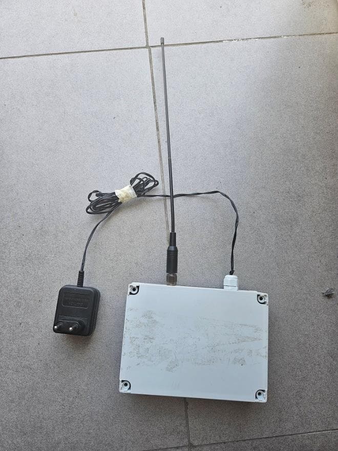
Click to zoom
Application Details
- Equipment Class
- DSC - Part 15 Security/Remote Control Transmitter
- Date of Grant
- Oct 06, 2023
- Application Purpose
- Original Equipment
- Date of Application
- Sep 26, 2023
- Equipment Note
- Radio repeater (V2.00) intended to be used for receiving and transmitting the cow tag signal
- Frequency Range
- 433.92000000 - 433.92000000
- Company
- E.N.G.S Systems Ltd.
- Country
- Israel
Documents & Files
Document Text
Text extracted from the exhibit documents filed with the FCC. Open a document above to read the original.
Users Manual
InstructionsforTransceiverinstallation: ** ThisequipmenthasbeentestedandfoundtocomplywiththelimitsforaClassBdigitaldevice, pursuanttopart15oftheFCCRules.Theselimitsaredesignedtoprovidereasonableprotectionagainst harmfulinterferenceinaresidentialinstallation.Thisequipmentgeneratesusesandcanradiateradio frequencyenergyand,ifnotinstalledandusedinaccordancewiththeinstructions,maycauseharmful interferencetoradiocommunications.However,thereisnoguaranteethatinterferencewillnotoccurina particularinstallation.Ifthisequipmentdoescauseharmfulinterferencetoradioortelevisionreception, whichcanbedeterminedbyturningtheequipmentoffandon,theuserisencouragedtotrytocorrectthe interferencebyoneormoreofthefollowingmeasures: ●Reorientorrelocatethereceivingantenna. ●Increasetheseparationbetweentheequipmentandreceiver. ●Connecttheequipmentintoanoutletonacircuitdifferentfromthattowhichthereceiveris connected. ●Consultthedealeroranexperiencedradio/TVtechnicianforhelp. E.N.G.SSystemsLTDisnotresponsibleforanyradioorcommunicationinterferencecausedbyusing otherthanspecifiedorrecommendedcablesandbatteryorbyunauthorizedchangesormodificationsto thisequipment.Changesormodificationsnotexpresslyapprovedbythemanufacturercouldvoidthe user’sauthoritytooperatetheequipment. Thisdevicecomplieswithpart15oftheFCCRules.Operationissubjecttothefollowingtwoconditions: 1.Thisdevicemaynotcauseharmfulinterference,and 2.Thisdevicemustacceptanyinterferencereceived,includinginterferencethatmaycauseundesired operation. InstallationlocationoftheTransceiverdependsonthefarmtopology,layoutofthe cowshed,distancebetweenshedsandfarm,andinterferingobjects. ThefollowingaregeneralguidelinestoconsiderwhenlocatingtheTransceiver. ConsultwithENGSSystemsLtdfordetailedguidelinesaboutthelocationandtypeof installation. ●Atcloseproximitytothetags-theTransceiverhasthestrongestsignal ●Atasufficientheight ●Avoidobstructionsofwalls,buildings,andmetalobjects. ●Awayfrommetalobjects Requiredparts: OptionalParts Polebracketsforpolemountingx2 Screwkitforpolemountingx2 InstallingtheTransceiver 1.Removethebackcover. 2.Insertthescrewsthroughthepre-madeholes. Asshown: 3.Assembletheboxbrackets,washers,andnutsonthescrewsandtighten. Asshown: 4.TomounttheTransceiveronapole,usetheoptionalpolebracketsandscrewkitfor polemountingas Asshown: InstallingaSolarPanel RequiredParts InstallingthePanel 1.ConnectthesolarbracketstotheS-shapedbracketsusingthescrewskitforsolar panelassemblyandassemblewashersandnuts. AsShown: 2.Assemblethesolarpanel:insertthebottomholderofthesolarpanelintotheslotof thesolarbracket.Pushdownthesolarpaneltothebottomofthebracket,theninsertthe topholderintotheslotofthesolarbracket. 3.Usethescrewkitforpanellockandinsertscrewsintotheholesattheedgeofeach bracket. Asshown 4.Assemblethewashersandnutsattheendofthescrewsandtighten.
Attestation Statements
Section 2.911(d)(5)(i) Certification – Equipment Type Company name: E.N.G.S Systems Address: Z.H.R Industrial Park Rosh-Pina Israel Product Name: Transceiver FCC ID: XBL-Transceiver Model(s): Transceiver V-2.00 2.911(d)(5)(i) Equipment Type We, E.N.G.S Systems (“the applicant”) certify that the equipment for which authorization is sought through certification is not: • Prohibited from receiving an equipment authorization pursuant to § 2.903; of the FCC rules. • Identified as an equipment type in the “Covered List” NOTE 1 Yours sincerely, Name: Eyal Fisher Date: 1/5/2023 Title and Company name: E.N.G.S Systems NOTE 1 “Covered List”; is the List of Equipment and Services Covered By Section 2 of The Secure Networks Act, available at https://www.fcc.gov/supplychain/coveredlist References; 1) 986446 D01 Covered Equipment v01 https://apps.fcc.gov/oetcf/kdb/forms/FTSSearchResultPage.cfm?switch=P&id=325672 2) Federal Register document 2022-28263 published on 02/06/23 https://www.federalregister.gov/documents/2023/02/06/2022-28263/protecting-against-national-security-threats-to-the- communications-supply-chain-through-the
Attestation Statements
Section 2.911(d)(5)(ii) Certification – Applicant (Covered List) Company name: E.N.G.S Systems Address: Z.H.R Industrial Park Rosh-Pina Israel Product Name: Transceiver FCC ID: XBL-Transceiver Model(s): Transceiver V-2.00 2.911(d)(5)(ii) Applicant filing We, E.N.G.S Systems (“the applicant”) certify that, as of the date of the filing of the application, the applicant is identified / is not identified NOTE 1 on the “Covered List” NOTE 2 , established pursuant to § 1.50002 of this chapter, as an entity producing covered communications equipment. Yours sincerely, Name: Eyal Fisher Date: 1/5/2023 Title and Company name: R&D Manager, E.N.G.S Systems NOTE 1 Delete option not applicable to this application. NOTE 2 “Covered List”; is the List of Equipment and Services Covered By Section 2 of The Secure Networks Act, available at https://www.fcc.gov/supplychain/coveredlist References; 1) 986446 D01 Covered Equipment v01 https://apps.fcc.gov/oetcf/kdb/forms/FTSSearchResultPage.cfm?switch=P&id=325672 2) Federal Register document 2022-28263 published on 02/06/23 https://www.federalregister.gov/documents/2023/02/06/2022-28263/protecting-against-national-security-threats-to-the- communications-supply-chain-through-the
External Photos
Transceiver External photos XBL-TRANSCEIVER
ID Label/Location Info
Transceiver XBL-TRANSCEIVER ID Label & Location info
Internal Photos
Transceiver XBL-TRANSCEIVER Internal photos
RF Exposure Info
RF exposure limit according to FCC CFR 47 parts 1 and 2 §1.310(e), §2.1091(b). According report 7212319860 of SII FCC ID: XBL-TRANSCEIVER FCC §1.1310 limit of power density for general population/uncontrolled exposure is 1 mW/cm 2 . The EUT is defined as module inside portable device designed to be used so that the radiating structure(s) of the device may be used at 20 centimeters distance from the body of the user. Pt- the transmitted maximum EIRP power = -23.48 dBm = 0.00448871 mW. Peak power density for distance 20 cm is Pt/4πr² = 0.00448871 mW/4π*20² = 8.93*10 -7 mW/cm². That is less than 1 mW/cm² power density limit.
Test Report
Test Report No. 7212319860 Applicant: E.N.G.S Systems LTD Equipment Under Test: RF transceiver Model: Radio repeater (V2.00) FCC ID: XBL-TRANSCEIVER The Standards Institution of Israel Industry Division Electrical & Electronics Laboratory EMC Branch Certificate Number:AT-1359 Test Report No.: 7212319860 Page 2 of 25 pages Title: RF transceiver Model: Radio repeater (V2.00) FCC ID: XBL-T RANSCEIVER Description of Equipment Under Test (EUT): Radio repeater (Transceiver) Model: Radio repeater (V2.00) Software version of radio unit: V-3.2.3 Hardware version of radio unit: V2.00 Manufactured by: E.N.G.S Systems LTD Reference Documents: CFR 47 FCC: Rules and Regulations; Part 15. “Radio frequency devices”; Subpart C: “Intentional radiators” Section 15.205. “Restricted bands of operations”, Section 15.207. “Conducted limits” Section 15.209. “Radiated emission limits, general requirements”. “Radiated Emission Limits, Additional Provisions”; Section 15.231. “Periodic operation in the bands 40.66 – 40.70 MHz, and above 70 MHz”. . Applicant: E.N.G.S Systems LTD Address: ZAHAR industrial park, POB 666, Rosh-Pina , Israel Sample for test selected by: The customer The date of tests: 29 September 2022 - 3 November 2022 This Test Report contains 25 pages and may be used only in full. This Test Report applies only to the specimen tested and may not be applied to other specimens of the same product. Test Report No.: 7212319860 Page 3 of 25 pages Title: RF transceiver Model: Radio repeater (V2.00) FCC ID: XBL-T RANSCEIVER Table of Contents 1. EUT Description and operation 4 1.1. General description: 4 2. Test summary 5 2.1. EUT setup and operation: 7 3. Measurements and derived results 7 3.1. Location of the Test Site: 7 3.2. Test condition: 7 3.3. Radiated emission test. 8 3.4. Common conditions for operation in the band above 70 MHz. 9 3.5. Test of field strength emission from intentional radiator. 10 3.6. Transmission activation. 14 3.7. Test of occupied bandwidth per 15.231(c) 15 3.8. Conducted emissions test per 15.207(a) 16 3.9. Antenna requirement 19 4. Appendix 1: Test equipment used 21 5. Appendix 2: Antenna Factor and Cable Loss 22 6. Appendix 3: Test setups photo. 25 Test Report No.: 7212319860 Page 4 of 25 pages Title: RF transceiver Model: Radio repeater (V2.00) FCC ID: XBL-T RANSCEIVER 1. EUT Description and operation 1.1. General description: * Note: the customer supplied all information in clause below. The Equipment Under Test (hereinafter: EUT) is a Radio repeater Model Radio repeater (V2.00) intended to be used for receiving and transmitting the cow tag signal. Radio repeater works in the transmitting at 433.9MHz. Radio repeater works with the 24 Volt AC. The tag is attached to a belt and worn around the neck or leg of a cow. The main future of the Transceiver is to receive and transmit the cow tag data. A Cow tags used for Cow monitoring. The tag is counting steps and monitor cow behavior. Type of modulation: FSK Antenna type: Omni. Antenna gain 2.15 dBi. Manufacturer: HYS Model number: 433-RH771-BNC The EUT external view is presented in photo 1. Photo 1. Transceiver view and block diagram. Test Report No.: 7212319860 Page 5 of 25 pages Title: RF transceiver Model: Radio repeater (V2.00) FCC ID: XBL-T RANSCEIVER 2. Test summary Parameter FCC Part 15 Reference paragraph Verdict Radiated emission from intentional radiators in restricted bands Subpart C Section 15.205 Comply AC line conducted emission test Subpart C Section 15.207 Comply Test of field strength emission from intentional radiators “Radiated Emission Limits, Additional Provisions”; Section 15.231. Comply Occupied bandwidth Subpart C section 15.231(c) Comply Electrical & Electronics Laboratory 17 July 2023 Name: Eng. Yuri Rozenberg Name: Alexander Konkov Position: Head of Branch Position: Test Engineer Measurement uncertainty. The test equipment has been calibrated according to its recommended procedures and is within the manufacturer's published limit of error. The laboratory calibrates its standards by a third party (traceable to NIST, USA) on a regular basis according to equipment manufacturer requirements. In the following table the uncertainty calculation is given. Type of disturbance Test description Calculated uncertainty U LAB Radiated disturbance electric field strength in a SAR at 3 m distance 30 MHz – 1.0 GHz ±4.32 dB electric field strength in a FAR at 3 m distance 1.0 – 18 GHz. 18 – 40 GHz. ±4.47 dB ±2.78 dB Test Report No.: 7212319860 Page 6 of 25 pages Title: RF transceiver Model: Radio repeater (V2.00) FCC ID: XBL-TRANSCEIVER Normative References. FCC 47 CFR Part 15, Subpart C Radio Frequency Devices Subpart C – Intentional Radiators ANSI C63.4: 2009 American National Standard for Method of Measurements of Radio-Noise Emissions from Low-Voltage Electrical and Electronic Equipment in the Range of 9 kHz to 40 GHz ANSI C63.10: 2013 American National Standard of Procedures for Compliance Testing of Unlicensed Wireless Devices. Test Report No.: 7212319860 Page 7 of 25 pages Title: RF transceiver Model: Radio repeater (V2.00) FCC ID: XBL-TRANSCEIVER 2.1. EUT setup and operation: Test was performed in continuous transmission mode. The transmitter operated in test mode and transmitted a modulated FSK signal with a random transmission of zero or one. 3. Measurements and derived results 3.1. Location of the Test Site: Radiated test measurements were conducted in the Anechoic chamber at the EMC laboratory of the Standards Institution of Israel in Tel-Aviv. 3.2. Test condition: Temperature: 24 °C. Humidity: 53 %. Atmospheric pressure: 1010 mbar. Test Report No.: 7212319860 Page 8 of 25 pages Title: RF transceiver Model: Radio repeater (V2.00) FCC ID: XBL-T RANSCEIVER 3.3. Radiated emission test. 3.3.1. General: Per FCC Part 15 Subpart C Sections 15.209, 15.231. Initial scans were made using a peak detector but still using the appropriate ANSI IF bandwidth. 3.3.2. Radiated emission measurements: Preliminary investigatio…
Text truncated - open the document above for the full version.
Test Setup Photos
Test set up photos. FCC ID: XBL-TRANSCEIVER Radiated emissions test set up below 30MHz. Radiated emissions test set up in 30MHz-1GHz frequency range Radiated emissions test set up above 1GHz. Radiated emissions test set up above 1GHz on table.
Contact Information
Applicant
Eyal Fisher(Electronics engineer)
Technical Contact
Test Firm
Electrical and Electronics laboratory, SIIAlbert Herzenshtein
[email protected](972)-3-646-5069
Technical Specifications
| # | Rule Parts | Frequency Range | Power Output |
|---|---|---|---|
| 1 | 15.231 | 433.92 MHz - 433.92 MHz | - |
Other Applications from E.N.G.S Systems Ltd.
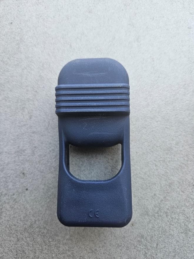
XBL-NECKTAG
Oct 06, 2023Cow Neck Tag intended to be used in a farm shed and in the parlor
Equipment Class
DSC - Part 15 Security/Remote Control Transmitter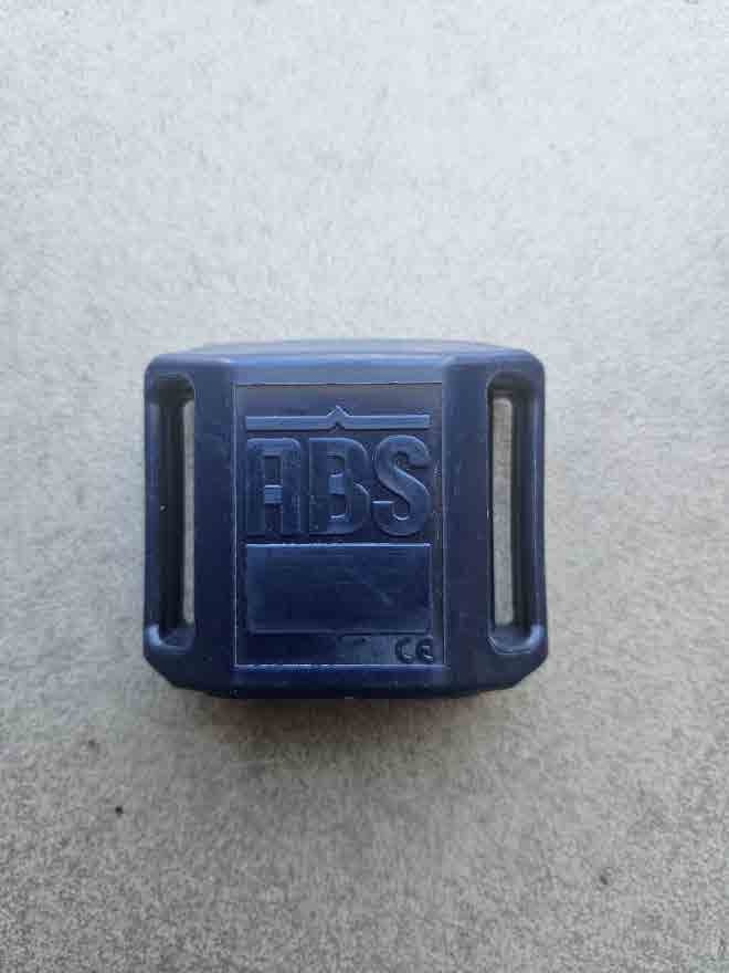
XBL-LEGTAG
Oct 06, 2023Cow Leg Tag intended to be used in a farm shed and in the parlor
Equipment Class
DSC - Part 15 Security/Remote Control Transmitter