XCU21022100 Series Scoring equipment for Fencing
Hitmate Limited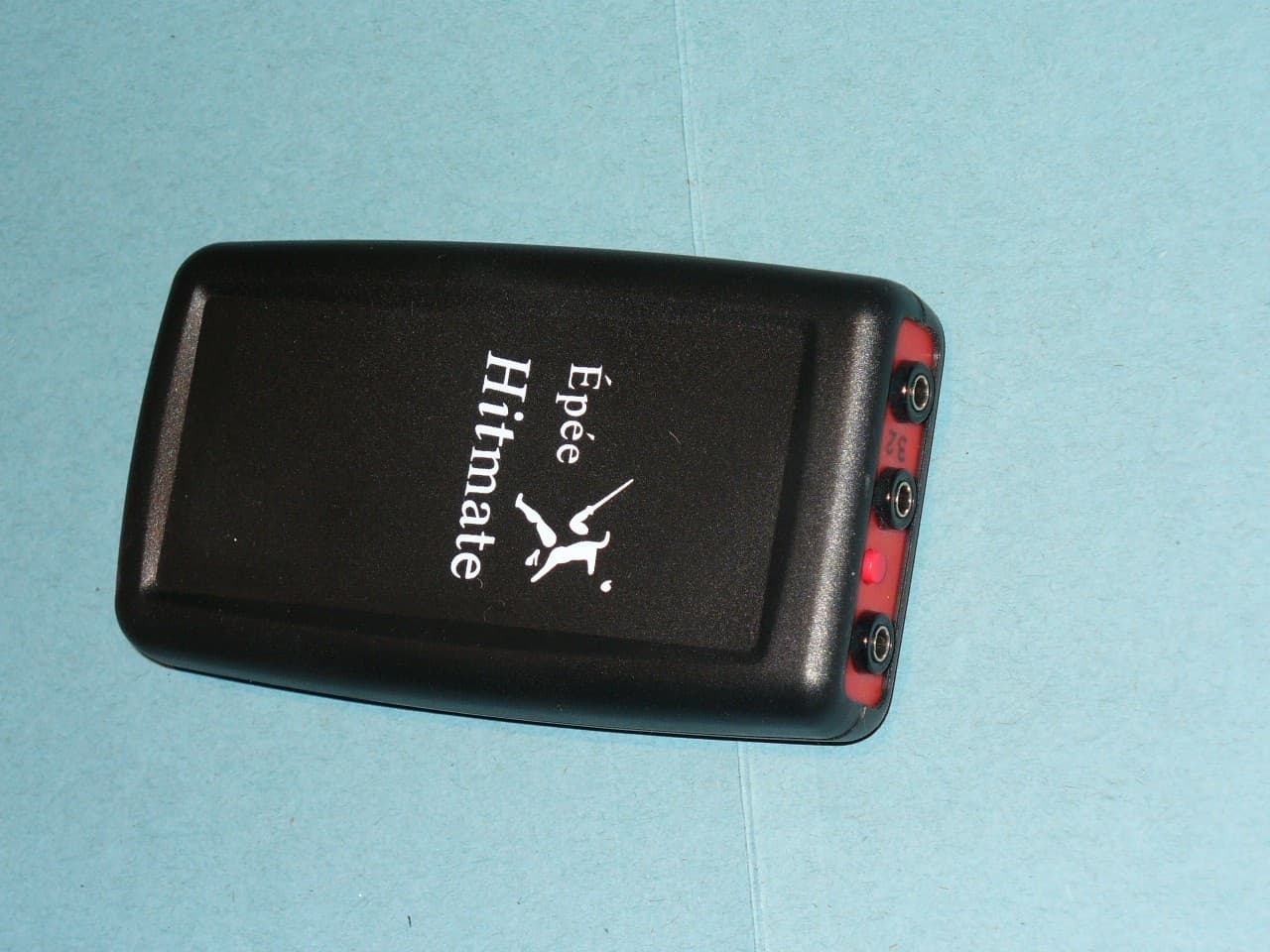
Click to zoom
Application Details
- Equipment Class
- DSC - Part 15 Security/Remote Control Transmitter
- Date of Grant
- Oct 12, 2011
- Application Purpose
- Original Equipment
- Date of Application
- Oct 12, 2011
- Equipment Note
- 2100 Series Scoring equipment for Fencing
- Frequency Range
- 433.92000000 - 433.92000000
- Company
- Hitmate Limited
- Country
- United Kingdom
Documents & Files
Document Text
Text extracted from the exhibit documents filed with the FCC. Open a document above to read the original.
Users Manual
Épée Hit mate User Guide Epée Hit mate The smallest, lightest scoring system for épée prac tice. It’s portable, convenient ...and fun to use! An Epee Hitmate set comprises three units: A pair o f Hitmate units (one Red, one Green) and a Hitmate Floor Console. A ll three should show the same number on the edge. Hitmate u ses a single radio frequency and the numbers allow units to reco gnise each other. This also allows many Hitmates to be used w ithin the same venue. 1 IntroductionEpee Hitmate works with a standard electric fencing weapon and a standard body-wire. It does not require spools, cables or an electric piste. Hitmate slips into the breeches po cket or is carried in an accessory holster.It’s important that the body-wire makes close conta ct with the fencer’s body, between the weapon and the Hitmate t ransmitter unit. Normally it’s sufficient to route the body-w ire up the sleeve (inside the plastron if worn) and across the back. Batteries The Console case is enclosed in a rubber boot. Re move the boot by first easing back one of the top corners, then t he second top corner, and finally pull the case out of the front of the boot.The Console and Hitmate units are powered by standard 9v batteries (type MN1604A or PP3).Open the battery compartment at the back. Clip in the battery and close the battery compartment. An alkaline battery can be expected to give about 100 hours of use.Switching onSwitch on Hitmate and the Console by pressing the r ed button on the top edge. Each unit should emit a single beep. If it does not, you need to check that the battery is correctly con nected and is not exhausted. The unit does not beep again if the but ton is pressed when the unit is already switched on.Switch-offTo maximise battery life, Hitmate switches itself o ff after 30 minutes of inactivity. Hitmate can also be switche d off by holding the weapon tip switch closed for more than 5 second s. The Console switches itself off after 30 minutes of continuous inactivity. It cannot be switched off manually.Battery ReplacementWhen the internal battery has reached the end of it s useful life, transmitter range will be reduced and the unit may switch off before the normal 30 minute interval. Always use a lkaline batteries for best results. Rechargeable 9v batter ies do not last so long. 2 OperationWhen a fencer scores a touch on the opponent, the é pée tip switch operates and Hitmate signals to the Floor Console. The Console beeps and flashes a red or green light, indicating the hit. Once a hit is scored, both Red and Green are locke d out for a period of about 2 seconds. If opponents make hits in close succession, only the first to hit is indicated by t he Console. Double hitsIf both opponents hit within one twenty-fifth of a second, the Console indicates both Red and Green.Non-scoring hitsWhen one player’s épée hits the opponent’s bell-gua rd, that player is locked out for a period of 5 ms, and no hit is i ndicated by the console. For the guard detect mechanism to work pr operly, the body wire must be worn inside the tunic sleeve by b oth players. The body provides an earth reference.Hits to a metal piste do not register on the consol e. Hits to a wooden floor do register on the console. 3 Pre-bout checkIt’s good practice before the start of a bout to pr ess the weapon tip onto your shoe to ensure the unit is registering hi ts. It’s also good to press the weapon tip to the opponent’s bell guar d and confirm no hit is registered. Unlike wired fencing, you can’t use your ungloved h and to press the tip and test for a score response. Hitmate det ects your hand the same as a guard, and does not register a hit. If you hold the tip pressed too long, Hitmate will switch itself of f. Guard hit detectionThe bell guard is earthed through the fencer’s body , and Hitmate detects contact with earth when it registers a non- scoring hit to the guard. Occasionally, a sweat-soaked tunic can be c onductive to earth. If Hitmate appears not to register hits aft er working well for a period of time, consider whether the opponent’s t unic has become affected by sweat.Operational checksIf intermittent operation is suspected, it’s useful to have some fail-proof tests available. With Hitmate and the C onsole switched on, the first test is to press the épée tip on to a ny insulated surface, such as your shoe, and confirm that a hit is regist ered. Next, try pressing the tip to an electrical ground, such as the metalwork of a radiator or water tap. A touch to a good earth such as this should never register on the console as a h it. These two tests are all that is needed to confirm t hat Hitmate is working correctly. The next two tests check the co upling between Hitmate and the fencer’s body. 4 Coupling checksPress the weapon tip with your hand or finger, maki ng contact with the bare skin. No hit should be registered. If th e Console does register a hit in this case, repeat it while touchi ng your own bell guard. If now there is no hit registered, then t he coupling between the body wire and your body is not good enough. Normally it is adequate to have the body-wire runni ng the length of the arm, inside the sleeve. For better coupling, e nsure the body wire is inside the plastron (if worn) then route the wire over th e shoulder and down the back, inside the tunic.Try a touch to the opponent’s hand (not glove). Th is should not register a hit. Then try a touch to the opponent’s guard. This also should not register a hit. If it does register, th e opponent’s body wire is not well coupled to the body, or there’s no connection to the ‘far’ pin of the opponent’s body wire.It’s only necessary to do these checks if you suspe ct Hitmate is not working the way you expect. Normally, you just pas s the body wire down your sleeve, plug in both ends and start fenci ng. QuestionsFencing without wires may feel unusual at first. If we can resolve any questions you have, please em ail us at [email protected] . We will do our best to …
Text truncated - open the document above for the full version.
Cover Letter(s)
Hitmate Training & practice equipment for the twenty-first century Directors: Ray Malcomber, Ian Bowden Hitmate Limited, 19 Riverside Drive, Richmond, Surrey TW10 7QA Telephone 020 8948 8147 Registered in England No. 4475373 VAT Registration No 973 1456 07 Request for Confidentiality Date: 29 July 2011 Subject: Confidentiality Request for FCC ID XCU2102 Pursuant to FCC 47 CRF 0.457(d) and 0.459 and IC RSP-100, Section 10, the applicant requests that a part of the subject FCC application be held confidential. Type of Confidentiality Requested Exhibit Short Term Permanent Block Diagrams Short Term External Photos Short Term Permanent* 1 Internal Photos Short Term Permanent Operation Description/Theory of Operation Short Term Permanent Parts List & Placement/BOM Short Term Permanent Tune-Up Procedure Short Term Permanent Schematics Short Term Test Setup Photos Short Term Permanent* User’s Manual Hitmate Limited has spent substantial effort in developing this product and it is one of the first of its kind in industry. Having the subject information easily available to "competition" would negate the advantage they have achieved by developing this product. Not protecting the details of the design will result in financial hardship. Permanent Confidentiality: The applicant requests the exhibits listed above as permanently confidential be permanently withheld from public review due to materials that contain trade secrets and proprietary information not customarily released to the public. Sincerely, for HITMATE LIMITED Ian Bowden Director
External Photos
External Photos
ID Label/Location Info
64mm Print in white direct onto case Indicated area is 64 x 45mm panel Battery compartment is on this side Centre Line BACK FCC ID: XCU2102
Internal Photos
Internal Photos
Test Report
Hursley EMC Services Ltd. Unit 16, Brickfield Lane Chandlers Ford Hampshire. UK. SO53 4DP EMC TEST REPORT No. 11R383 CFR Issue#1: 9 th September 2011 Tel. +44 (0) 23 8027 1111 Fax. +44 (0) 23 8027 1144 e mail. [email protected] www.hursley-emc.co.uk UKAS Accredited EU Notified Body FCC & VCCI Registered BSMI Lab ID: SL2-IN-E-3008 FCC Part 15 & Industry Canada Certification Report for the Hitmate Limited Epee Hitmate Transmitter and Hitmate Console Receiver (434 MHz) Project Engineer: R. P. St John James Approval Signatory Approved signatories: S. M. Connolly J. A. Jones The above named are authorised Hursley EMC Services engineers. EMC TEST REPORT 11R383 CFR FCC Part 15 Certification Report Issue#1: 9 th September 2011 Page 2 of 22 Contents 1.0 DECLARATION ................................................................................................................................................3 1.1 STATEMENT OF COMPLIANCE................................................................................................................................3 1.2 RELATED SUBMITTAL(S) .......................................................................................................................................3 1.3 EUT MANUFACTURER..........................................................................................................................................3 2.0 EUT DESCRIPTION .........................................................................................................................................4 2.1 IDENTITY...............................................................................................................................................................4 2.2 PRODUCT OPERATION...........................................................................................................................................4 2.3 SUPPORT EQUIPMENT............................................................................................................................................4 2.4 EXERCISER PROGRAM...........................................................................................................................................4 3.0 MEASUREMENT PROCEDURE AND INSTRUMENTATION .................................................................5 3.1 EMI SITE ADDRESS & TEST DATE........................................................................................................................5 3.2 GENERAL OPERATING CONDITIONS......................................................................................................................5 3.3 ENVIRONMENTAL AMBIENT..................................................................................................................................5 3.4 RADIATED EMISSIONS...........................................................................................................................................6 3.5 CONDUCTED EMISSIONS........................................................................................................................................6 4.0 TEST DATA .......................................................................................................................................................7 4.1 TRANSMITTER – RADIATED EMISSIONS.................................................................................................................7 4.2 RECEIVER – RADIATED EMISSIONS.......................................................................................................................9 4.3 MODULATION BANDWIDTH.................................................................................................................................10 4.4 TRANSMISSION TIME...........................................................................................................................................10 5.0 TEST PLOTS....................................................................................................................................................11 5.1 TRANSMITTER EMISSION PLOT, 30 TO 1000 MHZ...............................................................................................11 5.2 RECEIVER EMISSIONS PLOT, 30 TO 1000 MHZ....................................................................................................12 5.3 TRANSMITTER EMISSIONS (IDLE) PLOT, 30 TO 1000 MHZ..................................................................................13 5.4 TRANSMITTER EMISSIONS PLOTS, 1 TO 10 GHZ..................................................................................................14 5.5 TRANSMITTER EMISSION (IDLE) PLOT, 1 TO 10 GHZ...........................................................................................15 5.6 RECEIVER EMISSION PLOTS, 1 TO 10 GHZ...........................................................................................................16 5.7 99% BANDWIDTH PLOT.......................................................................................................................................17 5.8 BANDWIDTH PLOT...............................................................................................................................................18 5.9 TRANSMITTER ON TIME PLOT.............................................................................................................................19 5.10 TRANSMITTER DUTY CYCLE PLOT......................................................................................................................20 6.0 FCC LETTER..................................................................................................................................................21 7.0 INDUSTRY CANADA LETTER....................................................................................................................22 EMC TEST REPORT 11R383 CFR FCC Part 15 Certification Report Issue#1: 9 th September 2011 Page 3 of 22 1.0 DECLARATION…
Text truncated - open the document above for the full version.
Test Setup Photos
EMC TEST REPORT No. 11R383 Tel. +44 (0) 23 8027 1111 Fax. +44 (0) 23 8027 1144 e mail. [email protected] www.hursley-emc.co.uk Hursley EMC Services Ltd. Unit 16, Brickfield Lane Chandlers Ford Hampshire. UK. SO53 4DP 1871 UKAS Accredited EU Notified Body FCC & VCCI Registered BSMI Lab ID: SL2-IN-E-3008 Photo Log for the Hitmate Limited Epee Hitmate Transmitter and Hitmate Console Receiver (434 MHz) EMC TEST REPORT 11R383 FCC Part 15C Certification Report Page 2 of 5 1.0 PHOTO LOG Transmitter Receiver EMC TEST REPORT 11R383 FCC Part 15C Certification Report Page 3 of 5 Photo Log (continued) Open area test site measurements with Horn Antenna (axis 1) EMC TEST REPORT 11R383 FCC Part 15C Certification Report Page 4 of 5 Photo Log (continued) Open area test site measurements with Horn Antenna (axis 2) EMC TEST REPORT 11R383 FCC Part 15C Certification Report Page 5 of 5 Photo Log (continued) Open area test site measurements with Horn Antenna (axis 3)
Contact Information
Applicant
Ian Bowden(Technical Director)
Test Firm
Eurofins Hursley LtdAndrew Coombes
Technical Specifications
| # | Rule Parts | Frequency Range | Power Output |
|---|---|---|---|
| 1 | 15.231 | 433.92 MHz - 433.92 MHz | - |