FCCID.CO- FCC ID Database
HomeCompaniesEquipment ClassesSearch

© 2026 FCC ID Database. All rights reserved.

AboutContactData sourced from FCC public records
  1. Home/
  2. HBK Inc/
  3. XJQMSLINK0003

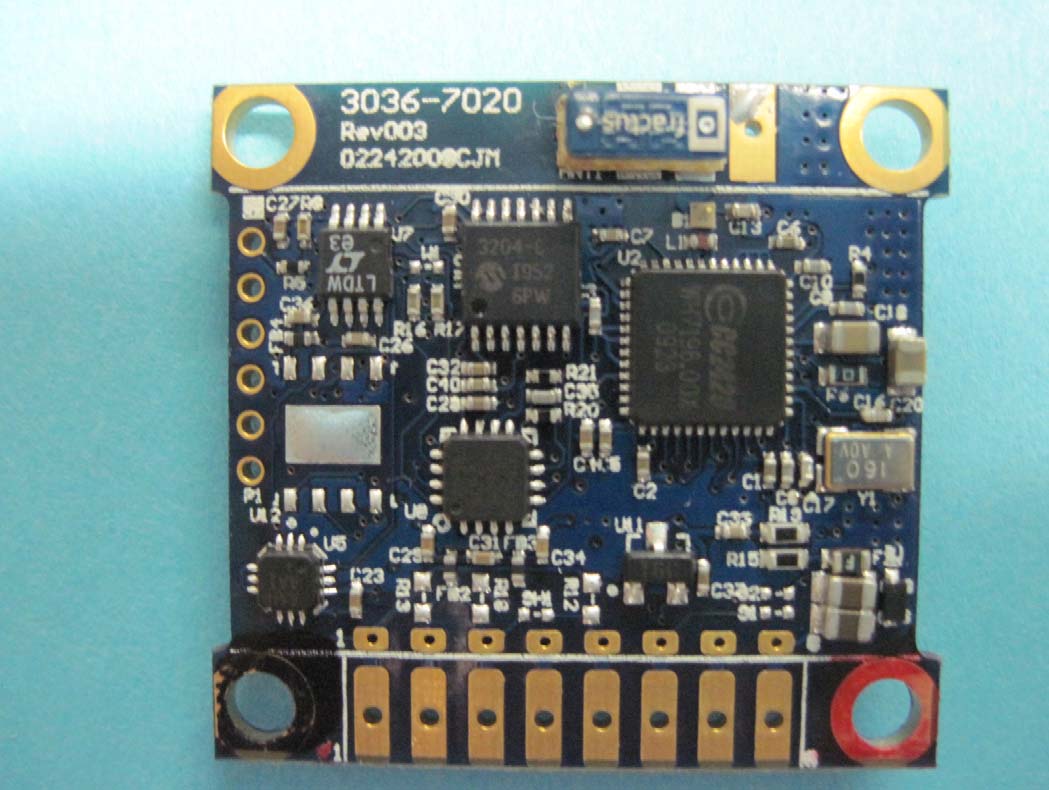
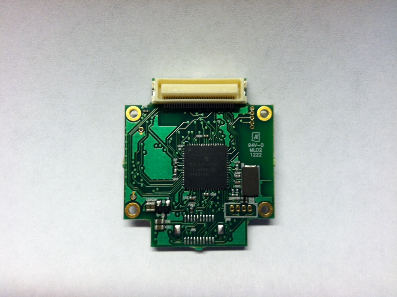
XJQMSLINK00032.4 GHz Radio Module

HBK Inc
2.4 GHz Radio Module - FCC ID XJQMSLINK0003 - HBK Inc
Click to zoom

Application Details

Equipment Class
DTS - Digital Transmission System
Date of Grant
Sep 03, 2012
Application Purpose
Original Equipment
Date of Application
Aug 29, 2012
Equipment Note
2.4 GHz Radio Module
Frequency Range
2405.00000000 - 2475.00000000
Company
HBK Inc
Country
United States

Documents & Files

Select a file to view

Users Manual

↗

Attestation Statements

↗

Cover Letter(s)

↗
↗
↗
↗

External Photos

↗
↗

ID Label/Location Info

↗

Internal Photos

↗

RF Exposure Info

↗

Test Report

↗

Test Setup Photos

↗

Document Text

Text extracted from the exhibit documents filed with the FCC. Open a document above to read the original.

Users Manual

SerialLink Manual Serial-Link Serial Packet Protocol (SPP) Draft version 1.20, for Internal MicroStrain use only Working Draft: 8/7/2012 Overview The Serial-Link Serial Packet Protocol (SPP) defines a standard for delivery of data and commands over the Serial-Link UART communications pipeline. To communicate, each device is capable of reading, responding to, and forwarding an SPP Packet. Any device may originate a message and receive a reply from any other device. A single packet may be delivered to multiple devices. If a device does not exist on the pipeline, or is incapable of responding to a particular packet, it replies with an error, but will propagate the packet to the next device, if it exists, so that the next device may respond to the packet. The protocol to send a packet is shown below. Hardware UART specifications 115,200 bps, no parity, 8 data bits, 1 stop bit Packet Description The basic structure of the SPP Packet looks like this: Start Of Packet (SOP): 0xAA Delivery Stop Flags: <1 byte> App Data Type: <1 byte> Node Address: <2 bytes> Application data Length: <1 byte> Application data: <0 to 100 bytes> CheckSum: <2 bytes> The size of the packet is always AppDataLength + 8 (except for a variant – see Packet Variants) and the checksum is always the last 2 bytes (even for variants). Start Of Packet (SOP) (1 byte: Pkt[0]): The start of packet is a single byte of the value 0xAA (or binary 10101010) Delivery Flags (1 byte: Pkt[1]) Delivery flag instructs the receiving device how to act upon reception of the packet. This is currently fixed at a hex value 01H which instructs the receiving device to forward the received packet over its UART. App Data Type (previously: Address Mode) (1 byte: Pkt[2]) The App Data Type defines the type of the application data. It allows the target MCU to determine what to do with the payload. If a target MCU does not recognize the App Data Type, it simply ignores it (or generates an error reply). Even if a target does not recognize the App Data Type, it should still pass the packet through to the next target (if any). All devices should utilize the Standard Command App Data Type (and the corresponding Command Packet Reply) for most I/O. Standard command app data has an App Data type value of 0. The Application Data in a standard command packet contains a 2 byte (16 bit, MSB:LSB) command followed by command data (if any). The standard command generally reflects available serial (non-packet) commands for a device. In other words, the application data of a standard command data type is simply a standard serial command wrapped in a packet header and checksum. If a Command Packet generates a reply, the reply should be in a Command Packet Reply App Data Type. Other standard App Data Types are: App Data Type Name Description 00 Command packet 2 byte command + command data 01 Cmd Packet reply 2 byte echoed cmd + cmd result 02 Error reply packet 2 bytes of error code Node Address (2 bytes: Pkt[3] Pkt[4]) In outbound packets the Node Address is the address of the wireless link node. The exception is the “broadcast” address which is defined as 0xFFFF (65535). Packets addressed to 0xFFFF are received and processed by all nodes. The node address allows the Serial-Link pipeline to become a “star” network at the base station to link board device. Each node on the star has an individual 16 bit address with valid address values being in the range of 1 to 65535. Practically speaking, a single star cannot have 65535 nodes at one time. The practical limit depends primarily on the duty cycle of the nodes, the limitations of the supporting host software, and the link quality or LQI (in the case of a wireless link). Application Data Length (1 byte: Pkt[5]) The maximum application data is restricted to 100 bytes. It may contain any binary data. Application Data (0 - 100 bytes: Pkt[6] -> Pkt[AppDataLen + 5]) In the SerialLink system, there are some commands carried in the application data that are common to all devices and so no prior knowledge of the type of device is needed, but there are many command and data application datas that are specific to a particular device. These commands are referenced in the documentation for the particular device. As a general convention, multi-byte values in the application data are recommended to be represented as big-endian values (MSB:LSB). Several standard app data types Checksum (2 bytes: Pkt[AppDataLen + 6], Pkt[AppDataLen + 7]) The checksum is a 16 bit big-endian integer (MSB:LSB) that is the byte-wise sum of all the bytes in the packet starting AFTER the SOP and ending with the last byte of the application data. The SOP is not part of the checksum. In packet variants (see Packet Variants) additional packet bytes between the application data and the checksum bytes are NOT included in the checksum. The length of the array that is checksummed is AppDataLength + 5. The total size of the packet including the checksum bytes is AppDataLength + 8. POWERING THE DEVICE AND CONNECTING TO THE UART The device is powered by providing a DC voltage between 3.3 volts and 10 volts on pin 4 of the input connector. The ground return is provided on Pin 14 of the input connector. The voltage input is internally regulated to provide a steady 3.0 Voltage source to the board. Pin 19 is the Transmit Line of the UART, this should be connected to the receive line of the interface microprocessor. Pin 18 is the RX Line of the UART, this should be connected to the transmit line of the interface microprocessor. The interface voltage levels should be 3.0 V +/ 0.3 V. ALLOWABLE ANTENNAE The device has been tested for FCC approval with the following antenna. This antenna must be used with this module. The external antenna connects to the module via a u.FL connector. HG2402RD-RSF Manufacturer: L-Com Electrical Specifications Frequency 2400-2500 MHz Gain 2.2 dBi Impedance 50 Ohm VSWR < 2.0 HOST PRODUCT LABELING: The host product must be labeled with the following: “Contai…

Text truncated - open the document above for the full version.

Cover Letter(s)

Page 1 of 1 American TCB 6731 Whittier Avenue, Suite C110 McLean, VA. 22101 To whom it may concern: The enclosed documents constitute a formal submittal and application for Equipment Authorization for a modular DTS transceiver pursuant to the following rules: Subpart C of Part 15 of FCC Rules (CFR 47), Intentional Radiators RSS-Gen Issue 3, December 2010, “General Requirements and Information for the Certification of Radiocommunication Equipment” RSS-210, Issue 8, December 2010, “Low-power Licence-exempt Radiocommunication Devices (All Frequency Bands): Category I Equipment” Elliott Laboratories, as duly authorized agent prepared this submittal. A copy of the letter of our appointment as agent is included with the application. If there are any questions or if further information is needed, please contact Elliott Laboratories for assistance. Sincerely, David W. Bare Chief Engineer

Cover Letter(s)

Full Modular Approval is being requested for this device. The following paragraphs detail the requirements for modules and explain how the module meets those requirements. Where requirements are not met a justification for a limited modular approval is presented. FCC §15.212 Requirements for Single Modular Transmitters (includes RSS GEN Section 3.2.2) (a) Single modular transmitters consist of a completely self-contained radiofrequency transmitter device that is typically incorporated into another product, host or device. Split modular transmitters consist of two components: a radio front end with antenna (or radio devices) and a transmitter control element (or specific hardware on which the software that controls the radio operation resides). All single or split modular transmitters are approved with an antenna. All of the following requirements apply, except as provided in paragraph (b) of this section. (1) Single modular transmitters must meet the following requirements to obtain a modular transmitter approval. (i) The radio elements of the modular transmitter must have their own shielding. The physical crystal and tuning capacitors may be located external to the shielded radio elements. All radio components including RF oscillator are shielded with a metal can attached to the PCB. (ii) The modular transmitter must have buffered modulation/data inputs (if such inputs are provided) to ensure that the module will comply with part 15 requirements under conditions of excessive data rates or over-modulation. All data inputs are buffered through a microprocessor, no direction external connections to the radio are provided. (iii) The modular transmitter must have its own power supply regulation. An internal voltage regulator is provided, this regulates the system voltage to the transmitter to 3.0 Volts DC fixed. (iv) The modular transmitter must comply with the antenna and transmission system requirements of §§15.203, 15.204(b) and 15.204(c). The antenna must either be permanently attached or employ a “unique” antenna coupler (at all connections between the module and the antenna, including the cable). The “professional installation” provision of §15.203 is not applicable to modules but can apply to limited modular approvals under paragraph (b) of this section. The external antenna connects to the module via a u.FL connector. This connector is a non-standard connector. The antenna is a 2.4GHz omnidirectional "rubber-duck" antenna with a gain of 2.2 dBi (L-com P/N: HG2402RD-RSF) (v) The modular transmitter must be tested in a stand-alone configuration, i.e., the module must not be inside another device during testing for compliance with part 15 requirements. Unless the transmitter module will be battery powered, it must comply with the AC line conducted requirements found in §15.207. AC or DC power lines and data input/output lines connected to the module must not contain ferrites, unless they will be marketed with the module (see §15.27(a)). The length of these lines shall be the length typical of actual use or, if that length is unknown, at least 10 centimeters to insure that there is no coupling between the case of the module and supporting equipment. Any accessories, peripherals, or support equipment connected to the module during testing shall be unmodified and commercially available (see §15.31(i)). Test data contained in this application is for the device tested in a stand-alone configuration. Radiated spurious emissions data and AC conducted emissions data demonstrating compliance with the requirements of Part 15 of the FCC rules for intentional radiators and RSS GEN/RSS 210 has been provided. (vi) The modular transmitter must be equipped with either a permanently affixed label or must be capable of electronically displaying its FCC identification number. (A) If using a permanently affixed label, the modular transmitter must be labeled with its own FCC identification number, and, if the FCC identification number is not visible when the module is installed inside another device, then the outside of the device into which the module is installed must also display a label referring to the enclosed module. This exterior label can use wording such as the following: “Contains Transmitter Module FCC ID: XYZMODEL1” or “Contains FCC ID: XYZMODEL1.” Any similar wording that expresses the same meaning may be used. The Grantee may either provide such a label, an example of which must be included in the application for equipment authorization, or, must provide adequate instructions along with the module which explain this requirement. In the latter case, a copy of these instructions must be included in the application for equipment authorization. (B) If the modular transmitter uses an electronic display of the FCC identification number, the information must be readily accessible and visible on the modular transmitter or on the device in which it is installed. If the module is installed inside another device, then the outside of the device into which the module is installed must display a label referring to the enclosed module. This exterior label can use wording such as the following: “Contains FCC certified transmitter module(s).” Any similar wording that expresses the same meaning may be used. The user manual must include instructions on how to access the electronic display. A copy of these instructions must be included in the application for equipment authorization. The module is appropriately labeled. The label is included on the shield of the transmitter. In the event this is located inside another enclosure a label is provided on the outside of the enclosure. (vii) The modular transmitter must comply with any specific rules or operating requirements that ordinarily apply to a complete transmitter and the manufacturer must provide adequate instructions along with the module to explain any such requirements. A copy of these instructions must be included in the application for equipment authoriz…

Text truncated - open the document above for the full version.

ID Label/Location Info

DETAIL A SCALE 10 : 1 A 1 1 2 2 AA BB SHEET 1 OF 1 DWG NO: 3036-0077 TITLE SIZE A REV 003 MicroStrain R 459 Hurricane Lane, Suite 102 Williston, VT 05495 802-862-6629 7/27/2011 DATE: CHECKED BY: DESIGNED BY: CAGE CODE OXYZ9 SCALE DRAWN BY: APPROVED BY: UNLESS OTHERWISE SPECIFIED ALL DIMENSIONS ARE IN INCHES. TOLERANCES:(UOS): .X = “ .02; .XX = “ .01; .XXX = “ .005 HOLE DIAMETERS: “ .002; ANGLES: “ 0.5ƒ SURFACE FINISH: 63 MICROINCHES MATERIAL: REV DESCRIPTIONDATEAPPROVED THIS DRAWING AND SPECIFICATIONS ARE THE PROPERTY OF MICROSTRAIN INC. AND SHALL NOT BE PRODUCED WITHOUT PERMISSION FROM MICROSTRAIN INC. TDA \\platypus\cad\Drawings\Projects\3036\3036-0077\REV 003\3036-0077.idw .185 .063 .036 .015" BRASS CDA 260, 1/2 HARD BRIGHT TIN PLATED .075 .080 .041 .020 .099 .020 .008 .090 37ƒ 53ƒ .121 3:1 RF SHIELD,1 PIECE,MXRS LINK TRNSMTR .008 TEXT AND LOGO DEPTH .038 .825 .035.041 .015 REF .593 .030 .074 .136 .199 .575 .333 .400 .091 .233 .034

RF Exposure Info

EMC Test Data Client: Contact: Standard: Test Specific Details General Test Configuration Yes Device complies with Power Density requirements at 20cm separation: Test Engineer: David Bare Calculation uses the free space transmission formula: S = (PG)/(4 πd 2 ) Where: S is power density (W/m 2 ), P is output power (W), G is antenna gain relative to isotropic, d is separation distance from the transmitting antenna (m). Summary of Results Maximum Permissible Exposure Objective: Evaluate the RF Exposure requirements per FCC 1.1310, 2.1091 and RSS-102. Date of Test: 7/10/2012 Matt Bissonnette FCC 15.247, RSS-210Class: - MicroStrain, Inc.Job Number: J87865 Model: Link Transceiver Module T-Log Number: T88104 Account Manager: Christine Krebill - 20cm separation: If not, required separation distance (in cm): Modifications Made During Testing No modifications were made to the EUT during testing Deviations From The Standard No deviations were made from the requirements of the standard. T88104 MicroStrain.xlsMPE CalculationPage 1 of 2 EMC Test Data Client: Contact: Standard: Matt Bissonnette FCC 15.247, RSS-210Class: - MicroStrain, Inc.Job Number: J87865 Model: Link Transceiver Module T-Log Number: T88104 Account Manager: Christine Krebill Use: General Antenna:Dipole Cable AntPower Freq.LossGainat AntEIRP MHzdBmmW*dBdBidBmmW 240511.514.00311.527.93 244011.614.50311.628.84 247511.413.70311.427.29 For the cases where S > the MPE Limit Fre q. MHz 2405 2440 2475 0.0061.0001.5cm 0.0051.0001.5cm S @ 20 cmMPE LimitDistance where 0.0061.0001.5cm 0.0061.000 0.0051.000 mW/cm^2mW/cm^2S <= MPE Limit Powe rat 20 cmat 20 cm mW/cm^2mW/cm^2 0.0061.000 EUTPower Densit y (S)MPE Limit T88104 MicroStrain.xlsMPE CalculationPage 2 of 2

Test Report

File: R88472 Rev 1 Page 1 EMC Test Report Application for Grant of Equipment Authorization Industry Canada RSS-Gen Issue 3 / RSS 210 Issue 8 FCC Part 15 Subpart C Model: Link Data Transceiver IC CERTIFICATION #: 8505A-MSLINK0003 FCC ID: XJQMSLINK003 APPLICANT: MicroStrain, Inc. 459 Hurricane Lane Suite 102 Williston, VT 05495 TEST SITE(S): NTS Silicon Valley 41039 Boyce Road. Fremont, CA. 94538-2435 IC SITE REGISTRATION #: 2845B-7 REPORT DATE: August 2, 2012 REISSUE DATE: August 28, 2012 FINAL TEST DATES: July 5 and 6, 2012 TOTAL NUMBER OF PAGES: 46 PROGRAM MGR / QUALITY ASSURANCE DELEGATE / TECHNICAL REVIEWER: FINAL REPORT PREPARER: ______________________________ ______________________________ David W. Bare David Guidotti Chief Engineer Senior Technical Writer NTS Silicon Valley is accredited by the A2LA, certificate number 0214.26, to perform the test(s) listed in this report, except where noted otherwise. This report and the information contained herein represent the results of testing test articles identified and selected by the client performed to specifications and/or procedures selected by the client. National Technical Systems (NTS) makes no representations, expressed or implied, that such testing is adequate (or inadequate) to demonstrate efficiency, performance, reliability, or any other characteristic of the articles being tested, or similar products. This report should not be relied upon as an endorsement or certification by NTS of the equipment tested, nor does it represent any statement whatsoever as to its merchantability or fitness of the test article, or similar products, for a particular purpose. This report shall not be reproduced except in full NTS Silicon Valley -- EMC Department Test Report Report Date: August 2, 2012 Reissue Date: August 28, 2012 File: R88472 Rev 1 Page 2 REVISION HISTORY Rev# Date Comments Modified By - 08-02-2012 First release 1 8-28-2012 Revised to clarify how the EUT was tested in 3 orthogonal orientations Dave Guidotti David Bare NTS Silicon Valley -- EMC Department Test Report Report Date: August 2, 2012 Reissue Date: August 28, 2012 File: R88472 Rev 1 Page 3 TABLE OF CONTENTS REVISION HISTORY ................................................................................................................................................ 2 TABLE OF CONTENTS ............................................................................................................................................ 3 SCOPE .......................................................................................................................................................................... 4 OBJECTIVE ................................................................................................................................................................ 5 STATEMENT OF COMPLIANCE ........................................................................................................................... 5 DEVIATIONS FROM THE STANDARDS .............................................................................................................. 5 TEST RESULTS SUMMARY ................................................................................................................................... 6 DIGITAL TRANSMISSION SYSTEMS (2400 – 2483.5MHZ) .............................................................................. 6 GENERAL REQUIREMENTS APPLICABLE TO ALL BANDS .......................................................................... 6 MEASUREMENT UNCERTAINTIES .................................................................................................................... 7 EQUIPMENT UNDER TEST (EUT) DETAILS ...................................................................................................... 8 GENERAL ................................................................................................................................................................ 8 ANTENNA SYSTEM .............................................................................................................................................. 8 ENCLOSURE ........................................................................................................................................................... 8 MODIFICATIONS ................................................................................................................................................... 8 SUPPORT EQUIPMENT ......................................................................................................................................... 9 EUT INTERFACE PORTS ...................................................................................................................................... 9 EUT OPERATION ................................................................................................................................................... 9 TEST SITE ................................................................................................................................................................. 10 GENERAL INFORMATION ................................................................................................................................. 10 CONDUCTED EMISSIONS CONSIDERATIONS .............................................................................................. 10 RADIATED EMISSIONS CONSIDERATIONS .................................................................................................. 10 MEASUREMENT INSTRUMENTATION ............................................................................................................ 11 RECEIVER SYSTEM ............................................................................................................................................ 11 INSTRUMENT CONTROL COMPUTER ............................................................................................................ 11 …

Text truncated - open the document above for the full version.

Test Setup Photos

Conducted Emissions Test Configuration Photographs Radiated Emissions Test Configuration Photographs Internal Antenna External Antenna

Contact Information

Applicant

Justin Bessette(Engineering Manager)
[email protected]8028626629Fax: 8028634093

Test Firm

Elliott Laboratories LLCDavid Bare
[email protected]408-245-7800Fax: 408-245-3499

Technical Specifications

#Rule PartsFrequency RangePower Output
115C2.40 GHz - 2.48 GHz15.00 mW
Modular Type
Single Modular Approval
Confidentiality
Long Term
Grant Notes
Modular Approval. Output Power listed is Conducted. The antenna(s) used for this transmitter must be installed to provide a separation distance of at least 20 cm from all persons and must not be co-located or operating in conjunction with any other antenna or transmitter except in accordance with FCC multi-transmitter product procedures. End users must be provided with antenna installation and transmitter operating conditions for satisfying RF exposure compliance.

Other Applications from HBK Inc

2.4 GHz OEM Wireless Module - FCC ID XJQMSLINK0002 - HBK Inc
XJQMSLINK0002

2.4 GHz OEM Wireless Module

Jul 20, 2010

Equipment Class

DTS - Digital Transmission System