XJW3GHC25cRIO GXXX 3G Mobile HSDPA Module
S.E.A. Datentechnik GmbH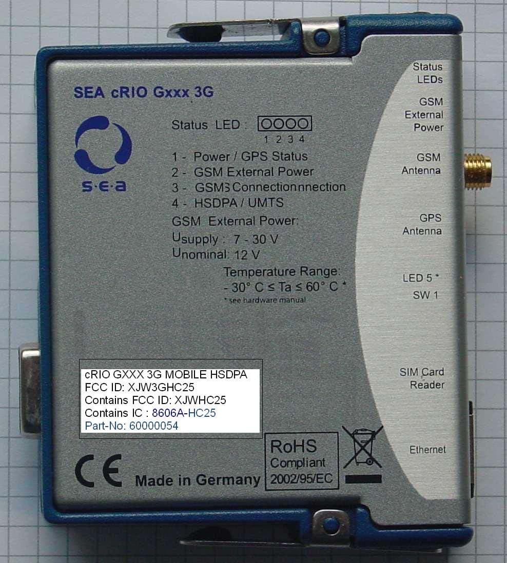
Click to zoom
Application Details
- Equipment Class
- JBP - Part 15 Class B Computing Device Peripheral
- Date of Grant
- Dec 13, 2009
- Application Purpose
- Original Equipment
- Date of Application
- Dec 13, 2009
- Equipment Note
- cRIO GXXX 3G Mobile HSDPA Module
- Company
- S.E.A. Datentechnik GmbH
- Country
- Germany
Documents & Files
Document Text
Text extracted from the exhibit documents filed with the FCC. Open a document above to read the original.
Users Manual
Hardware Manual for cRIO GXXX 3G Mobile Series Operation Instructions and Safety Guidelines cRIO GXXX 3G MOBILE HSPA cRIO GXXX 3G MOBILE HSDPA cRIO GXXX 3G MOBILE HSDPA SB *) cRIO GXXX 3G MOBILE HSDPA NTT *) cRIO GXXX 3G MOBILE CDMA SP **) cRIO GXXX 3G MOBILE CDMA VE **) *) Japanese Versions:SB=Softbank SIM Lock, NTT = NTT DoCoMo SIM Lock **) US Versions: SP=SPRINT, VE=Verizon SIM Lock Overview These operating instructions describe how to use the S.E.A. cRIO GXXX 3G Mobile module (later also referenced as module) with respect to the hardware. Please read this manual carefully. If there are any questions about oper ating the module or if any term or description in this manual is not un derstood, please contact S.E.A. Datentechnik GmbH before using the module, see S.E.A. Datentechnik GmbH Contact Information. Related Documentation: For information about National Instruments hardware please refer to the appropriate National Instruments manual. For information about installation, configuration, programming or operation of the cRIO GXXX 3G Mobile module, please refer to the cRIO GXXX 3G software manual. S.E.A. Datentechnik GmbH2Operation Instructions Safety Guidelines The user has to read this (hardware) manual as well as cRIO GXXX 3G software manual before operating the device. Operate the cRIO GXXX 3G Mobile modules only as described in these manuals. Hot or Cold Surface Denotes that the component may be hot or cold. Touching may result in bodily injury. Dangerous electrical voltage. Do not remove modules or disconnect I/O – wires or con nectors unless power has been switched completely off or the area is known to be non hazardous. Guarantee void if seal is broken! Important notes; these warnings can be specified by the addition Caution! Attention! Warning! or Danger! Hint or recommendation S.E.A. Datentechnik GmbH3Operation Instructions Safety Restrictions for Hazardous Locations The cRIO GXXX 3G Mobile modules are suitable for use in non hazardous locations only. Please note: Do not use for medical applications. Do not use for navigation and/or control of any vehicle (e.g. planes, cars, trains, boats etc.). Do not use in safety critical applications. Safety Guidelines for Hazardous Voltages Hazardous voltages must not be connected to the cRIO GXXX 3G Mobile module. A hazardous voltage is a voltage greater than 33 V peak AC or DC to earth ground. cRIO GXXX 3G Mobile Module Installation The cRIO GXXX 3G Mobile module must not be powered during in sertion into a chassis, insertion of a SIM card, or during connec tion with antennas and cables etc. Make sure working in an ESD safe environment. It is strictly recommended, to use the cRIO GXXX 3G Mobile mod ule only in combination with accessories provided by S.E.A. The usage with other accessories as antennas, cabling etc. not listed in the accessories list is not supported, and can lead to a loss of S.E.A. Datentechnik GmbH4Operation Instructions warranty. The cRIO GXXX 3G Mobile module is primarily foreseen for use within the CompactRIO chassis, but may also be used with: the NI R-Series Expansion chassis the S.E.A. RST Gateway USB adapter the S.E.A. cRIO-3G Mobile Mounting Kit None of those chassis are included with the module and have to be bought separately if needed. The operation of the cRIO GXXX 3G Mobile in other chassis as listed above is not allowed. The cRIO GXXX 3G Mobile module have a front side power supply con nector, a GSM antenna connector, a GPS antenna connector and a SIM card slot. The input voltage range of the module's power connector is 7 V to 30 V. Check the polarity of the wires before powering the system. Please note that the module's voltage range may possibly differ from the actual CompactRIO controller voltage range. After disconnecting the power supply or activating the sleep mode please wait at least 5 seconds before reconnecting the power supply again or awake from sleep mode. In other case the module can show unexpected behaviour. S.E.A. Datentechnik GmbH5Operation Instructions The SIM card slot has a slide-lock mechanism. Use slight force inserting the card. Refer to the scheme on the module cover for proper orientation of the SIM card. When using the module in rough environments the SIM card slot can be closed with a plastic plate. S.E.A. Datentechnik GmbH6Operation Instructions S.E.A. Datentechnik GmbH7Operation Instructions Fig. 1: Wiring of cRIO GXXX 3G Mobile Module Installation steps: Insert a SIM card into the SIM card slot (7) until the slide-lock mechanism is locked. It is recommended to use a small screw-driver or tweezers Insert the module in a slot of CompactRIO chassis. It is recommended to use slot 1 due to the length of the Ethernet Bridge cable, see step 3. Connect the module's Ethernet connector (8) with the CompactRIO controller network connector with the included Ethernet Bridge cable. Connect GPS antenna with the module's GPS antenna connector(4). Connect GSM/UMTS/CDMA antenna with the GSM antenna connector (3). Make sure An tenna is more than 1 m away from the sys tem Connect the power supply with the module's power connector (2) using the included power cable. Check polarity and supply voltage of power supply. The supplied power cable has a special label de scribing + and – wires. S.E.A. Datentechnik GmbH8Operation Instructions Fig. 2: Connector Side Finally refer to the instructions on antenna installation in chapters Transmitter Operation and GSM Antenna Installation and GPS An tenna Installation. For the actual list of the accessories please refer to www.sea-gmbh.com/crio. S.E.A. Datentechnik GmbH9Operation Instructions Fig. 3: Wiring the cRIO Gxxx 3G Mobile Module - Details Transmitter Operation and GSM Antenna Installation In this chapter the word transmitter is used interchangeably with the word cRIO GXXX 3G Mobile module, and means the RF-transmitter or RF- receiver part of the cRIO GXXX 3G Mobile module. The GSM antenna co…
Text truncated - open the document above for the full version.
Cover Letter(s)
Request for confidentiality CONFIDENTIALITY REQUEST FOR FCC ID: XJW3GHC25 To Whom It May Concern: In accordance with provisions of Section 0.457(d) of the Commission’s Rules and Section 552(b)(4) of the Freedom of Information Act, we request permanent confidentiality for transmitter’s exhibits, which contain Operation Description, Parts Lists, Block Diagram and Schematic Diagram. These exhibits contain proprietary, confidential and trade secrets material, which would not be routinely made available for public inspection. Also, in accordance with FCC Public DA 04-1705, we request short-term confidentiality until 2010/02/19 for exhibits, which contain External Photographs, Internal Photographs, Label Location Info, Test Setup Photos and the User Manual. These exhibits contain pre-market information, which could give our competitors unfair advantage should this information be released before this product is actually introduced into the common marketplace Do not hesitate to contact me if you have any additional questions. Company : 7 layers AG, Borsigstrasse 11, 40880 Ratingen Point of contact : Ms. Yao Jing, Project Manager Signed, 7 layers AG, (Ms. Yao Jing)
Internal Photos
Internal Photos FCC ID XJW3GHC25 Integrated Licensed Modular Approved Transmitter Module
Test Report
Final Report on cRIO GXXX 3G MOBILE HSDPA Module SW: 1.0.1 (SV15) HW: 1.04 MDE_SEA_0901_FCCb FCC part 15b Report Reference: November 19, 2009Date: Test Laboratory: 7 layer s AG Borsigstr. 11 DAT-P-192/99-01 40880 R atingen Germany Note: The following test results relate only to the devices specified in this document. This report shall not be reproduced in parts with out th e written approval of the t est l aboratory. 7 layers AG Au fsic hts rat svorsi tze nder h Registergerichth registered in: Bo rs igst ra sse 1 1 Chair man o f t he S up ervis or y B o ard : Düsseldorf, HRB 44096 408 80 Rat ing en, G erma ny Marku s B ecker US t-Id Nr h VAT No.: Phone: +49 (0) 2102 749 0 Vo rst andh Board: DE 203 159 652 Fa x: +4 9 (0) 21 02 7 49 350 Dr. Hermann Bu it ka mp TAX N o. 14 7/58 69/0 385 www.7La yers.com Wilfried Klassmann Reference: MDE_SEA_0901_FCCb FCC part 15b 2.3OUT Features Features for OUT: cRIO GXXX 3G MOBILE HSDPA Module Allowed ValuesDesignationDescriptionSupported Value(s) Features for scope: FCC_v2 Dantremovable antenna supplied and type tested with the radio equipment, designed as an example part of the equipment DCThe OUT is powered by or connected to DC Mains EDGE850EUT supports EDGE in the band 824 MHz - 849 MHz EDGE1900 EUT supports EDGE in the band 1850 MHz - 1910 MHz FDD2EUT supports UMTS FDD2 in the band 1850 MHz - 1910 MHz FDD5EUT supports UMTS FDD5 in the band 824 MHz - 849 MHz GSM850EUT supports GSM850 band 824MHz - 849MHz PantCpermanent fixed antenna connector, which may be built-in, designed as an indispensable part of the equipment PCS1900EUT supports PCS1900 band 1850MHz - 1910MHz 2.4Setups used for Testing For each setup a relation is given to determine if and which samples and auxiliary equipment is used. The left side list all OUT samples and the right side lists all auxiliary equipment for the given setup. Sample No.Sample DescriptionAE No.AE Description Setup No.List of OUT samplesList of auxiliary equipment B01 B01Sample: 3Results 3.1General Available at the test laboratory. The results of the inspection are described on the following pages, where 'Conformity' or 'Passed' means that the certification criteria were verified and that the tested device is conform to the applied standard. In cases where 'Declaration' is printed, the required documents are available in the manufacturers product documentation. In cases where 'not applicable' is printed, the test case requirements are not relevant to the specific equipment implementation. EUT complies with the Class B limits of §15.107 Documentati on of tested devices: Interpretation of the test results: Page 4 of 20 Reference: MDE_SEA_0901_FCCb FCC part 15b 3.2List of the Applicable Body (Body for Scope: FCC_v2) DesignationDescription Part 15, Subpart B - Unintentional RadiatorsFCC47CFRChIPART15bRADIO FREQUENCY DEVICES 3.3List of Test Specification Test Specification:FCC part 2 and 15 Date / Version2009/03/26 Version: 10-1-08 Edition Title:PART 2 - GENERAL RULES AND REGULATIONS PART 15 - RADIO FREQUENCY DEVICES Page 5 of 20 Reference: MDE_SEA_0901_FCCb FCC part 15b 3.4Summary Test Case Identifier / Name SetupDate of TestResultTest (condition)Ref. Lab 15b.2 Spurious Radiated Emissions §15.109 15b.2; Mode = transmit2009/09/10B01Lab 1Passed Page 6 of 20 Reference: MDE_SEA_0901_FCCb FCC part 15b 3.5Detailed Results 3.5.115b.2 Spurious Radiated Emissions §15.109 Test: 15b.2; Mode = transmit Result:Passed Setup No.:B01 Date of Test:2009/09/10 7:24 Body:FCC47CFRChIPART15bRADIO FREQUENCY DEVICES Test Specification:FCC part 2 and 15 Page 7 of 20 Reference: MDE_SEA_0901_FCCb FCC part 15b Detailed Results: EMI RADIATED TEST Diagram No.: 2.01 EUT: cRIO--Gxxx-3G (38130b01) Manufacturer: SEA Datentechnik GmbH Operating Condition: GPRS traffic Test Site: 7 layers, Ratingen Operator: MAC Test Specification: FCC 15 B Comment: Horizontal + vertical antenna polarisation Start of Test: 10.09.2009 / 10:51:56 0 10 20 30 40 50 60 70 80 Level [dBμV/m] 30M50M70M100M200M300M500M 700M 1G Frequency [Hz] x x x x x x x x x x x x x MES SEA_0901_009_fin QP MES SEA_0901_009_pre PK LIM FCC part 15 b Field Strength QP Limit MEASUREMENT RESULT: "SEA_0901_009_fin QP" Frequency Level Transd Limit Margin Height Azimuth Polarisation MHz dBμV/m dB dBμV/m dB cm deg 43.680000 9.40 13.0 40.0 30.6 125.0 112.00 VERTICAL 44.220000 8.80 12.7 40.0 31.2 101.0 124.00 HORIZONTAL 83.460000 27.10 10.0 40.0 12.9 124.0 157.00 VERTICAL 85.260000 20.80 10.1 40.0 19.2 111.0 191.00 VERTICAL 126.540000 17.90 10.7 43.0 25.1 106.0 157.00 VERTICAL 127.440000 19.10 10.6 43.0 23.9 100.0 193.00 VERTICAL 128.340000 15.70 10.6 43.0 27.3 125.0 247.00 VERTICAL 135.300000 16.60 10.2 43.0 26.4 105.0 157.00 VERTICAL 136.260000 15.70 10.2 43.0 27.3 100.0 157.00 VERTICAL 137.160000 15.90 10.1 43.0 27.1 105.0 157.00 VERTICAL 137.940000 18.70 10.0 43.0 24.3 100.0 157.00 VERTICAL 138.900000 16.20 10.0 43.0 27.8 100.0 165.00 VERTICAL Page 8 of 20 Reference: MDE_SEA_0901_FCCb FCC part 15b EMI RADIATED TEST Diagram No.: 2.01b EUT: cRIO--Gxxx-3G (38130b01) Manufacturer: SEA Datentechnik GmbH Operating Condition: GPRS traffic Test Site: 7 layers, Ratingen Operator: MAC Test Specification: FCC 15 B Comment: Horizontal + vertical antenna polarisation Start of Test: 10.09.2009 / 11:56:39 0 10 20 30 40 50 60 70 80 Level [dBμV/m] 300M400M500M600M700M800M1G Frequency [Hz] x x x x x x x x x x MES SEA_0901_010_fin QP MES SEA_0901_010_pre PK LIM FCC part 15 b Field Strength QP Limit MEASUREMENT RESULT: "SEA_0901_010_fin QP" Frequency Level Transd Limit Margin Height Azimuth Polarisation MHz dBμV/m dB dBμV/m dB cm deg 349.980000 38.10 15.5 47.0 8.9 106.0 112.00 HORIZONTAL 396.420000 36.30 16.8 47.0 10.7 102.0 149.00 HORIZONTAL 400.020000 41.10 16.9 47.0 5.9 111.0 112.00 HORIZONTAL 450.000000 38.10 18.4 47.0 8.9 100.0 158.00 HORIZONTAL 499.980000 43.00 19.6 47.0 4.0 155.0 192.00 HORIZONTAL 550.020000 38.00 20.6 47.0 9.0 105.0 158.00 VERTICAL 660.540000 37.60 22.8 47.0 9.4 100.0 0.00 HORIZONTAL 675.840000 39.…
Text truncated - open the document above for the full version.
Test Setup Photos
Reference: MDE_SEA_0901_Photo 1.2Additional Information for Test Plan setup for the test radiated emissions Seite 4 von 5
Contact Information
Applicant
Wolfram Koerver(Dipl. Ing.)
Test Firm
7layers AGRobert Machulec
Technical Specifications
| # | Rule Parts | Frequency Range | Power Output |
|---|---|---|---|
| 1 | 15B | - | - |
Other Applications from S.E.A. Datentechnik GmbH
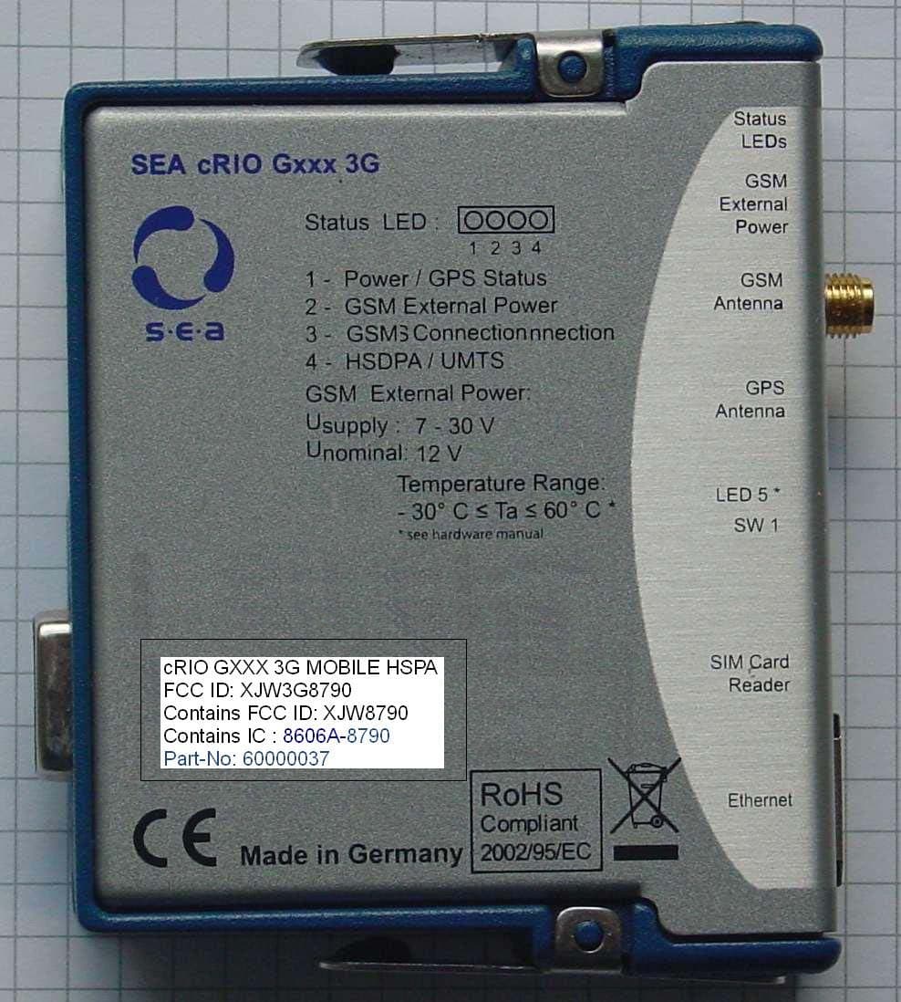
XJW3G8790
Jan 18, 2010cRIO GXXX 3G Mobile HSPA
Equipment Class
JBP - Part 15 Class B Computing Device Peripheral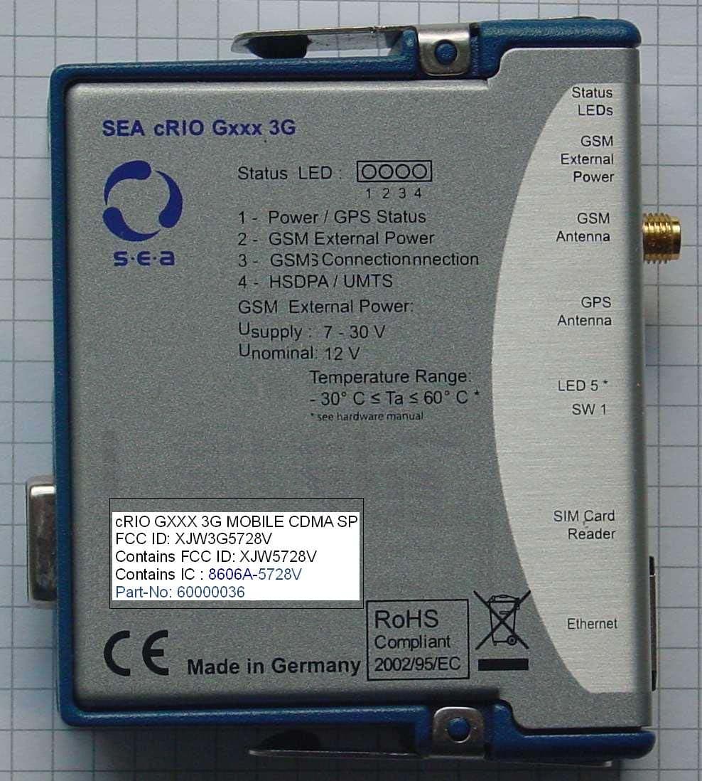
XJW3G5728V
Jan 18, 2010cRIO GXXX CDMA MOBILE
Equipment Class
JBP - Part 15 Class B Computing Device Peripheral